The cost of getting a piece of hardware into space is now cheaper than ever, thanks in no small part to the rapid progress that’s been made by commercial launch providers such as SpaceX. In the near future, as more low-cost providers come online, it should get even cheaper. Within a few years, we could be seeing per kilogram costs to low Earth orbit that are 1/10th what they were on the Space Shuttle. To be sure, this is a very exciting time to be in the business of designing and building spacecraft.
But no matter how cheap launches to orbit get, it’ll never be cheaper than simply emailing some source code up to the International Space Station (ISS). With that in mind, there are several programs which offer students the closest thing to booking passage on a Falcon 9: the chance to develop software that can be run aboard the Station. At the 2018 World Maker Faire in New York we got a chance to get up close and personal with functional replicas of the hardware that’s already on orbit, known in space parlance as “ground units”.
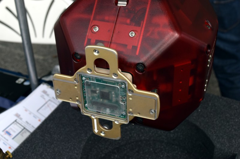
On display was a replica of one of the SPHERES free-flying satellites that have been on the ISS since 2006. They are roughly the size of a soccer ball and utilize CO2 thrusters and ultrasonic sensors to move around inside of the Station. Designed by MIT as a way to study spaceflight techniques such as docking and navigation without the expense and risk of using a full scale vehicle, the SPHERES satellites are perhaps the only operational spacecraft to have never been exposed to space itself.
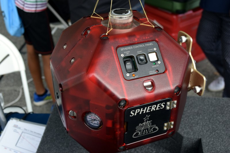
MIT now runs the annual “Zero Robotics” competition, which tasks middle and high school students with solving a specific challenge using the SPHERES satellites. Competitors run their programs on simulators until the finals, which are conducted using the real hardware on the ISS and live-streamed to schools.
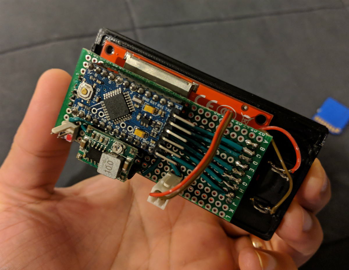
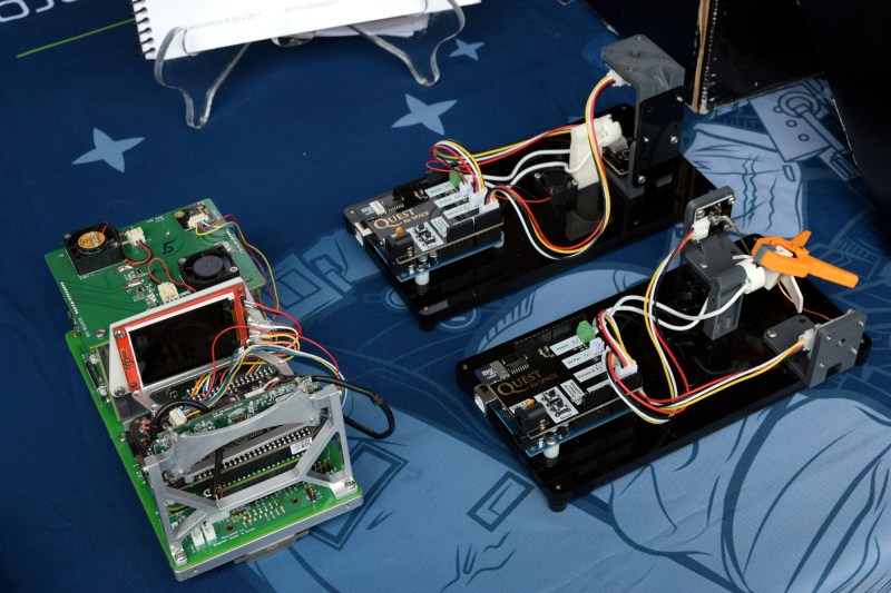
We also saw hardware from “Quest for Space”, which is a company offering curricula for elementary through high school students which include not only the ground units, but training and technical support when and if the school decides to send the code to the matching hardware on the Station. For an additional fee, they will even work with the school to design, launch, and recover a custom hardware experiment.
Their standard hardware is based on off-the-shelf platforms such as Arduino and LEGO Mindstorms EV3, which makes for an easy transition for school’s existing STEM programs. The current hardware in orbit is setup for experiments dealing with heat absorption, humidity, and convection, but “Quest for Space” notes they change out the hardware every two years to provide different experiment opportunities.


Projects such as these, along with previous efforts such as the ArduSat, offer a unique way for the masses to connect with space in ways which would have been unthinkable before the turn of the 21st century. It’s still up for debate if anyone reading Hackaday in 2018 will personally get a chance to slip Earth’s surly bonds, but at least you can rest easy knowing your software bugs can hitch a ride off the planet.