Posts with «adafruit» label

Roll up, roll up for the magical mystery Arduino tour

If this news isn't as obvious as John Obvious: Professor of Obvious studies at Cambridge University: we love Arduino 'round these parts. Phil and Limor of Adafruit Industries took a tour of the Italian foundry's Turin factory and took a gallery of pics (and video!) on the way. It's a great insight into how the building process works for the modding tool, and you can head on down to our source link to check out the gallery in full -- we've also included a direct link to the video as the guys walk down the production line in our more coverage link. We're so good to you, you know.

Roll up, roll up for the magical mystery Arduino tour originally appeared on Engadget on Fri, 13 Jan 2012 08:44:00 EST. Please see our terms for use of feeds.

Permalink | Email this | Comments
Engadget 13 Jan 13:44

Add lasers to a tennis ball, drive your dog crazy (video)

It's a "programmable disco ball," a "cat toy for humans," and a "personal laser light show," all rolled into one. That's how one Matt Leone describes his latest creation, aptly known as the Laser Ball. To realize his dream, Leone drilled a set of holes into a garden variety tennis ball, and inserted about 14 laser diodes, each with an attached strip of diffraction grating. Said diodes were then synced up with an Arduino-equipped Teensy microcontroller nestled within the ball, alongside a rechargeable battery. As a cherry on top of this DIY sundae, Leone then incorporated an infrared remote package from Adafruit, allowing him to remotely jump start his next house party. The result is a cyborg-like ball that makes any LED cube look... square. Check it out for yourself, in the video after the break.

Continue reading Add lasers to a tennis ball, drive your dog crazy (video)

Add lasers to a tennis ball, drive your dog crazy (video) originally appeared on Engadget on Mon, 14 Nov 2011 14:34:00 EST. Please see our terms for use of feeds.

Permalink | Email this | Comments

(F)Light Suit Major Components

The main components of the (F)Light suit:
(Updated 8/15/11)
Component(s)SourceStatus
LED stripsDealExtreme 22 strips with connectors, need sealing and velcro backing.
8-channel MOSFET Output BoardsDorkbotPDX board orderThree built and tested, work perfectly
Arm accelerometers Modern Device Left one on main board, right attached with 3-wire lead across shoulders
Black flight suit Amazon Needs velcro for LED strips
Arduino-compatible main board: Minimalduino 105 DorkbotPDX board order
Arduino interface board: Adafruit protoshield Adafruit Industries Done, ready for mounting and cable threading. Ports for MOSFET output boards, right accelerometer, remote control, audio sensor
Remote control homemade, various parts Needs laser-cut acrylic surround, rot 2 flaky
Batteries eBay 12V, 4800mAh Li-ion battery packs with barrel connectors, powering third MOSFET board.
Audio input: ZX-Sound board RobotShop.com Test, add light, change connector, paint, velcro back
Missing anything?

Hacking An Industrial CNC Lathe, Part I: Intro

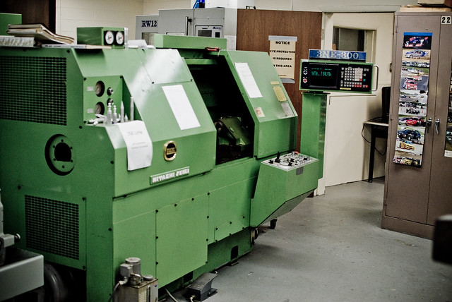
Hitachi-Seiki 3NE-300 Lathe, circa 1980

I’m currently taking some mechanical engineering classes at County College of Morris (CCM) in Randolph, NJ. Among the equipment in the machine shop is this mean, green Hitachi-Seiki CNC Lathe, a neat piece of industrial equipment from the late 70′s/early 80′s.

Currently, there are two ways to program the machine. You can program it manually, by entering in codes on the keypad:

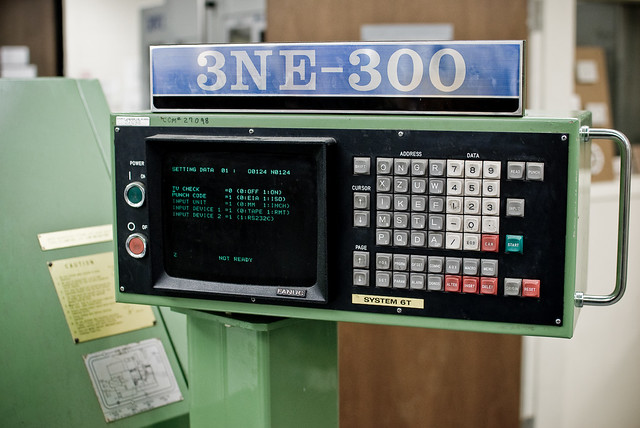
3NE-300 control panel

-OR- you can get your Jacquard on and write a program on punched tape:

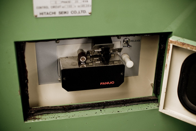
FANUC punched tape reader

Naturally, for ease of use, the punched tape reader is on the back of the machine. *sigh*

Fortunately, there is a third way to get program code into the controller. This is via an RS-232C port:

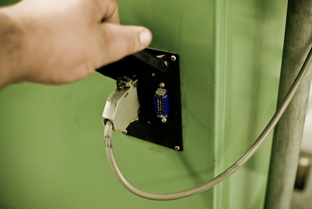
Serial port: a DB-25 RS-232-C port and an MR-20 "HONDA" connector

The obvious question is: why not just hook the serial port up to a computer? Well, due to the logistics of the shop, it’s not feasible to have a computer in the immediate vicinity of the machine. In order to hook it up to the nearest computer, the required cable would be at least 25 feet long. In practice, this translates to a 600-baud signaling rate, as there is a lot of EM interference in the shop, due to motors, fluorescent lights, etc. It’s much easier to simply have a small “black box” that can load the program from modern media like an SD card.

My plan is to build a circuit based around an Arduino, which will read an NC file (ASCII text) from an SD card and send it to the machine over the serial port. I plan to use the following hardware:

  • Arduino Mega – the brains of the operation. To be honest, I probably won’t need the extra pins of the Mega, but with the full SD library, the serial library and the extensive menu system I plan to write, I need the extra program memory.
  • LCD with Adafruit i2c/SPI backpack – for the display (file menu, load progress, etc.)
  • Adafruit Logger Shield – for reading from and writing to the SD card.
  • CuteDigi RS232 Shield – not entirely sure about this one yet. I may just get an Adafruit protoshield and wire up a DB-25 port to it.
  • Hammond 1550D enclosure – with milled openings for the SD card, LCD and buttons.

The controller for the lathe is a FANUC 6T-B. While rather primitive by today’s standards, in it’s day it was a top of the line industrial controller, and FANUC is still the standard. It’s pretty much indestructible too, which is a bonus, because it means I won’t end up scrambling the brains on a $20,000 piece of equipment.

More to come as I work on this project over winter break. I’m hoping to get the electronics soon and start work on the menu and input systems. By the time I get back to school in January, it’ll (hopefully) be ready to interface with the FANUC controller.