Nowadays visual indication is a must feature for any electronic device, which will make user interaction much easier. There are multiple ways to implement the visual indication, from simple light indications to LCDs or even holograms. Today we will be talking about such a device, which has been used in the industry for decades – the Seven-Segment Display.
If I ever take the plunge on an electric bike, I hope it’s a slick VanMoof. The company has unveiled two new models that are, unfortunately, slightly more expensive than their predecessors, but pack in a bunch of upgrades alongside impressive anti-theft technology. The S5 and A5 will each cost $2,998, but VanMoof hasn’t shared a release date just yet.
The new S5 is for longer rides. VanMoof reworked the straight frame to increase the height of the riding position and changed to larger 27.5-inch wheels for a smoother experience. Meanwhile, the A5 is more for shorter trips. It has an angled frame with a lower step-in and 24-inch wheels. There's support for both rear and front carriers as well. Both bikes weigh over 44 pounds.
The new models have an updated 250W motor, slightly different battery layouts (the S5 will cover up to 150 km (93 miles)), while the A5 has a range of up to 140 km (87 miles) and, gasp, a built-in phone charger.
Now, living in a big city, the biggest impasse for me is the fear of getting my new expensive e-bike stolen. Both the S5 and A5 include a Gen 5 kick lock you can arm with a tap of your foot. It'll unlock automatically when you return. VanMoof is working on certification for Apple’s Find My network and will continue to employ its Bike Hunters. If that team can't find and recover your premium e-bike within two weeks of it being lost or stolen, it'll send you a replacement. The service still requires the company’s Peace of Mind insurance, however.
After nearly a year of early access, Epic Games has officially released UE5 to developers. The new Unreal Engine's most obvious upgrades affect the basics of 3D rendering. The Nanite geometry system lets producers use objects with millions of polygons while scaling easily and maintaining playable frame rates. Lumen, meanwhile, provides dynamic global lighting that adapts to, pretty much, everything. You've seen early results in Epic's The Matrix Awakens tech demo — UE5 can render extremely detailed scenes with more natural lighting than you’ve seen in the past.
Crystal Dynamics is returning to the series that put it on the map.
And on that note, we’re getting a new Tomb Raider title. While the latest trilogy was generally well received, it didn’t quite set the world alight. Maybe more polygons will improve things. Developer Crystal Dynamics said the move to UE5 would help the studio take its “storytelling to the next level.” The next Tomb Raider joins a handful of games already announced for UE5, including the next Witcher game and Black Myth: Wukong.
LeVar Burton, Gates McFadden and Michael Dorn join the cast.
The main cast of Star Trek: The Next Generation will appear on the third and final season of Picard. LeVar Burton, Gates McFadden and Michael Dorn will join Jonathan Frakes, Marina Sirtis and Brent Spiner, who have already featured in the series. Executive Producer Terry Matalas teased on Twitter that the series will go out on a “final, high-stakes, starship-bound adventure.”
They'll build vehicles in the compact crossover and other segments.
GM and Honda will co-develop a series of affordable EVs using a global architecture and GM's Ultium battery technology, the companies announced. They promised to build vehicles in multiple product segments, including the compact crossover category, calling it a "new chapter" in their partnership. The companies plan to discuss EV battery collaboration in an effort to drive down costs and improve performance and sustainability.
The word "affordable" comes up a lot in the press release, as both companies emphasized the idea of building cheaper EVs than are currently available. "Honda and GM will build on our successful technology collaboration to help achieve a dramatic expansion in the sales of electric vehicles," said Honda President and CEO Toshihiro Mibe.
Nikon’s Z9 offers a rare combination of speed, resolution and video capability. It’s the first mirrorless camera without a mechanical shutter, but the sensor is fast enough to minimize any rolling shutter issues. It has Nikon’s best autofocus system by far and delivers outstanding image quality. Video is top-notch as well, with 8K 30p on tap and 8K 60p RAW coming later this year via firmware update.
The main drawbacks are the lack of an articulating display and the $5,500 price — for the body alone. It’s still an impressive Nikon camera – the company has finally nailed video. I’d suggest checking out our detailed YouTube review and sample shots on the main site.
Collaboration is a huge part of Google Docs, letting multiple users chip in edits, comments and more. Now, you can include not just text in your comments but emoji reactions, much as you can in messages or on social media. "The new emoji reactions feature provides a less formal alternative to comments to express your opinions about document content," Google said in a blog post announcing the feature.
Google
The new option appears when you highlight text in a document while in "editing" mode. From there, you'll see a new "add reaction" icon smiley face icon that lets you place emojis in the editing comments section. Google notes that emojis used will be shared with Google chat, "so any preferences set in one app will be reflected in the other." Both apps can also be used to update emoji preferences via the picker.
Google recently feted the 15th anniversary of Docs (along with Sheets). It has gradually boosted the feature set over that time, with the last update allowing you to draft emails in Docs and then send them using Gmail.
Emoji reactions on a Google Doc could be an easy way to add feedback, but then again they may not fly in some business environments. Either way, the feature can't be disabled by the user and "there is no Admin control for the feature," according to Google. The feature started officially rolling out yesterday, but it may take some time to appear depending on your domain type and region.
Anker, a company most known for its charging products, is getting into the 3D-printing business. The company has just announced AnkerMake, its new 3D printing brand, and its first model called AnkerMake M5. Anker claims that the M5 solves the most critical issues that have prevented 3D printers from going mainstream, including their typically slow print speeds.
The AnkerMake M5 has a basic print speed of 250 mm/s that's meant to be used if you're working on more detailed projects that need a smooth finish. However, the printer also has a much speedier mode that gives it the power to print up to 2,500 mm/s². The end result is rougher and less detailed, and the mode is mostly suitable for prototypes and perhaps random toys, but Anker says it enables the M5 to reduce average print times by up to 70 percent compared to other printers.
In addition to being speedy, the M5 was designed to be easy to set up: It will apparently only take 15 minutes to get it ready to start printing. To address another pain point — the need for constant supervision — Anker gave the M5 the capability to monitor print jobs with a built-in AI-powered camera. If it detects issues like nozzle plugging, it can send an alert to your phone. You can also view live feeds of your print jobs through the Anker mobile app wherever you are.
Whether the M5 can deliver on all those promises remains to be seen. At the moment, it's a Kickstarter project, which means it could take a while for Anker to start shipping the product, and that's if the campaign reaches its goal. If you want to back the project and don't mind waiting, you can get the the AnkerMake M5 for its super early bird price of $429. After that, you'll have to pledge at least $499 to secure a unit.
If you were trying to watch Drake, Taylor Swift, Lil Nas X, The Weeknd, Eminem, Ariana Grande, Harry Styles, Kanye West, Michael Jackson and other artists on YouTube this morning, you may not have seen what you expected. Music video network Vevo was reportedly attacked by someone with the Twitter handle @lospelaosbro, who uploaded some extremely strange clips, The Verge reported. Those included video of a rapper called Lil Tjay and a man called Paco Sanz who was sent to jail for scamming donations after lying about having cancer.
Vevo acknowledged the incident to The Verge, saying that "some videos were directly uploaded to a small number of Vevo artist channels earlier today by an unauthorized source." It added that no pre-existing content was accessible to the attacker and said that it would be "conducting a review of our security systems."
Vevo is owned primarily by music labels Sony Music Entertainment, Universal Music Group and Warner Music Group. The company says it controls "the largest network of music channels on YouTube," and essentially acts like a contractor, allowing distributors to merge Vevo channels with existing channels as "Official Artist Channels." Google supplies ads for Vevo videos and also owns a small stake in the service.
According to a Vevo FAQ, artists don't post their videos directly, but send them to "content providers" for uploading. Content providers include major labels like Universal Music Group and Sony Music, along with independent distributors. The hacked artist channels belong to multiple labels and Vevo said that they have now been secured and the incident is resolved.
The price for an Amazon Music Unlimited plan is going up from $8 to $9 for Prime members, Amazon has confirmed. It's also raising the price for a "Single Device" subscription from $4 to $5, as spotted byConsumer Reports reporter Nicholas De Leon. Non-Prime members will continue to pay $10 per month and the Family Plan will still cost $15 per month for Prime members only.
The news means that Prime subscribers are barely getting any kind of deal on Amazon Music Unlimited, whereas Prime Video is still included for free in the plan. The price is still a bit cheaper for Prime members than you'd pay for Apple Music ($10 per month) or Spotify ($10 per month). Amazon also offers Music Prime for free to Prime members, but you're limited to 2 million songs and can only play on one device at a time.
Amazon Music Unlimited is obviously best if you're a Prime subscriber and have an Echo or other Alexa device, though it works on tablets, smartphones, TVs, Amazon Fire devices, PCs and so on. However, the user interface is generally considered subpar compared to Apple Music or Spotify, lacking things like biographies in artist profiles. Some of the benefits include downloads for offline listening and HD, Dolby Atmos and Sony 360RA streaming at no extra cost.
Uber customers in San Francisco might soon find a traditional taxi waiting for them when they use the app to summon a ride. According to San Francisco Chronicle, the ride-hailing giant has inked a deal with Yellow Cab SF and Flywheel, the company that operates an Uber-like app used by taxi drivers across companies in the city. The agreement will give 1,075 taxi drivers in the area access to Uber customers in the coming months. Uber recently struck a similar deal in NYC, allowing people in the city to hail any of its 14,000 taxi drivers through the app.
The companies were able to finalize the deal, because the San Francisco Municipal Transportation Agency board has just voted in favor of allowing taxis to accept flat upfront rates for rides hailed through a third-party app. Customers can expect to pay UberX rates, which are calculated based on trip time and distance on top of a base fare, for taxi rides. The year-long pilot for the deal will begin on August 5th.
Uber's rates are typically lower than metered fares, though they could be higher during surge times. Kate Toran, SFMTA's director of taxis, said during the board meeting that Uber and Lyft fares are about 80 to 85 percent of metered rates. While drivers could earn less than usual for Uber rides, their participation is completely optional. They can accept Uber rides whenever they want, and there are no consequences for rejecting them.
Flywheel and Yellow believe the deal would benefit drivers, who could accept Uber rides to fill in gaps for dead hours. "[H]aving some revenue come in versus no revenue is a much better situation in the end, even if it is lower than the taxi rate," Yellow Cab CEO Chris Sweis said. Still, not all SF cab drivers are thrilled about the development. Mark Gruberg, a board member of the San Francisco Taxi Alliance, expressed concerns about regular taxi customers being ignored during Uber surge times. Another driver told ABC7News that earning less money from Uber rides would mean he'll have a harder time paying off the debts he took to pay for his medallion, which cost $250,000.
If Uber gets its way, though, there'll be no taxi left that isn't part of its network. Uber exec Andrew Macdonald recently said during an investor presentation (PDF) that that the company aims to put every taxi on Uber by 2025. Doing so wouldn't only increase its driver supply, it could also unlock new markets where people don't have their own cars to use for the service.
Facebook is taking another step to encourage users to create original content for its TikTok clone. The company introduced a new “sharing to Reels” feature to allow users of third-party apps to post directly to Facebook Reels.
The update allows outside developers to add a “Reels button” to their app so users can post clips directly to Reels while taking advantage of Reels’ editing tools, Facebook wrote in a blog post. Initial developers to use the feature include Smule, which makes a popular karaoke app and video editing apps Vita and VivaVideo.
The move is yet another sign of the growing importance of Reels, and how Facebook has tried to borrow from the same playbook it used with Stories. Facebook has pushed Reels into nearly every part of its service in recent months just as it once did with Stories when the company viewed Snapchat as its chief rival. Now, with Facebook losing users to TikTok, Meta CEO Mark Zuckerberg has staked a lot on the success of Reels. He said last fall that Reels would be “as important for our products as Stories” and that reorienting its service to appeal to younger users was the company’s “North Star.”
But incentivizing users to post original content, not just ripped off TikTok clips, has been somewhat of a challenge for the company. Instagram, which has had Reels the longest, said a year ago that it would stop promoting videos with other apps’ watermarks, but the service is still filled with recycled TikToks. Adding a “Reels” button to other content creation apps is unlikely to solve that overnight, but it could help bring in some fresh, non-TikTok-created clips.
This is a rewrite of a project I created in 2010 which brought me a lot of joy, so I hope you enjoy it too.Please read the entire article before starting your own. You can still make it today, the parts are easily available.
I’ve always enjoyed making Arduino-powered clocks, however over time they tended to become increasingly complex. So to counter this, allow me to introduce you to “Blinky” the one-eyed clock:
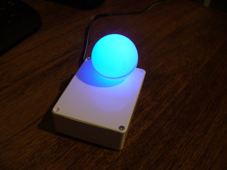
It reminds me of the giant killer orb “Rover” from “The Prisoner“… Using a minimal Arduino bootrom system, a DS1307 real time clock IC and an RGB diffused LED, you can make a clock that blinks the time, using the colours of the LED to note different numerical values.
For example, if the time is 12:45, the clock will blink red 12 times, then show blue for a second (think of this as the colon on a digital clock) then blink four times in green (for forty minutes), then blink three times in red for the individual minutes.
If there is a zero, blink blue quickly. Then the clock will not display anything for around forty seconds, then repeat the process. Here he (she, it?) is blinking the time:
Setting the clock is simple. It is set to start at 12:00 upon power up. So for the first use you have to wait until about five seconds before midday or midnight, then power it up. To save cost it doesn’t use a backup lithium battery on the real-time clock IC, but you could add one if required. So let’s get started.
The first thing to do was test the RGB LED for brightness levels, so I just connected it to the digital output pins of my Arduino-compatible board via suitable current-limiting resistors. Red, green and blue to D9, D10 and D11 respectively. Each LED is going to be different, so to ensure maximum brightness without causing any damage you need to calculate the appropriate resistor values.
This is quite easy, the formula is: resistor (ohms) = voltage drop / LED current So if you have a 5V supply, and LED that needs only 2 volts, and draws 20 milliamps (0.2 amps) , the calculation will be: resistor = (5-2)/0.02 = 150 ohms. To be safe I used 180 ohm resistors. The LED was tested with this simple sketch:
/*
  blinky LED test
 */

int red = 2;
int green = 3;
int blue = 4;
int d = 300;
void setup()
{
  pinMode(red, OUTPUT);
  pinMode(green, OUTPUT);
  pinMode(blue, OUTPUT);
}

void loop()
{
  digitalWrite(red, HIGH);
  delay(d);
  digitalWrite(red, LOW);
  delay(d);
  digitalWrite(green, HIGH);
  delay(d);
  digitalWrite(green, LOW);
  delay(d);
  digitalWrite(blue, HIGH);
  delay(d);
  digitalWrite(blue, LOW);
  delay(d);
}
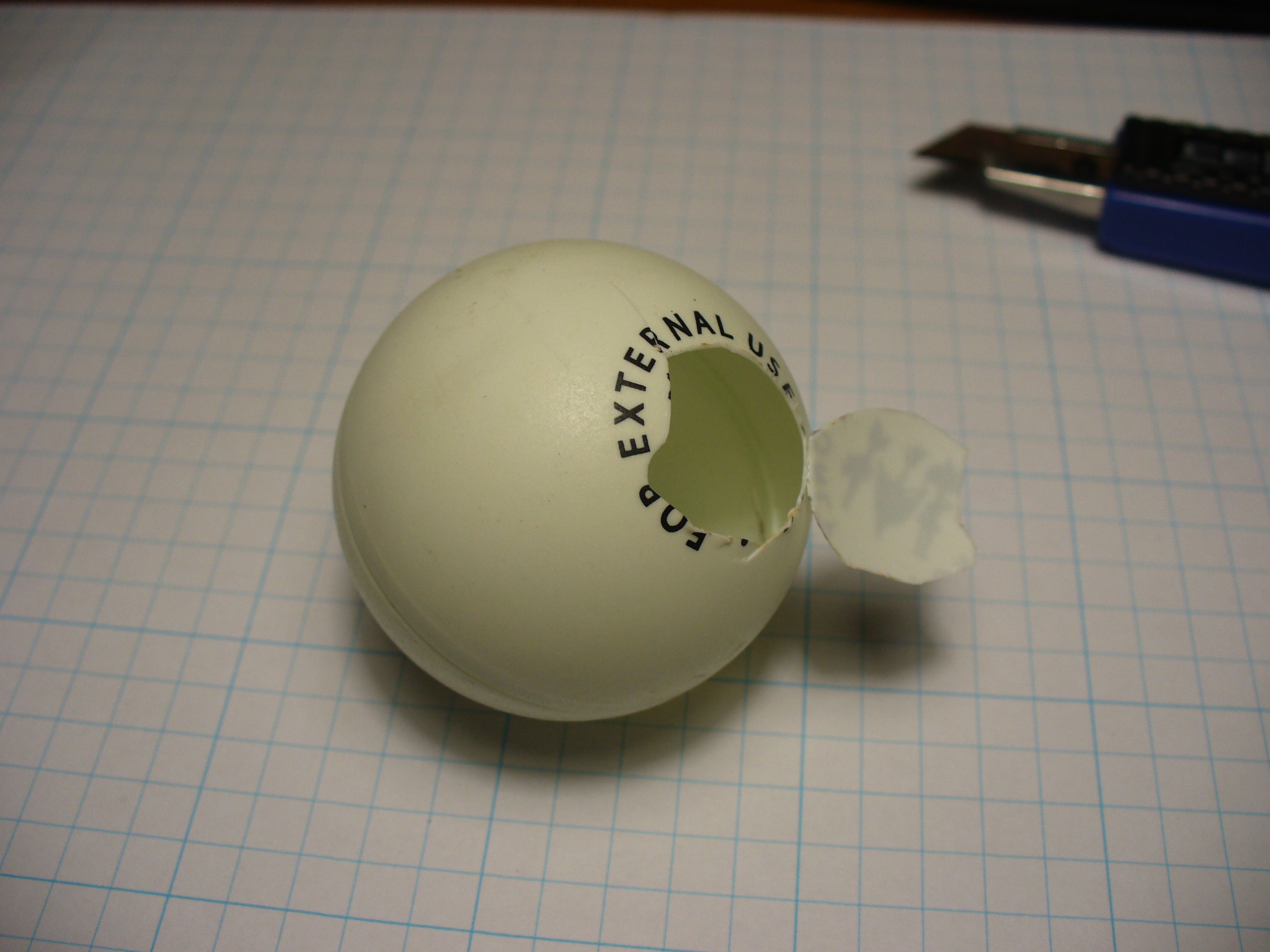
It was interesting to alter the value of d, the delay variable, to get an idea for an appropriate blinking speed. Originally the plan was to have the LED in a photo frame, but it was decided to mount a ping-pong ball over the LED for a retro-style look. Here is a short video of the result of the test:
If you are going to use a ping-pong ball, please be careful when cutting into it with a knife, initially it may require a lot of force, but once the knife cuts through it does so very quickly.
Now it was time to develop the sketch to convert time into blinks. The sketch itself is quite simple. Read the hours and minutes from the DS1307 timer IC; convert the hours to 12 hour time; then blink an LED for the number of hours, display another colour for the colon; divide the minutes by ten and blink that in another colour; then the modulus of minutes and ten to find the individual minutes, and blink those out. Here is the first test sketch:
/*
  "blinky" the one-eyed clock
  Version beta 1
  John Boxall August 2010/6th April 2022 - http://tronixstuff.com
  DS1307/i2c timekeeping based on code by Maurice Ribble 17-4-2008 -     http://www.glacialwanderer.com/hobbyrobotics
*/

#include "Wire.h"
#define DS1307_I2C_ADDRESS 0x68

int red = 9; // LEDs connected to these pins as you might want to PWM them to alter brightness
int green = 10;
int blue = 11;

// Convert normal decimal numbers to binary coded decimal
byte decToBcd(byte val)
{
  return ( (val / 10 * 16) + (val % 10) );
}

// Convert binary coded decimal to normal decimal numbers
byte bcdToDec(byte val)
{
  return ( (val / 16 * 10) + (val % 16) );
}

void setDateDs1307(byte second,        // 0-59
                   byte minute,        // 0-59
                   byte hour,          // 1-23
                   byte dayOfWeek,     // 1-7
                   byte dayOfMonth,    // 1-28/29/30/31
                   byte month,         // 1-12
                   byte year)          // 0-99
{
  Wire.beginTransmission(DS1307_I2C_ADDRESS);
  Wire.write(0);
  Wire.write(decToBcd(second));    // 0 to bit 7 starts the clock
  Wire.write(decToBcd(minute));
  Wire.write(decToBcd(hour));
  Wire.write(decToBcd(dayOfWeek));
  Wire.write(decToBcd(dayOfMonth));
  Wire.write(decToBcd(month));
  Wire.write(decToBcd(year));
  Wire.write(0x10); // sends 0x10 (hex) 00010000 (binary) to control register - turns on square wave
  Wire.endTransmission();
}

void getDateDs1307(byte *second,
                   byte *minute,
                   byte *hour,
                   byte *dayOfWeek,
                   byte *dayOfMonth,
                   byte *month,
                   byte *year)
{
  // Reset the register pointer
  Wire.beginTransmission(DS1307_I2C_ADDRESS);
  Wire.write(0);
  Wire.endTransmission();
  Wire.requestFrom(DS1307_I2C_ADDRESS, 7);
  *second     = bcdToDec(Wire.read() & 0x7f);
  *minute     = bcdToDec(Wire.read());
  *hour       = bcdToDec(Wire.read() & 0x3f);  // Need to change this if 12 hour am/pm
  *dayOfWeek  = bcdToDec(Wire.read());
  *dayOfMonth = bcdToDec(Wire.read());
  *month      = bcdToDec(Wire.read());
  *year       = bcdToDec(Wire.read());
}

void blinkLED(int colour, int ondelay, int offdelay, int blinks)
// blinks LED on pin 'colour' for 'blinks' times with on and off delay of 'ondelay', 'offdelay'
// colour: 9 is red, 10 is green, 11 is blue
{
  for (int a = 0; a < blinks; a++) {
    digitalWrite(colour, HIGH); delay(ondelay); digitalWrite(colour, LOW); delay(offdelay);
  }
}

void blinkTime() // blinks the time
{
  byte second, minute, hour, dayOfWeek, dayOfMonth, month, year;
  float aa;
  int bb;

  getDateDs1307(&second, &minute, &hour, &dayOfWeek, &dayOfMonth, &month, &year);
  // convert hours from 24 to 12 hour time
  if (hour == 0)
  {
    hour = 12;
  }
  if (hour > 12)
  {
    hour = hour - 12;
  }
  blinkLED(9, 500, 500, hour); // blink hours in red
  blinkLED(11, 1000, 500, 1); // show blue for one second
  aa = minute;
  aa = aa / 10;
  bb = int(aa); // find the value of tens of minutes (0~5)
  if (bb > 0)
  {
    blinkLED(10, 500, 500, bb); // blink tens of minutes
  }
  if (bb == 0) // but if the time is something like 03:02?
  {
    blinkLED(11, 200, 200, 1); // blink blue quickly for zero
  }
  aa = minute % 10; // find modulo of minutes to get single minutes
  if (bb > 0)
  {
    blinkLED(9, 500, 500, bb);
  }
  if (bb == 0)
  {
    blinkLED(11, 200, 200, 1); // blink blue quickly for zero
  }
}

void setup()
{
  byte second, minute, hour, dayOfWeek, dayOfMonth, month, year;
  Wire.begin();
  second = 0;
  minute = 17;
  hour = 4;
  dayOfWeek = 6; // these values are moot, but need to store something
  dayOfMonth = 28;
  month = 5;
  year = 10;
  setDateDs1307(second, minute, hour, dayOfWeek, dayOfMonth, month, year);
  pinMode(red, OUTPUT);
  pinMode(green, OUTPUT);
  pinMode(blue, OUTPUT);
}

void loop()
{
  blinkTime();
  delay(5000);
}
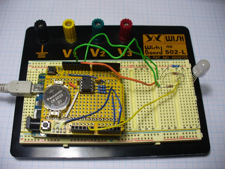
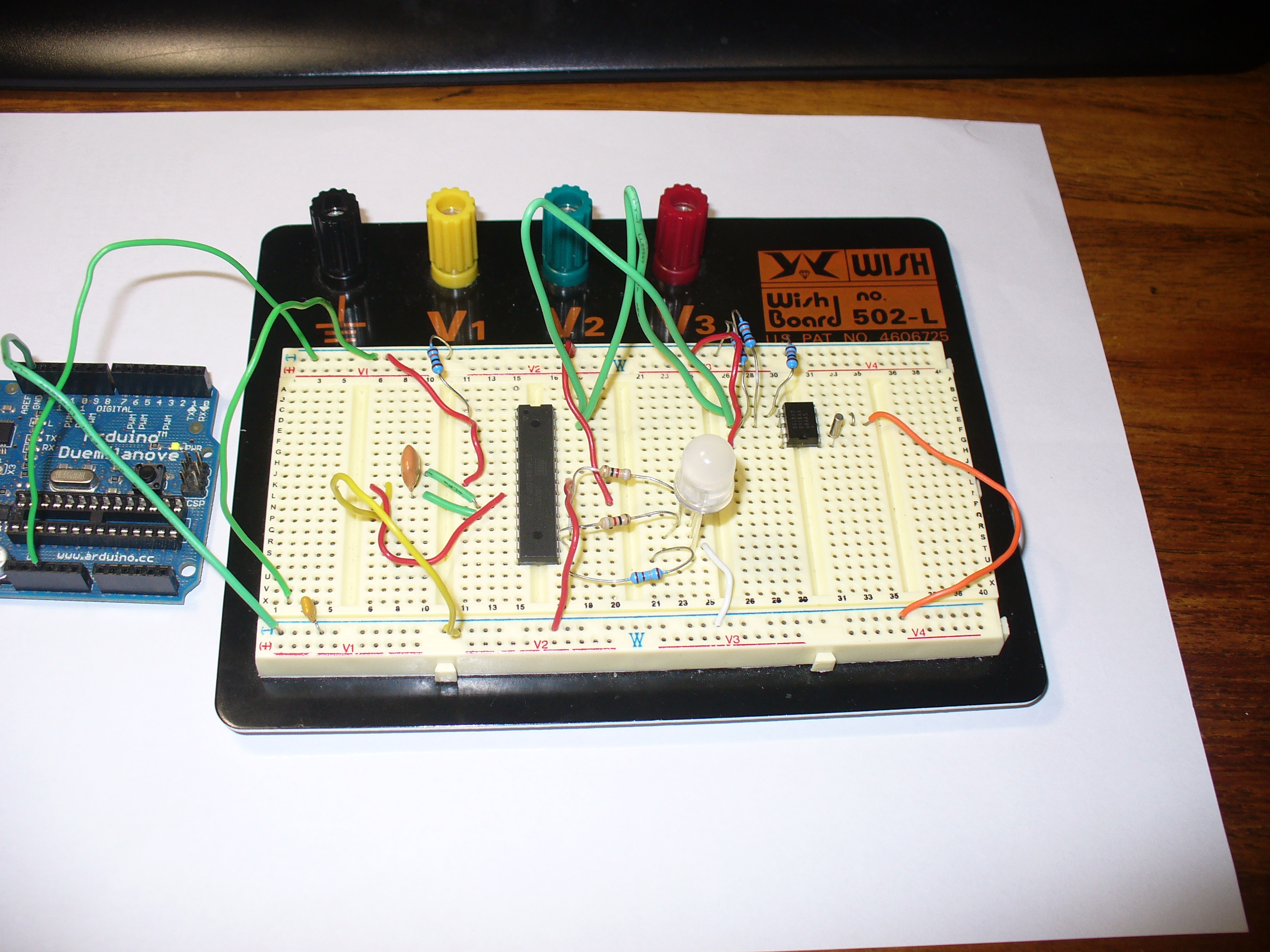
Finally, the code was tested using the Arduino-compatible board and my home-made DS1307 real time clock shield (hey it was 2010, DS32xx were expensive). It is best to use existing hardware while testing, before committing to purchasing new hardware and so on. So here it is on the breadboard:
Here is the prototype in action:
If you’re wondering why the videos are potato-cam quality, smartphones couldn’t record using 4K Ultra HD in 2010.
But perhaps the first version was a little bland. By using analogWrite() we can control the brightness of the LED segments. So I’ve added two more functions, whiteGlow() and blueGlow(); whose purpose is to make the display “glow” by increasing then decreasing the brightness.
And I’ve scaled back the amount of blinking, to make blinky less obvious. So now the display will glow white to announce the forthcoming display of time, wait a second, blink the time (with a blue glowing colon) then stay dark for ten seconds before repeating the process. Here is a quick demonstration of this display style:
Here is the sketch for the above demonstration, and the final one I will use with the hardware prototype:
/*
  "blinky" the one-eyed clock - Version 2.1
  John Boxall 04 August 2010/6th April 2022
  IDGAF licence
  DS1307/i2c timekeeping based on code by Maurice Ribble
  17-4-2008 - http://www.glacialwanderer.com/hobbyrobotics
*/

#include "Wire.h"
#define DS1307_I2C_ADDRESS 0x68

int red = 9; // LEDs connected to these pins as you might want to PWM them to alter brightness
int green = 10;
int blue = 11;

// Convert normal decimal numbers to binary coded decimal
byte decToBcd(byte val)
{
  return ( (val / 10 * 16) + (val % 10) );
}

// Convert binary coded decimal to normal decimal numbers
byte bcdToDec(byte val)
{
  return ( (val / 16 * 10) + (val % 16) );
}

void setDateDs1307(byte second,        // 0-59
                   byte minute,        // 0-59
                   byte hour,          // 1-23
                   byte dayOfWeek,     // 1-7
                   byte dayOfMonth,    // 1-28/29/30/31
                   byte month,         // 1-12
                   byte year)          // 0-99
{
  Wire.beginTransmission(DS1307_I2C_ADDRESS);
  Wire.write(0);
  Wire.write(decToBcd(second));    // 0 to bit 7 starts the clock
  Wire.write(decToBcd(minute));
  Wire.write(decToBcd(hour));
  Wire.write(decToBcd(dayOfWeek));
  Wire.write(decToBcd(dayOfMonth));
  Wire.write(decToBcd(month));
  Wire.write(decToBcd(year));
  Wire.write(0x10); // sends 0x10 (hex) 00010000 (binary) to control register - turns on square wave
  Wire.endTransmission();
}

void getDateDs1307(byte *second,
                   byte *minute,
                   byte *hour,
                   byte *dayOfWeek,
                   byte *dayOfMonth,
                   byte *month,
                   byte *year)
{
  // Reset the register pointer
  Wire.beginTransmission(DS1307_I2C_ADDRESS);
  Wire.write(0);
  Wire.endTransmission();
  Wire.requestFrom(DS1307_I2C_ADDRESS, 7);
  *second     = bcdToDec(Wire.read() & 0x7f);
  *minute     = bcdToDec(Wire.read());
  *hour       = bcdToDec(Wire.read() & 0x3f);  // Need to change this if 12 hour am/pm
  *dayOfWeek  = bcdToDec(Wire.read());
  *dayOfMonth = bcdToDec(Wire.read());
  *month      = bcdToDec(Wire.read());
  *year       = bcdToDec(Wire.read());
}

void blinkLED(int colour, int ondelay, int offdelay, int blinks)
// blinks LED on pin 'colour' for 'blinks' times with on and off delay of 'ondelay', 'offdelay'
// colour: 9 is red, 10 is green, 11 is blue
{

  for (int a = 0; a < blinks; a++)
  {
    digitalWrite(colour, HIGH);
    delay(ondelay);
    digitalWrite(colour, LOW);
    delay(offdelay);
  }
}

void blinkTime()
// blinks the time
{
  byte second, minute, hour, dayOfWeek, dayOfMonth, month, year;
  float aa;
  int bb;
  getDateDs1307(&second, &minute, &hour, &dayOfWeek, &dayOfMonth, &month, &year);

  // convert hours from 24 to 12 hour time
  if (hour == 0)
  {
    hour = 12;
  }
  if (hour > 12)
  {
    hour = hour - 12;
  }
  blinkLED(9, 500, 500, hour); // blink hours in red
  blueGlow(1, 10);
  aa = minute;
  aa = aa / 10;
  bb = int(aa); // find the value of tens of minutes (0~5)
  if (bb > 0)
  {
    blinkLED(10, 500, 500, bb); // blink tens of minutes
  }
  if (bb == 0) // but if the time is something like 03:02?
  {
    blinkLED(11, 200, 200, 1); // blink blue quickly for zero
  }
  aa = minute % 10; // find modulo of minutes to get single minutes
  bb = aa;
  if (bb > 0)
  {
    blinkLED(9, 500, 500, bb); // blink tens of minutes
  }
  if (bb == 0)
  {
    blinkLED(11, 200, 200, 1); // blink blue quickly for zero
  }
}

void whiteGlow(int n, int d)
{
  for (int nn = 0; nn < n; nn++)
  {
    for (int a = 0; a <= 255; a++)
    {
      analogWrite(red, a);
      analogWrite(green, a);
      analogWrite(blue, a);
      delay(d);
    }
    for (int a = 255; a >= 0; --a)
    {
      analogWrite(red, a);
      analogWrite(green, a);
      analogWrite(blue, a);
      delay(d);
    }
  }
}

void blueGlow(int n, int d)
{
  for (int nn = 0; nn < n; nn++)
  {
    for (int a = 0; a <= 255; a++)
    {
      analogWrite(blue, a);
      delay(d);
    }
    for (int a = 255; a >= 0; --a)
    {
      analogWrite(blue, a);
      delay(d);
    }
  }
}

void setup()
{
  byte second, minute, hour, dayOfWeek, dayOfMonth, month, year;
  Wire.begin();
  second = 0;
  minute = 17;
  hour = 4;
  dayOfWeek = 6; // these values are moot, but need to store something
  dayOfMonth = 28;
  month = 5;
  year = 10;
  setDateDs1307(second, minute, hour, dayOfWeek, dayOfMonth, month, year); // every time blinky has new batteries, it will start from midnight/midday
  pinMode(red, OUTPUT);
  pinMode(green, OUTPUT);
  pinMode(blue, OUTPUT);
}

void loop()
{
  whiteGlow(1, 10); // glow white - announces that the time will now be shown
  delay(1000); // give people a second to focus on blinky
  blinkTime();
  delay(50000); // wait 50 seconds
}
Once happy with the sketch, I put a fresh ATmega328P-PU with Arduino bootloader in the board and programmed it with the sketch, to be used in the final version. The next step is to build my own hardware. The last hardware unknown is the amount of current the circuit draws. Once I know this the correct voltage regulator and power supply can be decided upon.
I had a fair idea it would be less than 100 milliamps, so I put a 6V battery onto supply duty via a 78L05 5V regulator (data sheet), and recorded the result:
So it varies, between 20.5 and 46 mA. As it only reaches 46 mA for a short time, we could consider the constant draw to be averaged out at 30 mA. I really want this to be able to run from a battery, but without having an external lead-acid battery lurking around, it will need a plug-pack with an output voltage greater than 7V DC.
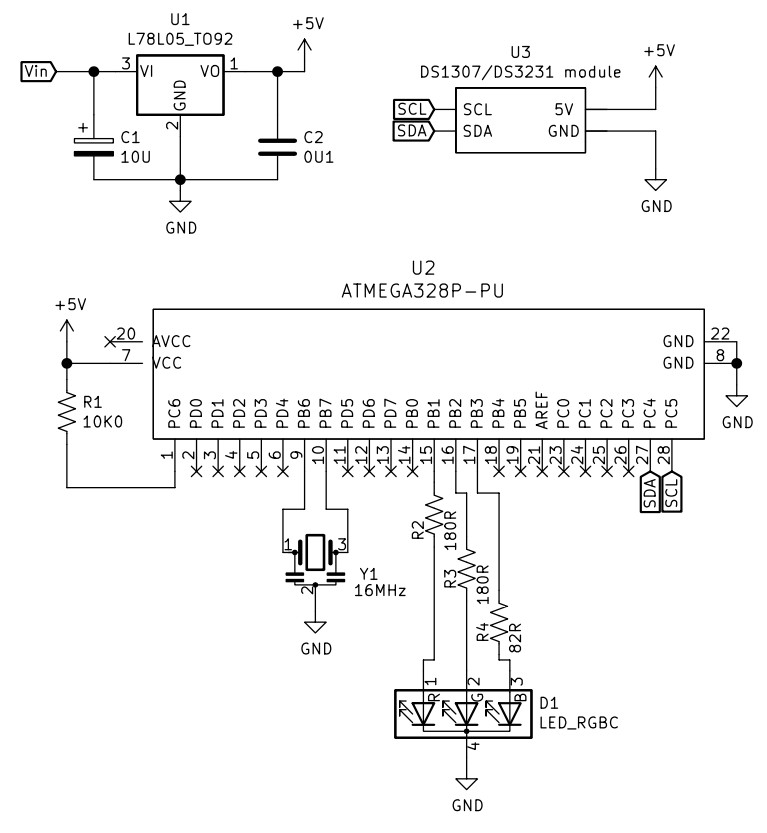
Another alternative would be to run it from a USB socket, a nice source of 5V. If doing so, there wouldn’t be a need for the 78L05 regulator. Which brings us to the circuit diagram, which includes the power regulator. I’ve also altered the resistors to suit the RGB LED used, your values may be different:
And since it’s 2022, not 2010 – I’ve replaced the DS1307 circuit with a RTC module. Y1 is a three pin 16MHz ceramic resonator, we used those in 2010 as they were cheaper and easier than a crystal and two 22pF capacitors.
The circuit does not allow for uploading code, so you will need to program the microcontroller on another Arduino or compatible board, then transfer it to the blinky circuit board as described above. At this stage you should test it again – but using a solderless breadboard. In doing so you can make final hardware checks, and generally make sure everything works as it should. This is also a good stage to double-check you are happy with the display behaviour, default time and so on.
Used the Duemilanove as a lazy 5V for testing.
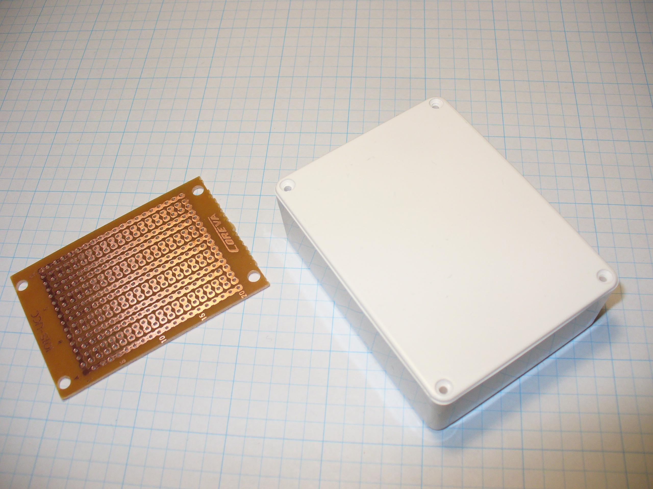
Time to solder up the circuit on some stripboard. Blank stripboard varies, but luckily I found this and a nice box to hold it in:
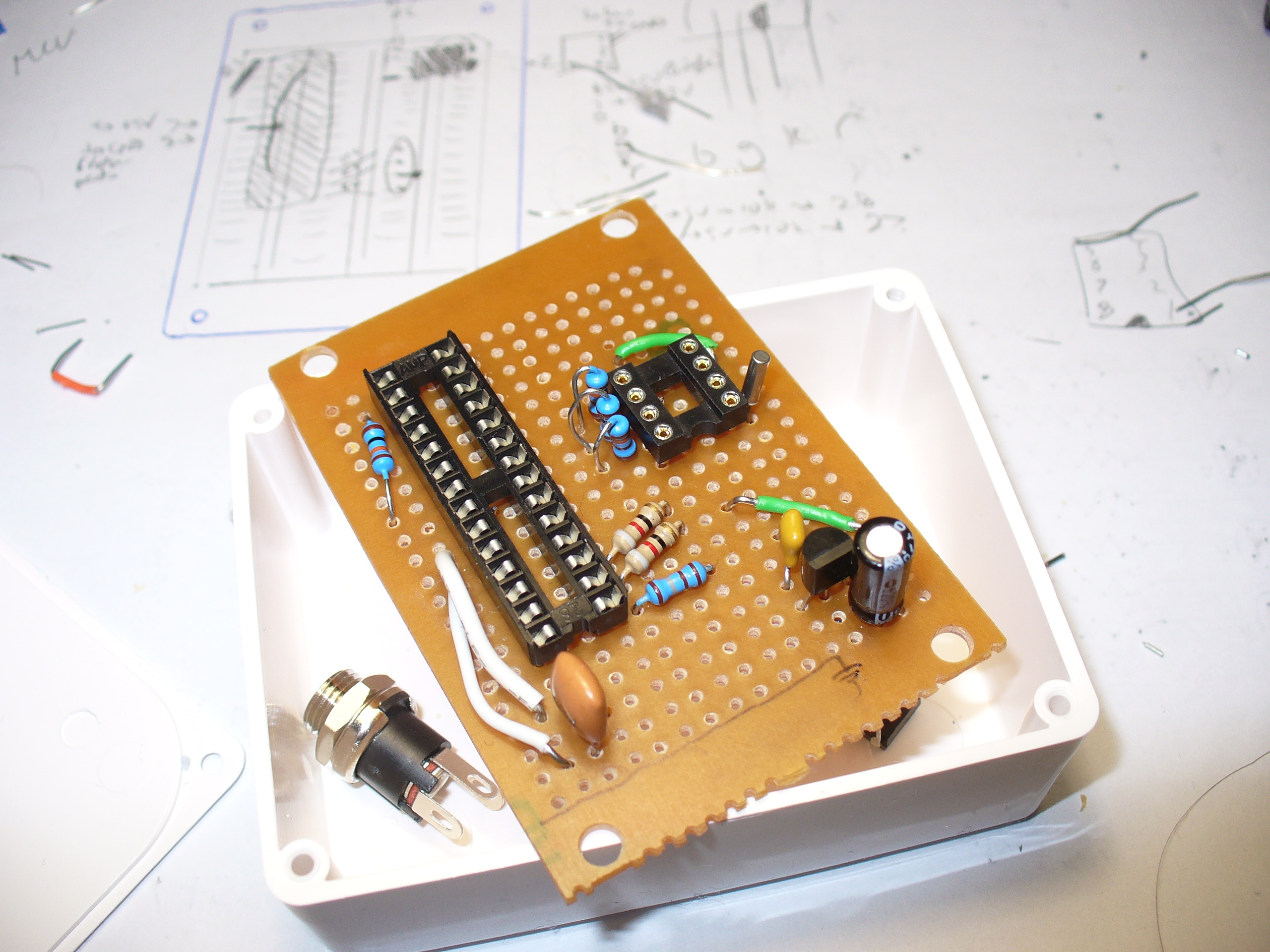
Stripboard does vary between retailers and so on, so you will need to work out the layout with your own board. In doing so, please double-check your work – follow the layout against the schematic and so on.
Have a break, then check it again. There is nothing worse than soldering away to realise you are one strip too far over or something. My hand-eye coordination is not the best, therefore my soldering isn’t pretty, but it works:
Note that the images above are using the 2010 circuit – which had a DS1307 sub-circuit.
One would say that there is a good argument for making your own PCBs… and I would agree with that. In 2010 it wasn’t that easy or inexpensive. Now you have KiCAD and Chinese PCB fabs tripping over themselves to give you cheap boards.
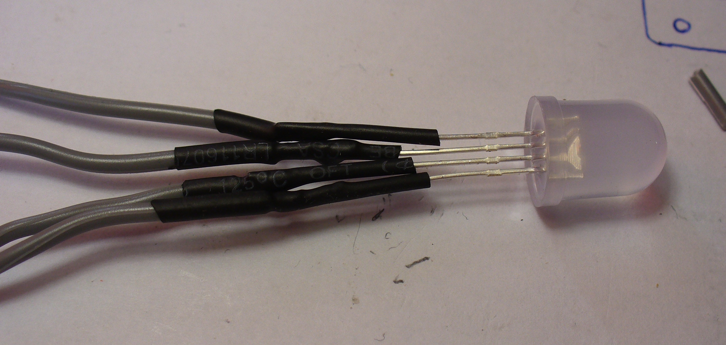
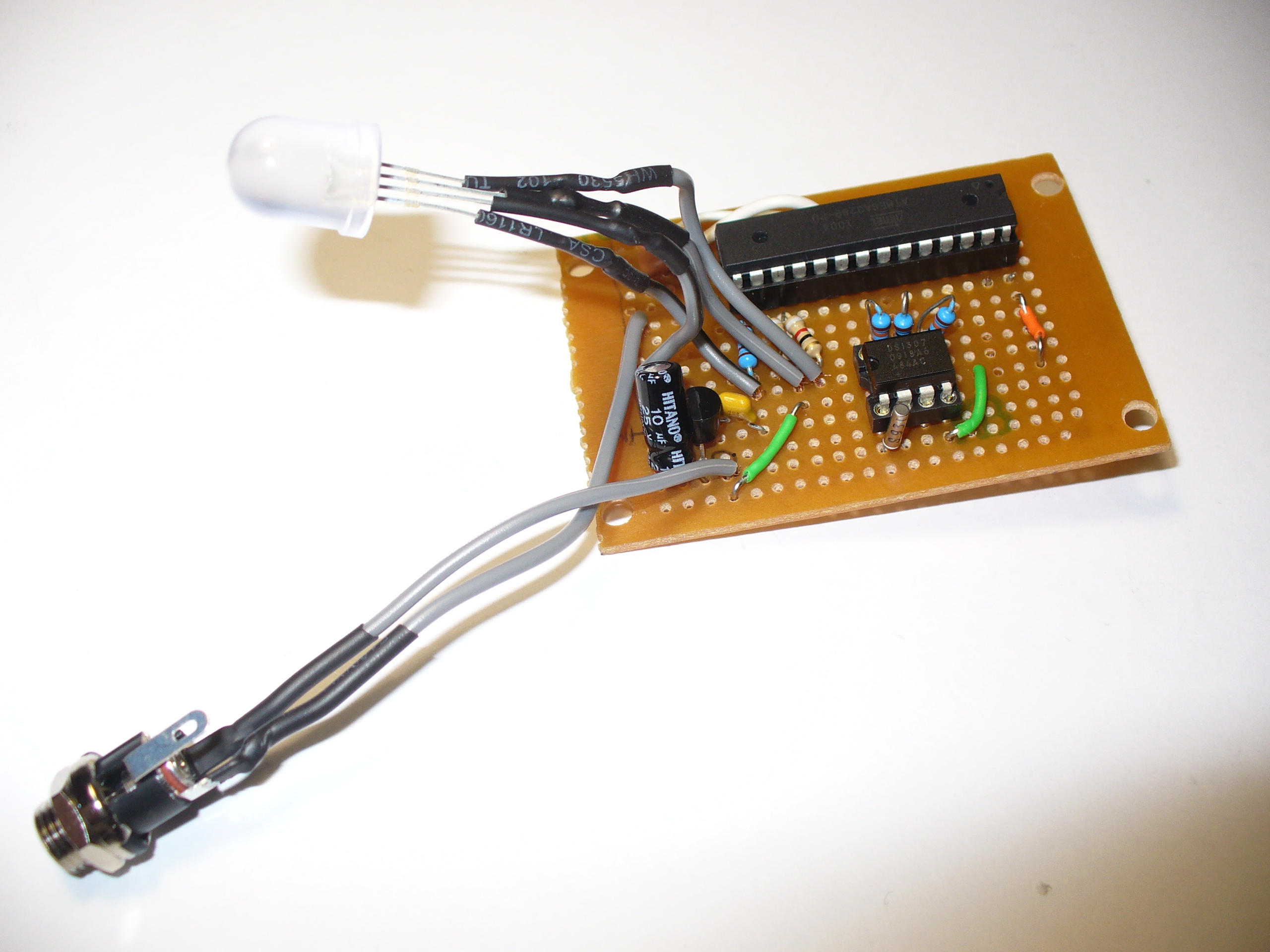
The LED is soldered to some short leads to give it a bit of play, and some heatshrink over the legs to keep them isolated:
And finally, to add a DC socket to feed blinky some power:
The last thing was to check the soldering once more under natural light, to check for bridges or shorts, then have a cup of tea. Upon my return I drilled out a hole in the enclosure lid for the LED, and one one the side for the DC socket, and fitted the lot together… and success! It worked.
I hope you enjoyed making this or at least reading about it. If you find this sort of thing interesting, please consider ordering one or both of my books from No Starch Press, or other book sellers:
Block disclosed today that a security breach involving a former employee impacts 8.2 million Cash App users. In an SEC filing, the company reported that an ex-employee on December 10th downloaded a number of reports with information on customer information. The exfiltrated data included full names, brokerage account numbers, brokerage portfolio value, brokerage portfolio holdings and reports of stock trading activity.
According to the filing, only customers that used Cash App’s stock function are potentially included in the breach. While Cash App got its start as a peer-to-peer payment app, its customers can also use it to buy stocks and Bitcoin. No other Cash App features outside of stocks were involved in the breach, nor did it include any customers outside of the US, according to the company.
“The reports did not include usernames or passwords, Social Security numbers, date of birth, payment card information, addresses, bank account information, or any other personally identifiable information. They also did not include any security code, access code, or password used to access Cash App accounts. Other Cash App products and features (other than stock activity) and customers outside of the United States were not impacted,” wrote Block in the filing.
Block has launched a formal investigation into the incident and has contacted law enforcement. It also plans on notifying all 8.2 million customers involved in the breach by email.
According to the filing, the ex-employee once had access to the customer information as an employee at CashApp. But by the time the breach occurred, they had already been gone from the company for several months. It’s unclear how a former employee was still able to retrieve such highly sensitive information. Engadget has reached out to Block for a response, and will update if we hear back.