wsduino revision 2
Honestly, I think the hacking required to add buttons for hours and minutes to the Rothko clock is messy. But if you want an easy, quick and intuitive way to set the time, there is no alternative for buttons; remote control (IR, XBee, BT) would require extra devices, GPS or NTP would need settings. Since the Nixie shield board is already overcrowded, the logical place for the buttons would be on wsduino. And this is the main reason I had to redesign it.
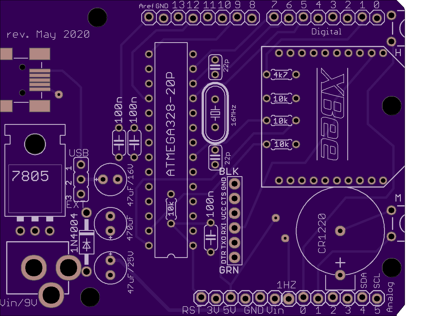
I opted for two right-angle tactile switches placed on the right side of the board, above and below the XBee module. These switches, connected to A0 and A1, are intended mostly for clock functionality, optional for other applications. They could also be replaced by wired external (panel-mounted, not on-board) buttons, when an enclosure is used.
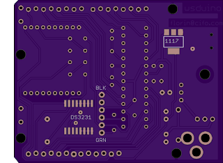
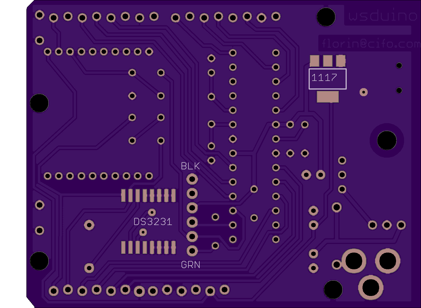
This is how the new wsduino board looks.

Other improvements are:
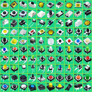
The switch that fits wsduino is number 24 in the chart below (used by sellers on ebay):
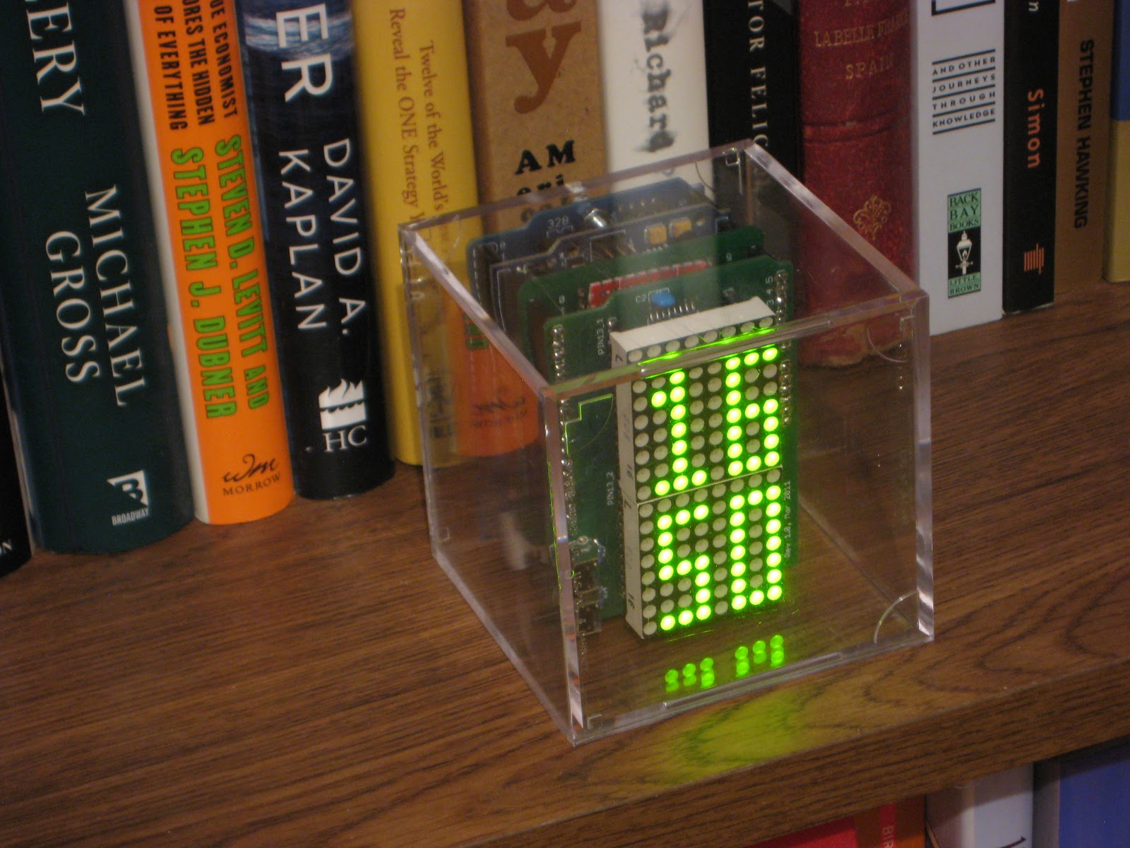
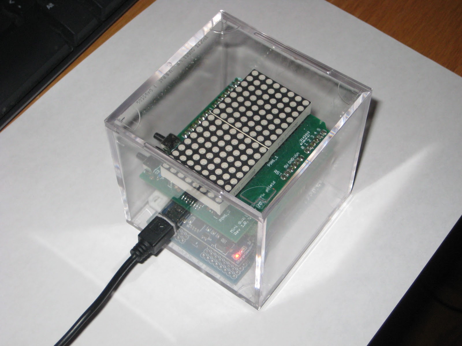
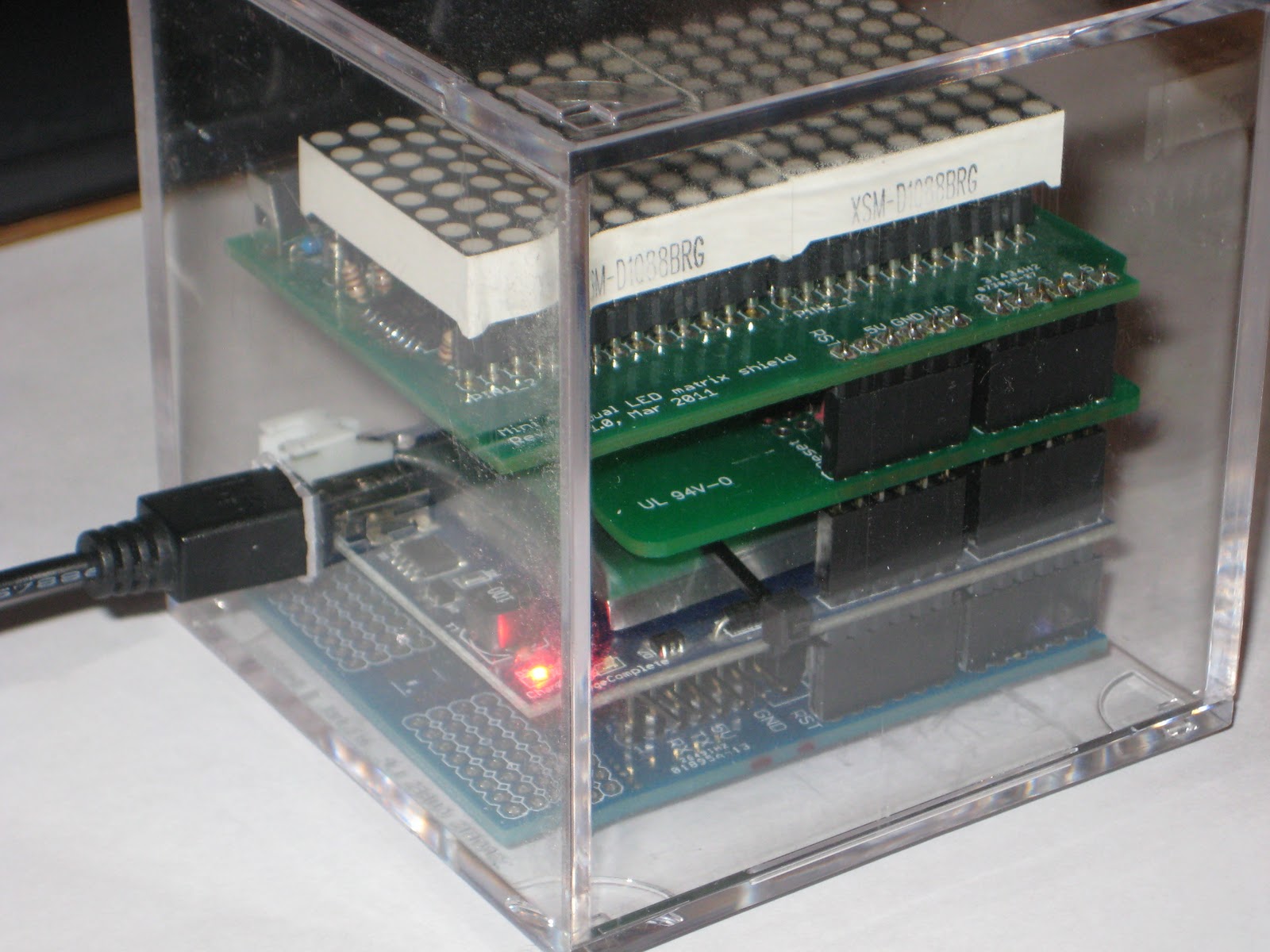
To recap, wsduino is the arduino-compatible board with DS3231 RTC and XBee support. To build a clock, just add a display shield like the 6-character LED display, the bicolor LED matrix shield ("Mondrian clock") or the 6-tube Nixie shield ("Rothko clock").
I opted for two right-angle tactile switches placed on the right side of the board, above and below the XBee module. These switches, connected to A0 and A1, are intended mostly for clock functionality, optional for other applications. They could also be replaced by wired external (panel-mounted, not on-board) buttons, when an enclosure is used.
This is how the new wsduino board looks.
Other improvements are:
- moved the 3V3 regulator for better heat dissipation (it was on the opposite side of 7805);
- moved the electrolytic capacitors around, to allow for easier removal of the processor from the socket;
- moved the 1Hz output to a pin between the banks of analog and power pins;
- removed the SDA and SCL from the top bank of digital pins (they were redundant anyway, plus makes more room for the screw and nut);
The switch that fits wsduino is number 24 in the chart below (used by sellers on ebay):

To recap, wsduino is the arduino-compatible board with DS3231 RTC and XBee support. To build a clock, just add a display shield like the 6-character LED display, the bicolor LED matrix shield ("Mondrian clock") or the 6-tube Nixie shield ("Rothko clock").