Mondrian clock software release
Unbelievably, there is still demand for the Dual LED matrix shield for Arduino, which also pressures me to maintain and upgrade the supporting software, usually on client's request.
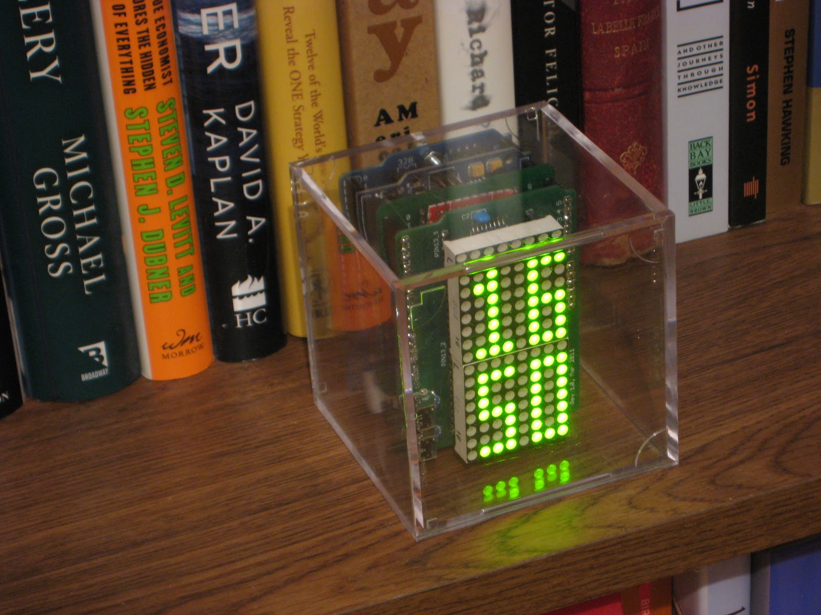
And that is how the Mondrian clock got a couple of new display modes: one picked directly from the Cube clock, showing just hours and minutes, the other one an improvement of the same, with the addition of a red dot moving around the rectangular clock face to indicate the seconds.
The display mode changes when both buttons are pressed simultaneously.
Here is the clock in action.
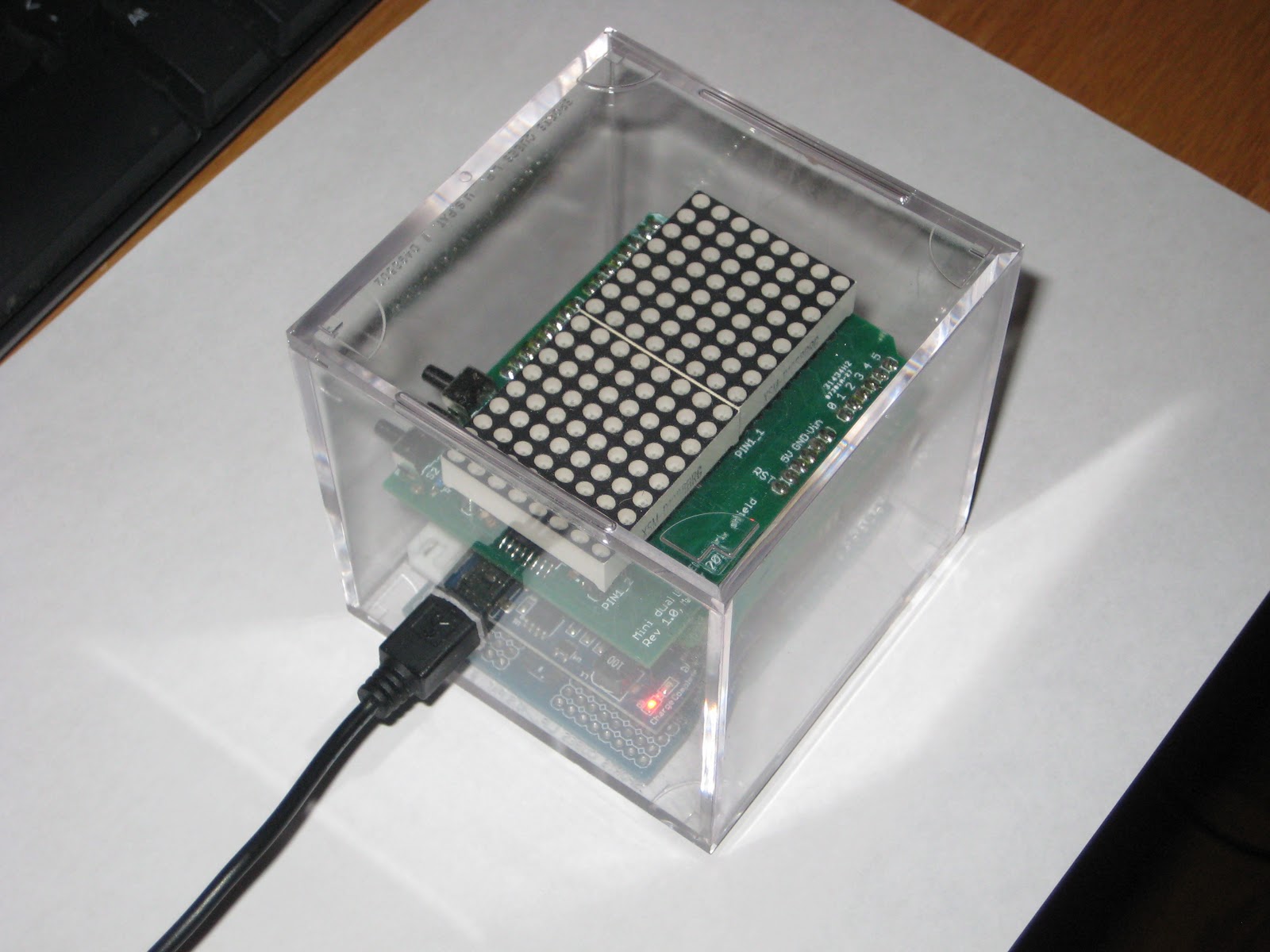
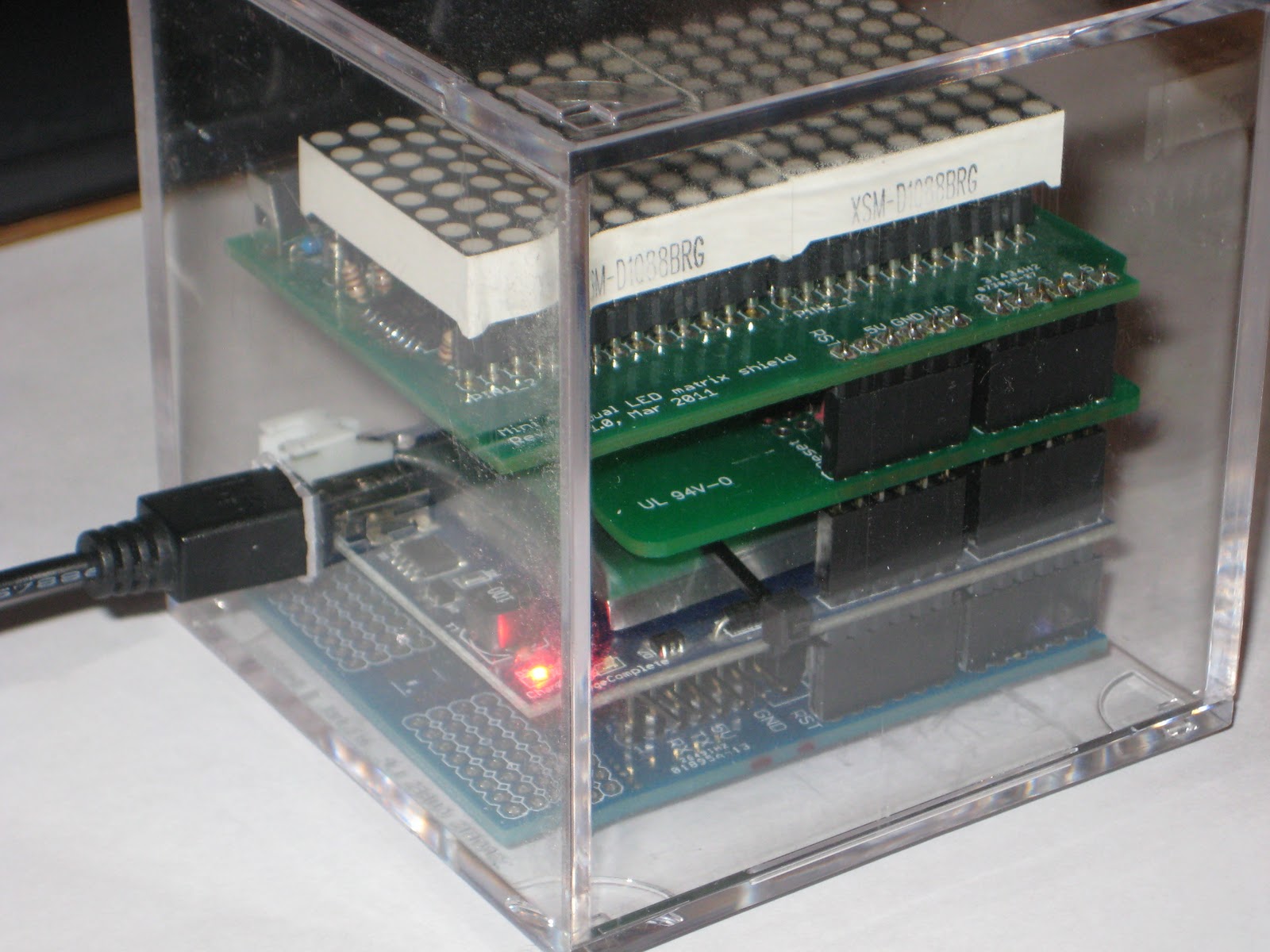
The Mondrian clock uses the Dual LED matrix shield and wsduino (as an RTC-equipped and XBee-supporting Arduino-compatible).
The code is available here. There is no GPS support, but that can be copied and adapted from the previous version of Mondrian software.
Note that the LED matrix shield was designed to accommodate either the common-anode or the common-cathode LED matrices, by soldering the correct LED driver, either A2982 or ULN2803 respectively. In the software, use either one of these defines:
#define _COMMON_ANODE_
//#define _COMMON_CATHODE_
The only user interface on the shield is the pair of buttons. Pressing the left one will increment the hours, the right one will increment the minutes, while the seconds are always reset.
By pressing both buttons at once, the display mode cycles through Mondrian mode (red hours, green minutes, orange seconds), 24-hour mode (HH:MM in green), 12-hour mode (HH:MM in orange), and moving second red dot (12-hour, HH:MM in green, more square font).
And that is how the Mondrian clock got a couple of new display modes: one picked directly from the Cube clock, showing just hours and minutes, the other one an improvement of the same, with the addition of a red dot moving around the rectangular clock face to indicate the seconds.
The display mode changes when both buttons are pressed simultaneously.
Here is the clock in action.
The Mondrian clock uses the Dual LED matrix shield and wsduino (as an RTC-equipped and XBee-supporting Arduino-compatible).
The code is available here. There is no GPS support, but that can be copied and adapted from the previous version of Mondrian software.
Note that the LED matrix shield was designed to accommodate either the common-anode or the common-cathode LED matrices, by soldering the correct LED driver, either A2982 or ULN2803 respectively. In the software, use either one of these defines:
#define _COMMON_ANODE_
//#define _COMMON_CATHODE_
By pressing both buttons at once, the display mode cycles through Mondrian mode (red hours, green minutes, orange seconds), 24-hour mode (HH:MM in green), 12-hour mode (HH:MM in orange), and moving second red dot (12-hour, HH:MM in green, more square font).