Description
This is an Arduino based home security project that uses the power of "Cayenne" for extraordinary capabilities.
Cayenne Beta
Cayenne is a new IoT drag and drop platform originally released for the Raspberry Pi, but now available for Arduino. Cayenne makes the task of connecting your Arduino to the internet as simple as possible. All of the complexity of internet connectivity is hidden within the Cayenne library.
You can easily create a Network of Arduinos and build an IoT system which can be managed and operated within the Cayenne dashboard. This dashboard is accessible through your browser or via the Cayenne smart phone app (on IOS or Android).
The feature I liked the most, was the ability to change the position of sensors or actuators on the Arduino without having to re-upload Arduino code. I could manage the changed position from within the Cayenne platform. The other feature that I liked was the ability to setup actions based on custom triggers. You can use Cayenne to trigger a whole range of functions, for example: play a sound, move a motor, light up an LED, or to send alert notifications via email or SMS.
Cayenne is in Beta at the moment, so there are a few minor bugs here and there, but overall - I give it a thumbs up - it is definitely worth checking out.
Source: myDevices Media Kit
Home Security Project Summary
In order to fully experience this new IoT platform, I decided to create a project to really put it through its paces. This is what my Security Project will need:
- It will use two Arduinos, one connected to the internet via an Ethernet shield, and the other via WIFI.
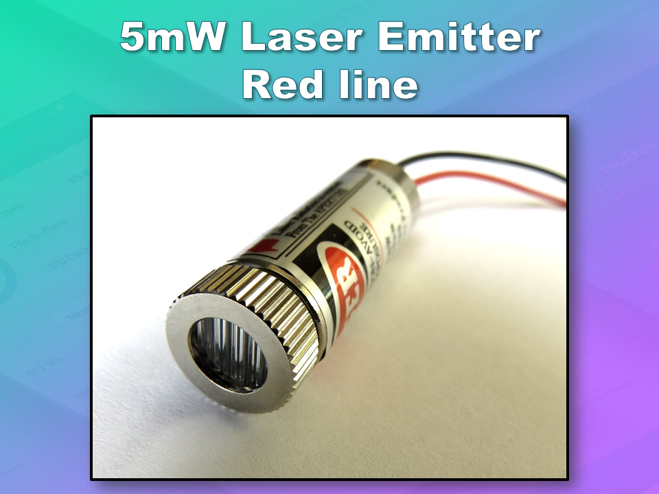
- Two detectors - a PIR sensor and a laser trip wire.
- If the sensors are tripped, the person has 10 seconds to present an RFID tag to the Grove RFID reader:
- If a valid RFID tag is SUCCESSFULLY presented within the time limit, a nice personalised greeting will be played to that person using a Grove - Serial MP3 player
- If a valid RFID FAILS to be presented within the time limit, an Alarm will sound, and I will be notified of the intrusion via an SMS alert.
- The Cayenne dashboard will show the status of the sensors, and I will have full control over my security system via the web interface (or smartphone app).
- The sensors will be attached to a different Arduino to that of the Grove MP3 player and the RFID tag reader, which means that there will have to be some level of communication between the two Arduinos. In fact, the cross communication will be vital to the success of this project.
Project Video
Flow Diagrams:
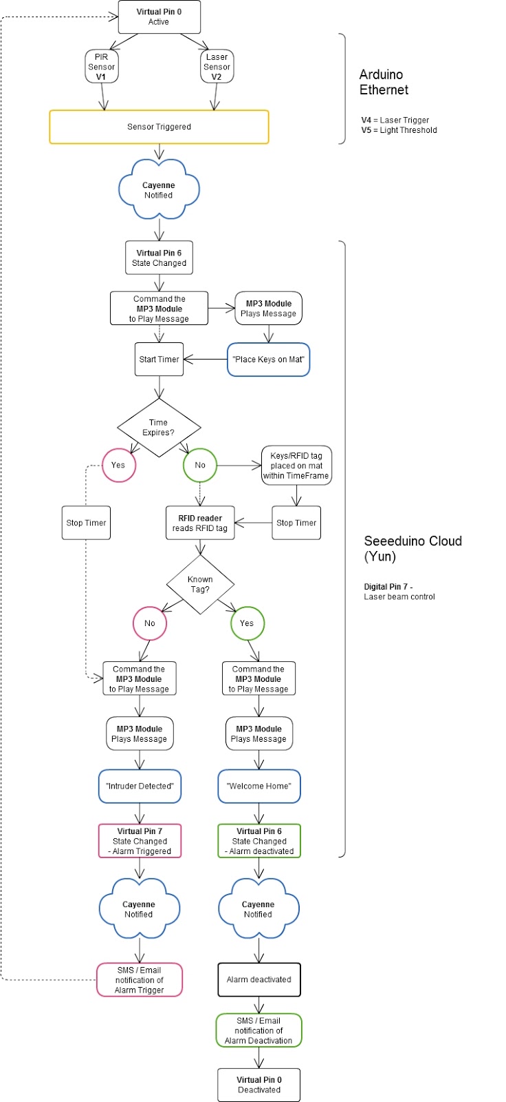
Main Flow Diagram
The following flow diagram shows the Security project process. It is a high level view of the decisions being made by each Arduino in response to various events.
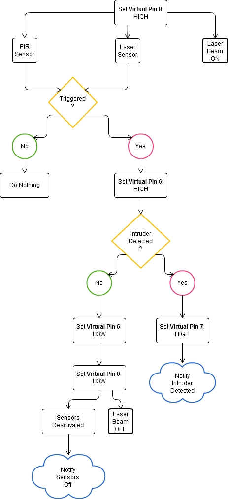
Triggers Flow Diagram
The following flow diagram aims to highlight the various triggers set up within Cayenne to get this Security system to work.
Arduino IDE and Library Downloads
You will need an Arduino IDE to upload code to the Arduino and the Seeeduino Cloud.
Here is the link to the Arduino IDE: Arduino IDE - download location
The Cayenne service requires that you download and install the Cayenne Library into your Arduino IDE.
You can get the Cayenne Library from here: Cayenne Library File - Download
Cayenne Connectivity Setup
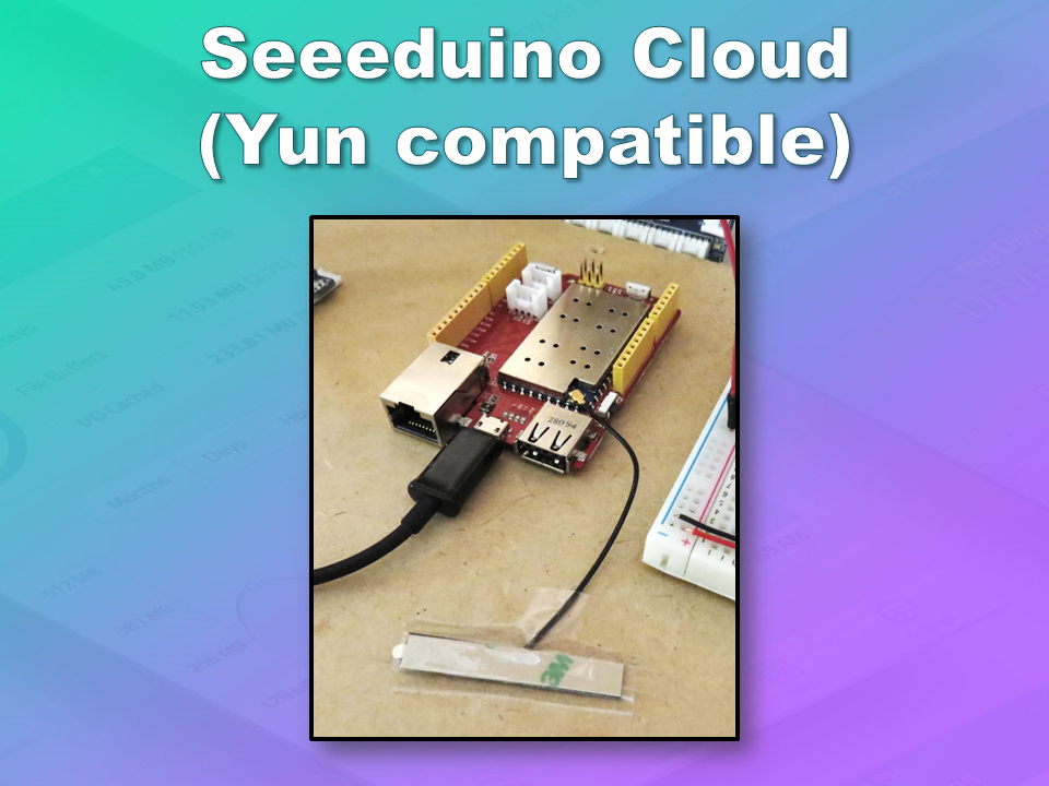
The Seeeduino Cloud needs to be prepared for use with Cayenne.
Normal operating/setup instructions can be found here: Seeeduino Cloud WIKI page
Once you have successfully connected Seeeduino Cloud to your WIFI network, you can add it to the Cayenne Dashboard by making the following selections from within the Cayenne Web application:
- Add New
- Device/Widget
- Microcontrollers
- Arduino
- Ensure Seeeduino Cloud is connected to WIFI network - the select the NEXT button
- Select - Arduino Yun: Built-in Ethernet - ticked
- Providing you have already installed the Cayenne library as described above - you should be able to copy and paste the code to the Arduino IDE and upload to the Seeeduino Cloud.
- If successful, you should see the Arduino Yun board appear within the Cayenne Dashboard. If not, then seek help within the Cayenne forum.
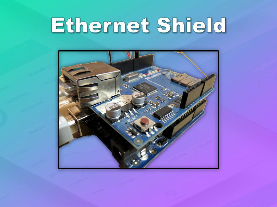
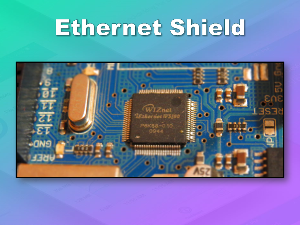
The Arduino UNO with WIZNET 5100 - Ethernet Shield
also needs to be prepared with Cayenne
- Add New
- Device/Widget
- Microcontrollers
- Arduino
- Ensure Arduino is powered, and Ethernet shield is connected to your internet router via an Ethernet cable
- Select - Arduino Uno: Ethernet Shield W5100 - ticked
- Copy and paste the code to the Arduino IDE and upload to the Arduino UNO.
- If successful, you should see the Arduino Uno board appear within the Cayenne Dashboard. If not, then seek help within the Cayenne forum.
If you have the Ethernet shield with the WIZNET 5200 chip, then you may need to download a specific
Ethernet library in addition to the Cayenne library.
Just follow the instructions within the Automatically generated sketch provided - when you select your specific Arduino/Ethernet/WIFI shield combination. If you need further instructions on connecting your device to Cayenne - then please visit the
myDevices website for the online documentation.
ARDUINO CODE (1)
Code for Arduino UNO with Ethernet Shield:
The following code will need to be uploaded to the Arduino UNO:
ARDUINO CODE (2)
Code for Seeeduino Cloud:
The following code will need to be uploaded to the Seeeduino Cloud:
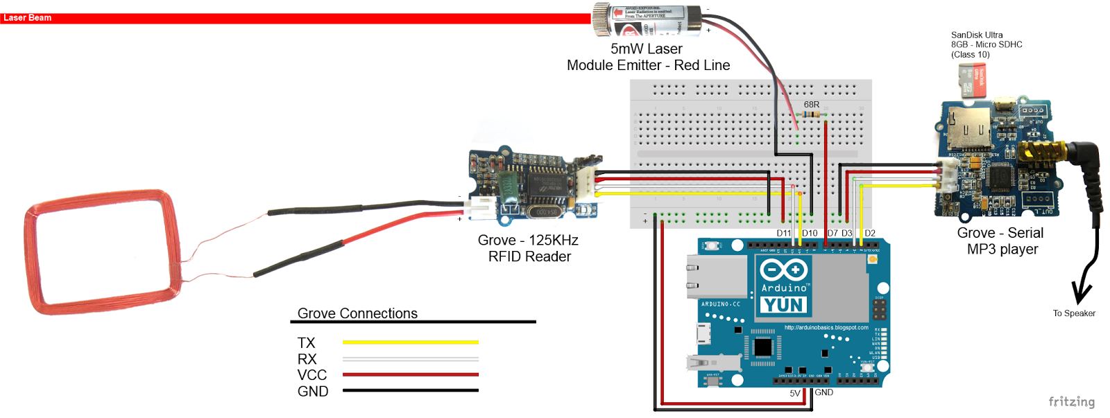
Fritzing diagram (1)
Fritzing diagram for Arduino UNO with Ethernet
Please click on the picture below for an enlarged version of this fritzing diagram
Fritzing diagram (2)
Fritzing diagram for Seeeduino Cloud
Please click on the picture below for an enlarged version of this fritzing diagram
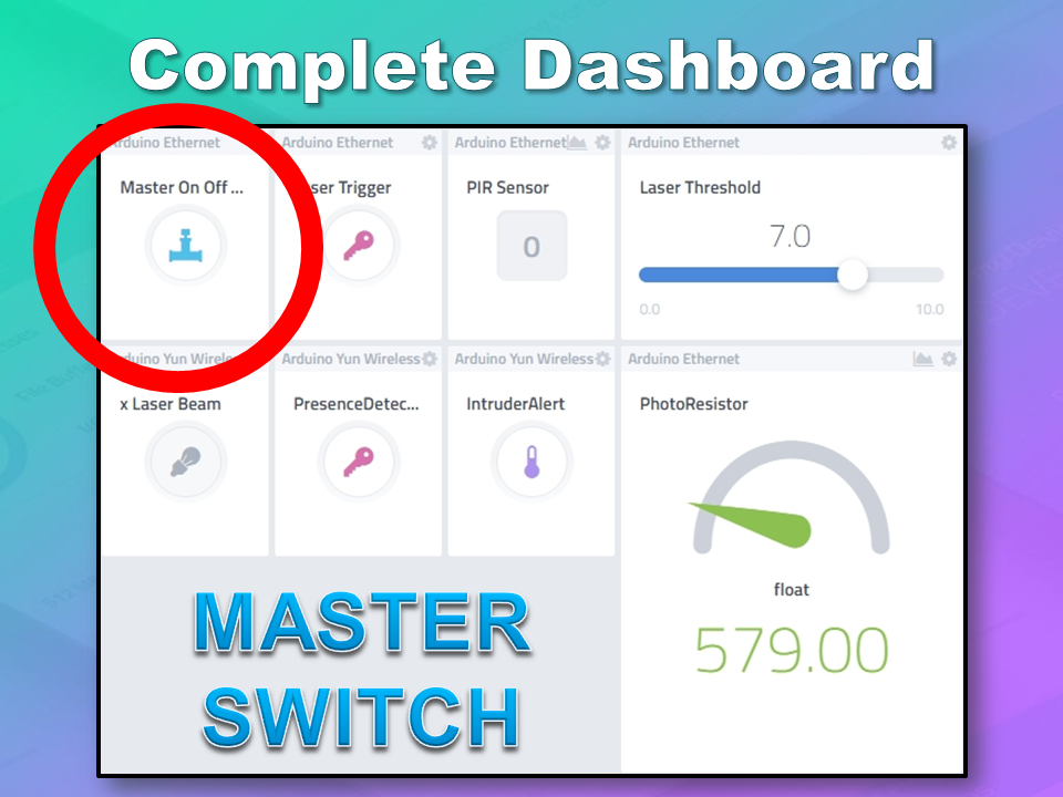
Cayenne Dashboard Setup - GUI
The Arduino code only provides half of the functionality of this project. The Cayenne Dashboard needs to be setup to provide the rest of the functionality. The following instructions will show you how to add each of the widgets required for this Home Security project.
Arduino Ethernet - Master Switch
The master switch allows me to turn the security system on and off. When I turn the MASTER SWITCH ON, the laser beam will turn on, and the sensors will start monitoring the area for intruders. This widget is NOT associated with a physical switch/sensor on the Arduino - it uses virtual channel 0. We need to add the Master switch to the dashboard:
- Add New
- Device/Widget
- Actuators
- Generic
- Digital Output - Control a Digital Output
- Widget Name: Master On Off Switch
- Select Device: Arduino Ethernet
- Connectivity: Virtual
- Pin: V0
- Choose Widget: Button
- Choose Icon: Valve
- Step2: Add Actuator
We will add a trigger later to get this button to automatically turn the Laser beam on.
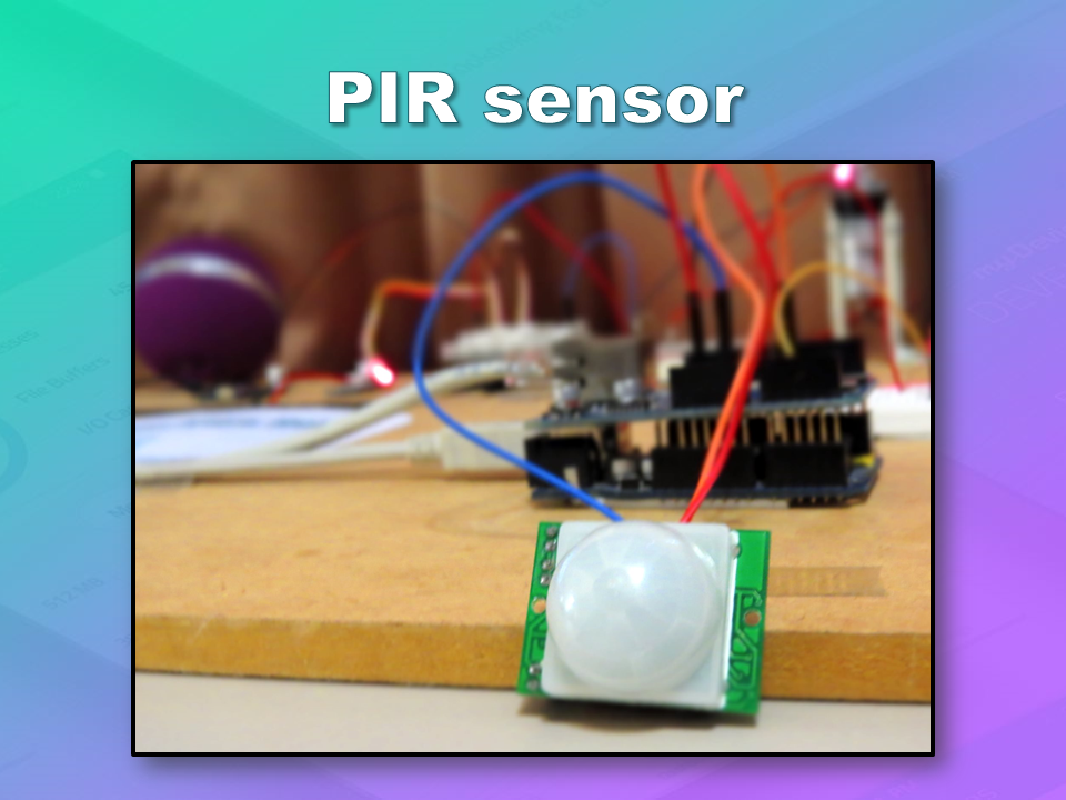
Arduino Ethernet - PIR Sensor
This sensor will be used to detect movement in the room. If a person walks into the room, this sensor will detect movement, and will trigger a message to be played on the Grove Serial MP3 player. The message will aim to get the person to identify themselves. They identify themselves by placing their RFID tag in close proximity to the Grove RFID reader. If the tag is valid, a "Welcome home" message is played on the Grove MP3 player. If a valid tag is not presented to the reader within 10 seconds, an Alarm will go off ("Alarm sound" played on Grove MP3 player.)
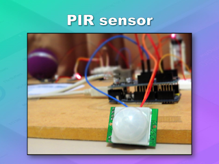
The PIR sensor is connected to digital Pin 6 of the Arduino, however, it is mapped to virtual pin 1 for better synchronisation with the Cayenne dashboard. This was done to capture ALL detections - as the PIR sensor could change from a LOW to HIGH and back to LOW state in between a Cayenne state check - and therefore, Cayenne could miss this motion detection.. Therefore we need to assign the PIR sensor to a virtual channel in the following way:
- Add New
- Device/Widget
- Sensors
- Motion
- Digital Motion Sensor - Motion Detector
- Widget Name: PIR sensor
- Select Device: Arduino Ethernet
- Connectivity: Virtual
- Pin: V1
- Choose Widget: 2-State Display
- Choose Icon: Light
- Step2: Add Sensor
- Select Settings from the PhotoResistor
- Choose Display: Value
- Save
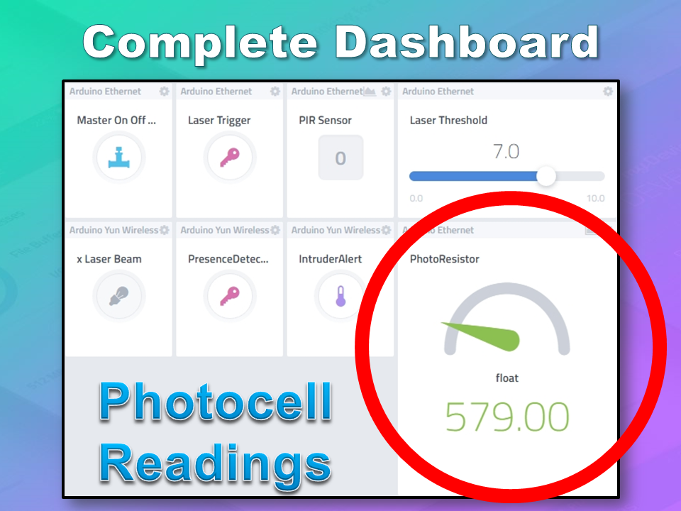
Arduino Ethernet - Photoresistor
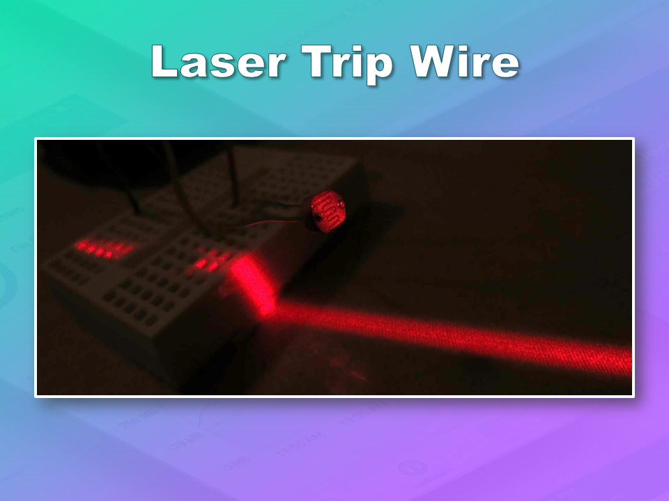
This sensor will be used with the laser beam to create a laser tripwire. If the sensor detects a change in light levels (drops below the threshold), it will activate the laser trigger button on the dashboard. The person will then be required to identify themselves etc etc (similar to the motion detection by the PIR sensor). The photoresistor widget will display the raw analog reading from the sensor (connected to A2), but is associated with virtual channel 2. I used a virtual channel for more control over this sensor. To add the Photoresistor to the dashboard:
- Add New
- Device/Widget
- Sensors
- Luminosity
- Photoresistor - Luminosity sensor
- Widget Name: PhotoResistor
- Select Device: Arduino Ethernet
- Connectivity: Virtual
- Pin: V2
- Choose Widget: Value
- Choose Icon: Light
- Step2: Add Sensor
Arduino Ethernet - Laser Trigger
The laser trigger is just an indicator that someone tripped the laser beam. The state of this widget is used to notify the Seeeduino that a presence has been detected. This widget is associated with virtual pin 4 on the Arduino UNO with Ethernet.
- Add New
- Device/Widget
- Actuators
- Generic
- Digital Output - Control a Digital Output
- Widget Name: Laser Trigger
- Select Device: Arduino Ethernet
- Connectivity: Virtual
- Pin: V4
- Choose Widget: Button
- Choose Icon: Lock
- Step2: Add Actuator
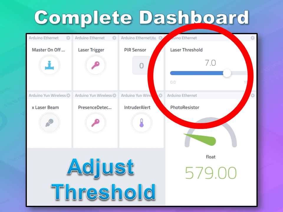
Arduino Ethernet - Laser Threshold
The laser threshold is used to manually configure the light level at which the laser trigger will trip. When the photoresistor value drops below the threshold value, the laser trigger icon will activate. This allows the threshold value to be updated from the Cayenne dashboard, rather than having to manually adjust the value in the Arduino code. Also, this threshold can be set remotely, in that you don't have to be near the Arduino to change this value. A very useful feature of this Security system. This widget is associated with virtual pin 5 on the Arduino UNO with Ethernet.
- Add New
- Device/Widget
- Actuators
- Generic
- PWM Output - Control a PWM Output
- Widget Name: Laser Threshold
- Select Device: Arduino Ethernet
- Connectivity: Virtual
- Pin: V5
- Choose Widget: Slider
- Slider Min Value: 0
- Slider Max Value: 10
- Step2: Add Actuator
The max value of the slider is 10 - due to a current bug in the Cayenne software. Once resolved, this value (as well as the relevant Arduino code) will need to be updated.
Seeeduino Cloud - Presence Detected
The presence detected widget is there to notify the Seeeduino Cloud that a presence has been detected on the Arduino Uno with Ethernet shield. When the PIR sensor detects movement or if the laser tripwire is tripped, Cayenne will change the state of the Presence Detected widget from LOW to HIGH. This is used within the Seeeduino Cloud to trigger the message "Place your keys on the Mat"
. If a valid RFID tag is read by the Grove RFID reader, then this widget's state will change back from HIGH to LOW, and the MasterSwitch will be deactivated - turning the Security system off. This widget is associated with Virtual pin 6 on the Seeeduino Cloud.
- Add New
- Device/Widget
- Actuators
- Generic
- Digital Output - Control a Digital Output
- Widget Name: Presence Detected
- Select Device: Seeeduino Cloud
- Connectivity: Virtual
- Pin: V6
- Choose Widget: Button
- Choose Icon: Lock
- Step2: Add Actuator
Seeeduino Cloud - Intruder Alert
If a valid RFID tag is not read by the Grove RFID reader within 10 seconds of a presence detection event, an alarm will sound, and this widget will be activated. This will trigger a notification event - to notify me of the unauthorised intrusion - via SMS or email. I will also have a visual indicator on the Cayenne dashboard that an intrusion has taken place. This widget is associated with Virtual pin 7 on the Seeeduino Cloud.
- Add New
- Device/Widget
- Actuators
- Generic
- Digital Output - Control a Digital Output
- Widget Name: Laser Trigger
- Select Device: Seeeduino Cloud
- Connectivity: Virtual
- Pin: V7
- Choose Widget: Button
- Choose Icon: Thermometer
- Step2: Add Actuator
Seeeduino Cloud - Laser Beam
The laser beam widget was created to allow for full control over the laser beam. The laser beam can be turned on or off from the Cayenne dashboard, and a connected to digital pin 7 on the Seeeduino Cloud.
- Add New
- Device/Widget
- Actuators
- Light
- Light Switch - Turn On/Off a Light
- Widget Name: xLaser Beam
- Select Device: Seeeduino Cloud
- Connectivity: Digital
- Pin: D7
- Choose Widget: Button
- Choose Icon: Light
- Step2: Add Actuator
Cayenne Triggers
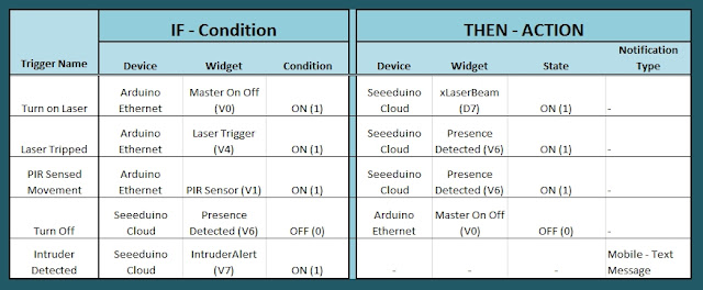
Now that all of the widgets have been added to the Dashboard, there is just one more step to complete the Security System. We need to setup the triggers. These triggers provide a level of automation that is easy to create within Cayenne, but would be very complicated otherwise. I set my triggers up as per the table below. Each row represents one of the triggers within my Cayenne dashboard. If you would like to see an example of how to add a trigger - please have a look at the video at the top of this tutorial.
Concluding comments
I used many different elements to put this home/office security project together - Multiple Arduinos were connected to the internet, both controlled by a web/smart phone app, cross-communication/synchronisation between the Arduinos, and the use of multiple sensors and modules including a laser beam !
This was way more than just a simple PIR sense and alarm project. I now have a personalised greeting and reminder system when I walk in the door. Everyone else has their own personalised greeting. I can enable my Security System remotely, from two blocks away, and if I wanted to - I could enable it from the other side of the world. I know instantly when someone has entered my house/office.... with an SMS alert straight to my phone.
This project could easily be extended:
- Press a button on my phone to manually trigger/play a specific message/sound/song
- Take a picture of the intruder
- Introduce fire or leak detection aswell
- Add other environmental sensors - Temperature / Humidity
- Connect it to lamp/light - creating a security light
I am sure you can think of more things I could do with this system. In fact, why don't you mention your ideas in the comments below.
Cayenne was instrumental in getting this project to work. I don't think I would know where to start if I had to do this project without this cool IoT platform. I think I will definitely be trying out a few more projects using Cayenne, and should you want to do the same, then please make sure to join Cayenne Beta:
Here is the link you need to get to the right place:
Cayenne Beta Link