Temperature lab, part 3: voltage divider
In Temperature lab, part2, I carefully measured the resistance vs. temperature curve for the Vishay BC Components NTCLE413E2103F520L thermistor, finding that either my thermometer was badly miscalibrated, or the manufacturer’s data sheet was misleading. I got a resistance of 9.7kΩ (not 10kΩ±1%) at 25° C and a B-value of 3174°K, not 3435°K±1%. A big part of the discrepancy is that I calibrated over a different temperature range, and the measured values deviated most from the manufacturer’s spec at low temperatures.
Actually, the manufacturer’s data sheet is not as bad as all that. They give specs for the ratio of the resistance at various temperatures to the resistance at 25° C, and their numbers do not fall along a simple curve. The report the B-value as a 2-point fit for T=25° C and T=85° C, but they also report resistance values every 5° C from –40° C to 105° C. One can compute the B-value for any pair:
But even if I use their calibration data down to 0° C, I don’t get as small a B-value as I get from my measurements. My calibration curve does not fit their spec, even if I look at the table, rather than the simple B-value model (though the table is closer to my measurements, it doesn’t match).
How big a difference would if make if I used their curve rather than mine? At R=6685Ω, we get the same temperature either way (96.446° F). At the resistance they claim for 0° C (27348Ω), their B-value model would give 33.90° F and mine would give 29.37° F. At the resistance I measured for 0° C (25.5kΩ), their model would give 36.67° F, while mine gives 32.32° F (which is closer than the measurement error I had on temperatures). So it looks like relying blindly on their B-value model introduces an error of over 4° F at low temperature, but in a digital thermometer for human body temperature, one would get nearly the same result with either calibration.
Voltage divider
The second part of the lab was to use the calibration curve to design a circuit to convert the resistance variation into a voltage variation that is nearly linear with temperature, at least over a small range. The simplest circuit to convert a resistance to a voltage is a voltage divider, which just requires a voltage source and another resistor.

A simple voltage divider for converting the thermistor resistance to a voltage. Because I want the output voltage to increase with temperature, but the resistance R(T) decreases with temperature, I put the thermistor on the top branch and fixed resistance on the lower branch.
Circuit drawn with the Circuit Lab editor.
The formula for the output voltage is simple: , where we are approximating
for temperature T in Kelvin. We’d like the voltage to be as linear as possible, which means we want the second derivative of Vout with respect to T to be zero. Obviously, we can’t do that for all values of T, but we might be able to do it for a particular value of T, and to have a small second derivative in that neighborhood.
We can take the derivatives by hand (or use a tool like Maple or Mathematica):
The second derivative is 0 if , that is if
.
We can use this formula to set the value for any temperature, for example, if we want linearity around 98.6° F (310.15° K), we can set the series resistor to 4323.64Ω.

Expected voltage curve using a voltage divider with series resistor optimized for 98.6° F. Note that the curve is fairly linear from about 70° F to about 130° F (where the red non-linear curve and the green linear approximation at 98.6° F are quite close.
Of course, commercially available resistors don’t come in values like 4323.64Ω, so in doing a design one has to pick an available resistor, using the EIA table of standard resistor values. A 4.7kΩ resistor looks pretty close, which would be color code yellow-violet-red. Too bad that I don’t have one. I do have a 5.1kΩ resistor, which would be optimal for linearizing at 90.06° F. We should, of course, ask students to do the resistor selection for a different temperature than the one we use in an example, and they should be using their own B-value.
Testing the voltage divider
I set up the voltage divider on a breadboard. Because I knew my wall wart had a huge ripple, I added a low-pass RC filter consisting of a 100Ω resistor and a 470µF electrolytic capacitor. This slightly complicates the analysis of the voltage output, since the Vdd voltage is itself dependent on a voltage divider.

Low-pass filter to clean up the output of the wall wart. With the low-pass filter in place, we can model the power supply as a 5.166V source and 100Ω series resistor.

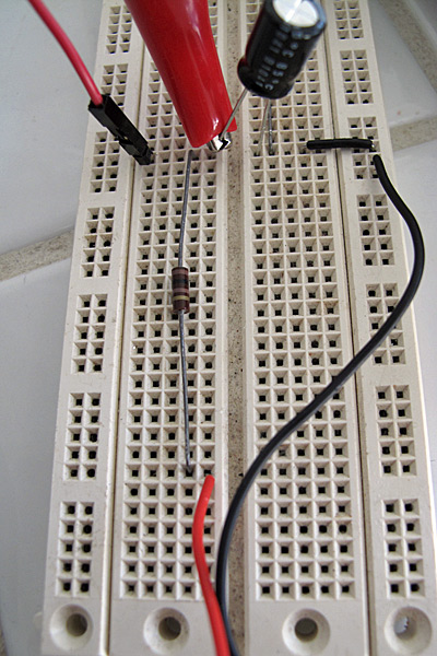
Here is what the low-pass filter looks like on the breadboard. The red and black wires from the bottom come from the connector to the wall wart. The 100Ω resistor runs vertically up the center, and the electrolytic capacitor connects across to the ground. The red clip lead is from the multimeter and is set up for measuring the voltage at the output of the filter.

Here is the full breadboard, showing the RC filter, the series resistor, the leads to the thermistor (the red and yellow lines with the crimp-on connectors), and the clip leads to the multimeter (the red and black alligator clips). I’ve found it very handy to have a number of double-sided header pins to make easy connection points on the breadboard for clip leads.

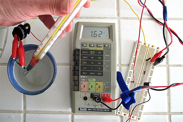
Here is the setup used for testing. The thermistor and thermometer are in the ceramic-cup water bath, with the thermometer held to keep the bulb in contact with the thermistor. You can see that the least-significant digit of the LCD display is a bit hard to read—applying some pressure to the display often makes it readable. Clip leads are essential to doing this experiment—holding the multimeter probes to test points would be a major hassle.
I only made 21 measurements of voltage, since I was not going to be fitting a model to the data, but just using the model I fit from the resistance measurements.

Plot of measured and theoretical voltage vs. temperature for the thermistor. The non-linear theoretical curve seems to be a pretty good fit (though it was not fit on this data, but on the previous series of resistance measurements).
The range of the voltages with the series resistor (from about 0.85v at freezing to 4.15v at boiling) is fairly reasonable for direct conversion to digital for the Arduino 10-bit ADC. In the middle of the range, the slope is about 0.0233 V/°F, which would give a resolution of about 0.2°F for Arduino readings. (Of course, with the Arduino, we would not need the low-pass filter, and Vdd would be a well-regulated 5v, so this calibration curve would have to be redone.) Even if we use the computational power of the Arduino to correct the non-linearity of the voltage curve, it is still useful to select the series resistor for the temperature we are most interested in, since that point gets the largest slope and hence the highest temperature resolution for fixed-size steps in voltage quantization.
Series-parallel
A lot of thermistor circuits on the web have a resistor in parallel with the thermistor, as well as the one in series. I wondered what the effect of this extra resistor was.
I tried analyzing this circuit also, using the same brute-force approach of computing the second derivative of the voltage and setting it to zero. I got a result that surprised me initially: the second derivative is zero if , where
is the resistance one would get for putting the series and parallel resistors in parallel. This is exactly the same condition as before, but with
replacing the series resistor
.
After I thought about this for a while, I realized that I should have been able to get there directly. If you think of the circuit as connecting the thermistor to a voltage divider consisting of R2 and R1, then you can replace the ground and that voltage divider by the Thévenin equivalent, which would be a voltage source with voltage and a series resistor consisting of R1 and R2 in parallel:
. The only reason to put in a parallel resistor would be to restrict the voltage range (which might be useful if the output were to be amplified, but is not useful if the output is going directly into an analog-to-digital converter whose full-scale range is 0 to Vdd).
Filed under: Circuits course Tagged: Arduino, bioengineering, circuits, course design, teaching, temperature measurement, Thévenin equivalent, thermistor, voltage divider


