Posts with «temperature» label

Captain Hermano’s Mystery Box is Full of Puzzles

[Raffi] needed a birthday present idea but he wanted to do something extra special. He realized that a big part of gift giving is the anticipation and excitement of opening the present. In order to prolong this experience, [Raffi] built an electronic puzzle box. The box contains the final gift, but first a series of puzzles must be solved in order to open the box.

The project runs on an Arduino Mega. This is hooked up to several sensors, including a temperature sensor, GPS unit, and CO sensor. There is also an LCD screen and numeric keypad for user input and output. The project page contains a flow chart that shows all of the puzzles and their solutions. One of the more interesting puzzles requires the user to blow tobacco smoke into a tube. The CO sensor detects the smoke and unlocks the next puzzle.

Some of the puzzles require interacting with outside systems. For example, one puzzle requires the user to send an email to the fictional Captain Hermano’s email address. If the correct keyword is included in the email, the user will receive a reply with the code to enter into the box. Another puzzle requires the user to call a particular phone number and listen for another riddle. We’ve included the video demonstration below.

This isn’t the first puzzle box we’ve seen, but each one has its own special flair. This one is very well made and looks like a lot of care was put into it. We’ve seen another that uses only discrete components. We’ve seen yet another that uses Morse code.

[Thanks Simon]


Filed under: Arduino Hacks
Hack a Day 28 Dec 18:01

Medical Tricorder Mark I

A handheld tricorder is as good a reason as any to start a project. The science-fiction-derived form factor provides an opportunity to work on a lot of different areas of hardware development like portable power, charging, communications between sensor and microcontroller. And of course you need a user interface so that the values being returned will have some meaning for the user.

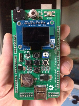
[Marcus B] has done a great job with all of this in his first version of a medical tricorder. The current design hosts two sensors, one measures skin temperature using infrared, the other is a pulse sensor.

For us it’s not the number of sensors that makes something a “tricorder” but the ability of the device to use those sensors to make a diagnosis (or to give the user enough hints to come to their own conclusion). [Marcus] shares similar views and with that in mind has designed in a real-time clock and an SD card slot. These can be used to log sensor data over time which may then be able to suggest ailments based on a known set of common diagnosis parameters.

Looking at the image above you may be wondering which chip is the microcontroller. This build is actually a shield for an Arduino hiding underneath.

There’s a demonstration video after the break. And if you find this impressive you won’t want to miss the Open Source Science Tricorder which is one of the finalists for the 2014 Hackaday Prize.


Filed under: Medical hacks
Hack a Day 08 Nov 03:01

End Table Kegerator Hides the Tap when You’re Not Looking

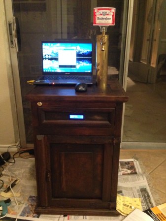
What’s better than an ordinary end table? How about an end table that can serve you beer? [Sam] had this exact idea and used his skills to make it a reality. The first step of the build was to acquire an end table that was big enough to hold all of the components for a functional kegerator. This proved to be a bit tricky, but [Sam] got lucky and scored a proper end table from a garage sale for only $5.00.

Next, [Sam] used bathroom sealant to seal up all of the cracks in the end table. This step is important to keep the inside cold. Good insulation will keep the beer colder, while using less electricity. Next, a hole was cut into the top of the table for the draft tower.

The draft tower is mounted to a couple of drawer slides. This allows the tower to raise up and down, keeping it out of sight when you don’t want it. The tower raises and lowers using a simple pulley system. A thin, high strength rope is attached to the tower. The other end is attached to a spool and a small motor. The motor can wind or unwind the spool in order to raise and lower the tower.

The table houses an Arduino, which controls the motor via a homemade H bridge. The Arduino is hooked up to a temperature sensor and a small LCD screen. This way, the users can see how cold their beer will be before they drink it.

To actually keep the beer cold, [Sam] ripped apart a mini fridge. He moved the compressor and condenser coils to the new table. He had to bend the coils to fit, taking care not to kink them. Finally he threw in the small keg, co2 tank and regulator. The final product is a livingroom gem that provides beer on demand.

Demo video (which is going the wrong way) can be found after the break.


Filed under: Arduino Hacks, Beer Hacks

Wireless Sensor Network for Temperature Sensing


This is an interesting implementation of Arduino and Wireless comunication. The user [priyansmurarka] posted:

Ok, so here is the basic problem statement. I need to develop a temperature sensing system such that the temperature from the sensor node is relayed to a co-ordinator sensor and then the co-ordinator node shows the user in a simple graphical form.

For the wireless communication, I used Xbee Series 2 modules with Arduino Board Shields.

Uses Melexis Temperature sensor and Arduino Board to monitor and plot ambient temperature.

The realization of this project is well documented on the [blog], with code, graphs and pictures.

Arduino Blog 25 Dec 17:45

Analog IR Temperature gauge


Introduction:
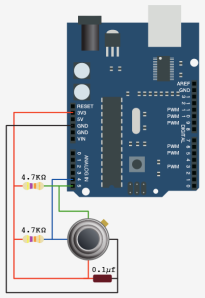
The IRTEMP module from Freetronics is an infrared remote temperature sensor that can be incorporated into your Arduino / microcontroller projects. It can scan a temperature between -33 to +220 C, and can be operated using a 3.3 to 5V power supply. It can be powered directly from the Arduino 5V pin.  This module can also provide an ambient temperature reading if required.
The Servo used in this project is a SG-5010 standard servo which will be utilised to display the temperature reading from the IRTEMP module.


Parts Required:
Freetronics Eleven or any compatible Arduino.
Freetronics IRTEMP module
MG-995  or SG-5010 Standard servo
Mini Breadboard 4.5cm x 3.5cm
Protoshieldand female header pins (not essential - but makes it more tidy)
9V Battery and Battery Clip
Wiresto connect it all together

Gauge parts:
Paper (to print the face of the gauge), and some glue to stick it to the wood.
MDF Standard panel (3mm width) - for the top and base of the gauge.
Galvanized bracket (25x25x40mm)
Timber screws: Hinge-long threads csk head Phillips drive (4G x 12mm)


The Video:


The Arduino Sketch:


     The above sketch was created using Fritzing.


Arduino Code:
You can download the Arduino IDE from this site.

The IRTemp gauge requires a driver library to be installed into the Arduino IDE.
The latest IRTemp driver library can be found here.

 1
2
3
4
5
6
7
8
9
10
11
12
13
14
15
16
17
18
19
20
21
22
23
24
25
26
27
28
29
30
31
32
33
34
35
36
37
38
39
40
41
42
43
44
45
46
47
48
49
50
51
52
53
54
55
56
57
58
59
60
61
62
63
64
65
66
67
68
69
70
71
72
73
74
75
76
77
78
79
80
81
82
83
84
/* -------------------------------------------------------
Analog IR Temperature Gauge: written by ScottC on 1st Dec 2012.
http://arduinobasics.blogspot.com/2012/12/arduino-basics-analog-ir-temperature.html


* Some of the code was adapted from a sketch by Andy Gelme (@geekscape)
* For more information on using the IRTEMP
see www.freetronics.com/irtemp

* IRTemp library uses an Arduino interrupt:
* If PIN_CLOCK = 2, then Arduino interrupt 0 is used
* If PIN_CLOCK = 3, then Arduino interrupt 1 is used
---------------------------------------------------------*/

#include "IRTemp.h"
#include <Servo.h>

Servo servo1;
static const byte PIN_DATA = 2;
static const byte PIN_CLOCK = 3; // Must be either pin 2 or pin 3
static const byte PIN_ACQUIRE = 4;

static const bool SCALE=false; // Celcius: false, Farenheit: true

/* Used to capture the temperature from the IRTEMP sensor */
float irTemperature;
int temp;

/* The minimum and maximum temperatures on the gauge. */
static const int minTemp = -45;
static const int maxTemp = 135;


/* The servo minimum and maximum angle rotation */
static const int minAngle = 0;
static const int maxAngle = 175;
int servoPos;

IRTemp irTemp(PIN_ACQUIRE, PIN_CLOCK, PIN_DATA);


/*----------------------SETUP----------------------*/

void setup(void) {

servo1.attach(9); // turn on servo
}


/*-----------------------LOOP-----------------------*/

void loop(void) {
irTemperature = irTemp.getIRTemperature(SCALE);
printTemperature("IR", irTemperature);

/* If you want the ambient temperature instead - then use the code below. */
//float ambientTemperature = irTemp.getAmbientTemperature(SCALE);
//printTemperature("Ambient", ambientTemperature);

}

/*-----------printTemperature function---------------*/

void printTemperature(char *type, float temperature) {

temp=(int) temperature;
servoPos = constrain(map(temp, minTemp,maxTemp,minAngle,maxAngle),minAngle,maxAngle);

if (isnan(temperature)) {
//is not a number, do nothing
}
else {

/* To test the minimum angle insert the code below */
//servoPos = minAngle;

/*To test the maximum angle, insert the code below */
//servoPos = maxAngle;

/* Rotate servo to the designated position */
servo1.write(servoPos);
}
}

The code above was formatted using hilite.me

Notes:
Ambient temperature: If you want to get the ambient temperature from the IRTEMP module, then have a look at lines 58-59.
Servo Angles: You will notice on line 36, the maximum servo angle used was 175. This value was obtained through trial and error (see below).

Calibrating the servo angles
You may need to calibrate your servo in order to move through an angle of 0 to 180 degrees without straining the motor.Change the minAngle on line 35to a safe value (for example: 10), and the maxAngle on line 36 to a value like 170. Remove the comment tag (//) on line 76, and then run the sketch. Lower the minAngle until it reaches the minimum value on the gauge, making sure that the servo doesn't sound like it is straining to keep it in position.

Add the comment tag (//) back in, and then take out the comment tag for line 79. And follow a similar process, until you reach the maximum value on the gauge. Once again, make sure that the servo is not making a straining noise to hold it at that value. Make sure to add the comment tag back in, when you have finished the calibration.

In this example, the servo's minAngle value was 0, and maxAngle value was 175 after calibration, however, as you can see from the video, the physical range of the servo turned out to be 0 to 180 degrees.


The Temperature Gauge Picture

The following gauge was created in Microsoft Excel using an X-Y chart.  Data labels were manually repositioned in order to get the desired numerical effect.


Inexpensive 6-channels temperature scanner

Did you ever look for a cheap temperature monitor capable of collecting up to six sensor readings?

Johnathan Hottell needed to monitor the engine temperature of his LB7 Duramax diesel truck to avoid over-heating problems in hot days. Looking for commercial products, he found several quite expensive scanners (around hundreds of dollars), so he decided to build its own monitor using an Arduino Pro Mini, six NTC thermistors and a Nokia 3310 LCD screen to display the temperature readings.

The result, which is described here in great details, cost around 40 $.

Via: DangerousPrototypes

Arduino Ambient Temperature Display

Larry Ogrodnek, creator of the LED NameTag kit, figured out a great way to use an RGB backlight LCD to display temperature data.

This is a really simple ambient display for temperature using an Arduino, an RGB backlight LCD, and a temperature sensor.

The LCD displays the temperature in Fahrenheit and Celsius and adjusts the color of the backlight depending on the reading. An ideal range is set at 61F to 67F. If the temperature is in this range the backlight will change green. Above this range and the color will change red, below the range it will change blue.

The great thing about these kinds of displays is that you can immediately get some rough information from across the room.

This is just a quick project. An obvious improvement is to have more variations in color depending on how far you are from your ideal range. I.e. as the temperature increases out of the ideal range, move along the color wheel and use shades of yellow, then orange before hitting red. There’s also a lot of empty room on that LCD. Possibly room for data from other sensors, or maybe just a larger (2-line) font.

This is perfect for someone like me who only needs 5 different temperature increments; really cold, cold, nice, hot, and really hot. Most of these parts and (Larry’s NameTag kit) are available in the Maker Shed.

[via Analog Machines]


Cryoscope gadget simulates tomorrow's weather today (video)

This multi-layered device can't shower you with hail or tan your outdoor-deprived complexion, regrettably. What it can do though, is deliver a direct haptic sensation of how warm or cold it'll be tomorrow, just in case you decide to venture out of your bedroom. An Arduino controller pulls in forecast data from the web and uses it to adjust a Peltier element and a cooling fan, which are housed along with a heat sink inside a neat and tactile aluminum box. The Cryoscope is the handiwork of industrial design student Robb Godshaw, and it's the reason he already knew he'd be wearing a skinny t-shirt and stripey socks in the video after the break.

Continue reading Cryoscope gadget simulates tomorrow's weather today (video)

Cryoscope gadget simulates tomorrow's weather today (video) originally appeared on Engadget on Mon, 06 Feb 2012 08:28:00 EST. Please see our terms for use of feeds.

Permalink | Email this | Comments