Halloween might be over, but for some of us there’s still another pumpkin-centric holiday right around the corner to give us an excuse to build projects out of various gourds. During a challenge at a local event, [Michael] came up with a virtual cornucopia of uses for all of the squashes he had on hand and built a touch-sensitive piano with all of them.
The musical instrument was dubbed the Harpsi-Gourd and makes extensive use of the Arduino touch-sensitive libraries. Beyond that, the project was constructed to be able to fit into a standard sized upright piano. While only 15 pumpkins are currently employed, the instrument can be scaled up to 48 pumpkins. Presumably they would need to be very small for the lid of the piano to still close.
The Harpsi-Gourd is a whimsical re-imagining of the original Makey Makey which can be used to do all kinds of things, including play Mario Bros. There are all kinds of other food-based musical instruments at your disposal as well, though.
In our eyes, there isn’t a much higher calling for Arduinos than using them to make musical instruments. [victorh88] has elevated them to rock star status with his homemade electronic drum kit.
The kit uses an Arduino Mega because of the number of inputs [victorh88] included. It’s not quite Neil Peart-level, but it does have a kick drum, a pair of rack toms, a floor tom, a snare, a crash, a ride, and a hi-hat. With the exception of the hi-hat, all the pieces in the kit use a piezo element to detect the hit and play the appropriate sample based on [Evan Kale]’s code, which was built to turn a Rock Band controller into a MIDI drum kit. The hi-hat uses an LDR embedded in a flip-flop to properly mimic the range of an actual acoustic hi-hat. This is a good idea that we have seen before.
[victorh88] made all the drums and pads out of MDF with four layers of pet screen sandwiched in between. In theory, this kit should be able to take anything he can throw at it, including YYZ. The crash and ride cymbals are MDF with a layer of EVA foam on top. This serves two purposes: it absorbs the shock from the sticks and mutes the sound of wood against wood. After that, it was just a matter of attaching everything to a standard e-drum frame using the existing interfaces. Watch [victorh88] beat a tattoo after the break.
There are a lot of unusual listings on eBay. If you’re wondering why someone would have a need for shredded cash, or a switchblade comb, or some “unicorn meat” (whatever that is), we’re honestly wondering the same thing. Sometimes, though, a listing that most people would consider bizarre finds its way to the workbench of someone with a little imagination. That was the case when [tinkartank] found three pipe organ pipes on eBay, bought them, and then built his own drivers.
The pipes have pitches of C, D, and F# (which make, as far we can tell, a C add9 flat5 no3 chord). [tinkartank] started by firing up the CNC machine and creating an enclosure to mount the pipes to. He added a church-like embellishment to the front window, and then started working on the controls for the pipes. Each pipe has its own fan, each salvaged from a hot air gun. The three are controlled with an Arduino. [tinkartank] notes that the fan noise is audible over the pipes, but there does seem to be an adequate amount of air going to each pipe.
This project is a good start towards a fully functional organ, provided [tinkartank] gets lucky enough to find the rest of the pipes from the organ. He’s already dreaming about building a full-sized organ of sorts, but in the meantime it might be interesting to use his existing pipes to build something from Myst.
Do any of you stay awake at night agonizing over how the keytar could get even cooler? The 80s are over, so we know none of us do. Yet here we are, [James Cochrane] has gone out and turned a HP ScanJet Keytar for no apparent reason other than he thought it’d be cool. Don’t bring the 80’s back [James], the world is still recovering from the last time.
Kidding aside (except for the part of not bringing the 80s back), the keytar build is simple, but pretty cool. [James] took an Arduino, a MIDI interface, and a stepper motor driver and integrated it into some of the scanner’s original features. The travel that used to run the optics back and forth now produce the sound; the case of the scanner provides the resonance. He uses a sensor to detect when he’s at the end of the scanner’s travel and it instantly reverses to avoid collision.
A off-the-shelf MIDI keyboard acts as the input for the instrument. As you can hear in the video after the break; it’s not the worst sounding instrument in this age of digital music. As a bonus, he has an additional tutorial on making any stepper motor a MIDI device at the end of the video.
If you don’t have an HP ScanJet lying around, but you are up to your ears in surplus Commodore 64s, we’ve got another build you should check out.
[Folkert van Heusden] sent us in his diabolical MIDI device. Ardio is a MIDI synthesizer of sorts, playing up to sixteen channels of square waves, each on its separate Arduino output pin, and mixed down to stereo with a bunch of resistors. It only plays square waves, and they don’t seem to be entirely in tune, but it makes a heck of a racket and makes use of an interesting architecture.
Ardio is made up of three separate el cheapo Arduino Minis, because…why not?! One Arduino handles the incoming MIDI data and sends note requests out to the other modules over I2C. The voice modules receive commands — play this frequency on that pin — and take care of the sound generation.
None of the chips are heavily loaded, and everything seems to run smoothly, despite the amount of data that’s coming in. As evidence, go download [Folkert]’s rendition of Abba’s classic “Chiquitita” in delicious sixteen-voice “harmony”. It’s a fun exercise in using what’s cheap and easy to get something done.
[dmitry] writes in to let us know about a new project that combines lasers with fans and turns the resulting modulation of the light beams into an autonomous soundscape. The piece is called “divider” and is a large, wall-mounted set of rails upon which seven red lasers are mounted on one end with seven matching light sensors mounted on the other end. Interrupting the lasers’ paths are forty-two brushless fans. Four Arduino Megas control the unit.
Laser beams shining into light sensors don’t do much of anything on their own, but when spinning fan blades interrupt each laser beam it modulates the solid beams and turns the readings of the sensors on the far end into a changing electrical signal which can be played as sound. Light being modulated by fan blades to create sound is the operating principle behind a Fan Synth, which we’ve discussed before as being a kind of siren (or you can go direct to that article’s fan synth demo video to hear what kind of sounds are possible from such a system.)
This project takes this entire concept of a fan synth further by not only increasing the number of lasers and fans, but by tying it all together into an autonomous system. The lasers are interrupted repeatedly and constantly, but never simultaneously. Listen to and watch it in action in the video below.
There isn’t a lot of in-depth technical information on the project page, but there are many really good photos. We especially love the way that the whole assembly is highly visual with the lasers turning on and off and interacting with different fans.
Any changing electrical signal can be played as sound, and if there’s one thing projects like self-playing musical hardware can teach us, it’s that if you have an electrical signal that looks strange or chaotic, hook a speaker up to it because it probably sounds pretty cool!
[gutbag] is a guitarist. And guitarists are notorious knob-twiddlers: they love their effects pedals. But when your music involves changing settings more than a few times in the middle of a song, it can get distracting. If only there were little robot hands that could turn the knobs (metaphorically, sorry) during the performance…
Tearing into his EHX Pitch Fork pedal, [gutbag] discovered that all of the external knob controls were being read by ADCs on the chip that did all of the processing. He replaced all of the controls with a DAC and some analog switches, coded up some MIDI logic in an ATmega328, and built himself a custom MIDI-controlled guitar pedal. Pretty slick, and he can now control it live with his iPad, or sequence the knobs with the rest of their MIDI system.
This wasn’t [gutbag]’s first foray into pedal automation, however. He’d previously automated a slew of his pedals that were already built to take control-voltage signals. What we like about this hack is the direct substitution of DAC for potentiometers. It’s just hackier. (Oh, and we’re envious of [gutbag]’s lab setup.)
This isn’t the first time we’ve covered [gutbag]’s band, Zaardvark, either. Way back in 2013, we featured an organ-pedal-to-MIDI hack of theirs. Keep on rockin’.
Give some mundane, old gear to an artist with a liking for technology, and he can turn it into a mesmerizing piece of art. [dmitry] created “red, an optic-sound electronic object” which uses simple light sources and optical elements to create an audio-visual performance installation. The project was the result of his collaboration with the Prometheus Special Design Bureau in Kazan, Russia. The inspiration for this project was Crystall, a reconstruction of an earlier project dating back to 1966. The idea behind “red” was to recreate the ideas and concepts from the 60’s ~ 80’s using modern solutions and materials.
The main part of the art installation consists of a ruby red crystal glass and a large piece of flexible Fresnel lens, positioned in front of a bright LED light source. The light source, the crystal and the Fresnel lens all move linearly, constantly changing the optical properties of the system. A pair of servos flexes and distorts the Fresnel lens while another one flips the crystal glass. A lot of recycled materials were used for the actuators – CD-ROM drive, an old scanner mechanism and old electric motors. Its got a Raspberry-Pi running Pure Data and Python scripts, with an Arduino connected to the sensors and actuators. The sensors define the position of various mechanical elements in relation to the range of their movement. There’s a couple of big speakers, which means there’s a beefy amplifier thrown in too. The sounds are correlated to the movement of the various elements, the intensity of the light and probably the color. There’s two mechanical paddle levers hanging in there, if you folks want to hazard some guesses on what they do.
The traditional theremin is more or less an audio oscillator with two metal rods. Using proximity sensing, one rod controls the pitch of the oscillator and the other controls the volume. [Teodor Costachiou] apparently asked himself the excellent question: Why does the proximity sensor have to use capacitance? The result is an Arduino-based theremin that uses IR sensors to determine hand position.
[Teodor] used a particular type of Arduino–the Flip and Click–because he wanted to use Click boards for the IR sensors and also to generate sound via an MP3 board based around a VS1053. The trick is that the VS1053 has a realtime MIDI mode, and that’s how this Theremin makes it tones.
Of course, a real theremin is distinctly analog. A tiny change in hand position creates a small change in the output. With digital sensors and sound generation, the output is more in discrete steps, but according to [Teodor], the effect isn’t bad. We were hoping for a video (or, at least, an audio clip) but [Teodor] pleaded that he’s not a musician. He did include a video of a real theremin performance with his post, and you can see it below. But that’s a real analog theremin.
If you want to build something more traditional, have a look at Open Theremin. Or, if you want to get your exercise, how about trying a terpsitone. If you do, and can play the theme to The Day the Earth Stood Still, we’d love to see the video. Meanwhile, if you didn’t know the theremin had an espionage connection, you haven’t been staying current on Hackaday posts.
Hackaday reader [Jan Ostman] has been making microcontroller-based DIY synthesizers for quite a while now. Recently, he’s opened up the source for a lot of them so that you can play along at home. All of these virtual-analog synths and soundmakers can be realized on an Arduino or AVR ATmega328 if you happen to have one lying around.
Extra parts like a keyboard, some pushbuttons, or some potentiometer knobs to twiddle won’t hurt if you’d like to make something more permanent or more obviously playable, like [Jan] does. On the other hand, if you’d just like to get your feet wet, I’ve tweaked his code to be more immediately plug-and-play. The code is straightforward enough that it’s a good learning platform. So let’s take a quick tour through three drum machines and a string synth, each of which you can build on a breadboard in just a few minutes.
To install on an Arduino UNO, fetch the zip file from this GitHub repository, and move each subfolder to your Arduino sketch directory. You’re ready to play along.
Simple Drum Machines
[Jan] has two sample-playback~based drum machines that he’s published the code for: the dsp-D8 with straight-ahead drum samples and the dsp-L8 loaded with Latin percussion. They’re essentially the same code base, but with different samples, so we’ll treat them together.
Working through [Jan]’s code inspired me to write up a longer article on DDS playback, so if you want to brush up on the fundamentals, you can head over there. The short version is that you can change the pitch of playback of a sample by using a counter that’s much larger than the number of data points you’re going to play.
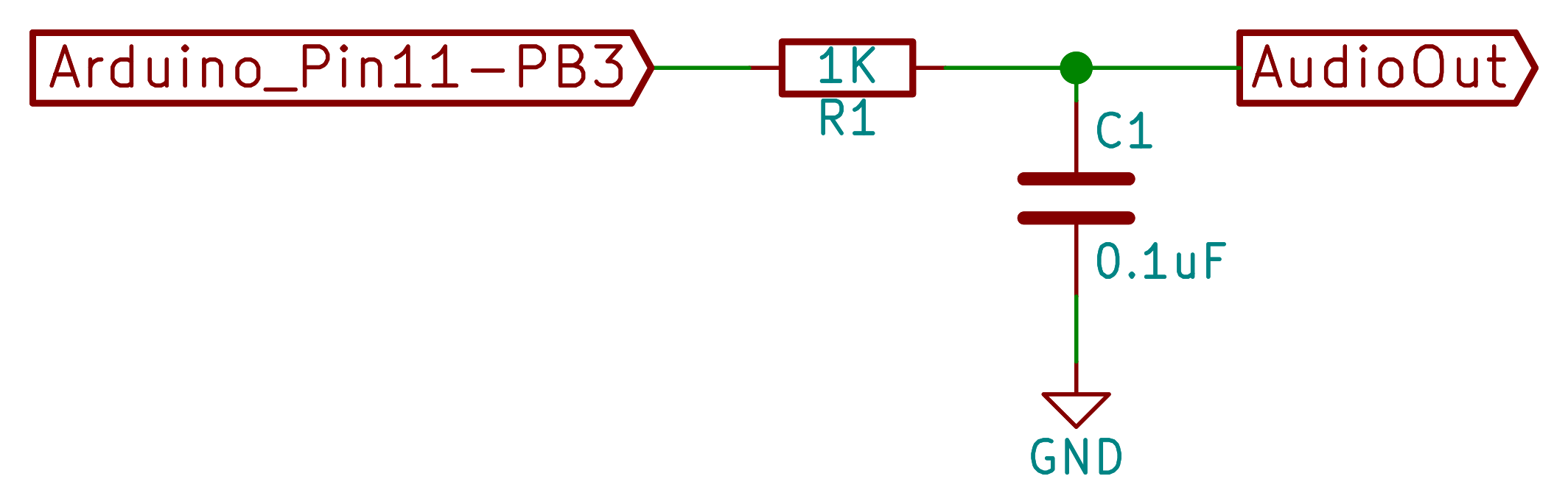
[Jan]’s drum machines all use the AVR’s hardware pulse-width modulation (PWM) peripherals to play the samples back out. You could use something fancier, but this gets the job done with just an optional resistor and capacitor filter on the output, bringing the total parts count to three: Arduino, 1 KOhm resistor, and a decent-sized (0.1 uF?) capacitor. An interrupt service routine (ISR) periodically loads a new sample value into the PWM register, and the AVR’s peripheral hardware takes care of the rest.
One nice touch is the use of a circular buffer that holds the playback sample values until the ISR is ready for them. In the case of the drum machines, there’s not much math for the CPU to do — it just combines the samples from all of the different simultaneous voices — but in his more complicated modules this buffer allows the CPU to occasionally take more time to calculate a sample value than it would otherwise have between updates. It buys [Jan]’s code some breathing room and still allows it to make the sample-playback schedule without glitching.
[Jan] adds individual pitch control for each sample, which is great for live playing or tweaking, and you can watch him use them in his two videos: one for the dsp-D8 and another for the dsp-L8. Wiring up so many knobs is a breadboard-salad, though, so I’ve gone through the code for you with a fine-toothed chainsaw, and hacked off [Jan]’s button-and-knob interface and replaced it with the Arduino’s built-in serial I/O.
To play my version of [Jan]’s drum machines, each sample is mapped to a key in the home row: “asdfjkl;”. If you’ve got a proper serial terminal program that transmits each keystroke in real-time, you’ll be tapping out rhythms at 9600 baud in no time. Note that the Arduino IDE’s built-in terminal only sends the keystroke after you hit “enter” — this makes playing in tempo very difficult. (I use screen /dev/ttyACM0 9600 or the terminal that’s built-in with Python’s pyserial library myself. What do Windows folks use for a real-time terminal?)
If you haven’t already, download this zip file, move each sub-folder to your Arduino sketch directory, and connect an amplified speaker either directly to your Arduino’s pin 11 and ground, or include an RC filter. It’ll only take a second before you’re playing. When you want the full version with all the knobs, head on over to [Jan]’s site.
O2 Minipops
[Jan]’s O2 Minipops machine mimics an old-school rhythm box: the Korg mini pops 7. Whether this primitive drum machine is horribly cheesy or divinely kitschy is in the ear of the beholder, but it’s a classic that has been used all over. [Jan]’s named his after an epic album Oxygene by Jean-Michel Jarre. You’ll hear them starting around 1:40 into the clip. Jarre famously used to press multiple buttons on the Minipops, making more complex drum patterns by playing more than one at a time.
The nice thing about having your own Minipops in firmware is that you can add the features you want to it. Instead of having to mash down multiple plastic buttons live on stage like poor Mr. Jarre, you can just tweak the firmware to suit. Need longer patterns? You’ve got the RAM. Emphasis? Swing? Tap tempo? It’s all just a matter of a few lines of code.
The sound playback code is just like the simpler drum machines above, so we won’t have to cover that again. The only real addition is the sequencer, but that’s where the real magic lies. After all, what’s a drum machine without some beats? Because there are eight possible drum sounds, each beat is a byte and so four bars of 4/4 time is just sixteen bytes stored in memory. I broke the data out into its own header file O2_data.h, so have a look there for the pre-programmed rhythms, and feel free to modify them to suit your own needs.
In order to make the O2 Minipops immediately playable, I stripped out the potentiometer code again (sorry [Jan]!) and passed off control over the serial port. The “user interface” has five controls. Press j and k to switch between patterns and f and d to speed up or slow down. (They’re under your first two fingers in the home row.) The space bar starts and stops the drum machine.
Try switching between the patterns on the fly with j and k — it’s a surprisingly fun way to create your own, slightly less cheesy, patterns. You need to download this code and give it a try. Trust me.
[Jan]’s Solina is a “virtual analog” in the sense that it builds up sawtooth waveforms in the microcontroller’s RAM and then outputs the corresponding voltage through PWM. And that’s a good start for a string synthesizer, because a filtered sawtooth waveform is a good first stab at the sound put out by a violin, for example.
Solina — the clone
The secret to the sound of the string section of an orchestra (and to string synthesizers that mimic it) is that it’s a combination of many different bowed instruments all playing at once. No matter how precise the players, they’re each slightly differently tuned, and none of the strings are resonating exactly in phase. The Solina mimics this by detuning each oscillator, naturally, and by moving them in and out of phase with each other. If you want to dig into the details of how exactly [Jan]’s Solina works, he explains it well in this blog post.
Again, I’ve converted it for direct-serial control, and you can control the envelope, detune, LFO speed, and modulation depth over the serial port. Press the spacebar once to simulate a keypress, and again to let go. Try the Solina with detune and pitch modulation around twenty, and play with the LFO rate and other parameters. That’s a lot of useful noise for just some sawtooth waves.
Keyboards and What’s Next
[Jan]’s builds are much more than what we’re demonstrating here, of course. His blog kicks off (in 2009!) with a project that essentially shoe-horns a PC into a keyboard enclosure, and the Solina and others get their own keys too. We’ve just presented the kernel of any such project — there’s a lot of labor-of-love left in wiring up all of the diodes necessary to do detection on a keyboard matrix, to say nothing of building enclosures, wiring up potentiometers, and making nice-looking front panels. But if you want to start down that path, you’ve at least got a good start.
[Jan]’s current project is the Minimo miniature monophonic synth that takes the Solina a step further and adds a lowpass filter with (digital) resonance to it. The resulting sounds are great, so we’re excited to see where [Jan] takes this one in the future.
Thanks again, [Jan], for opening the code up. And if any of you build something with this, be sure to post in the comments and let us all know. Since I started playing around with these, I’ve got the hankering to modularize the code up a bit and make it into something that’s even easier to adapt and modify. Maybe we’ll have to start up a Hackaday.io project — these little simple synths are just too much fun!