We got a question from [DC Darsen], who apparently has a broken electronic organ from the mid-70s that needs a new top-octave generator. A top-octave generator is essentially an IC with twelve or thirteen logic counters or dividers on-board that produces an octave’s worth of notes for the cheesy organ in question, and then a string of divide-by-two logic counters divide these down to cover the rest of the keyboard. With the sound board making every pitch all the time, the keyboard is just a simple set of switches that let the sound through or not. Easy-peasy, as long as you have a working TOG.
I bravely, and/or naïvely, said that I could whip one up on an AVR-based Arduino, tried, and failed. The timing requirements were just too tight for the obvious approach, so I turned it over to the Hackaday community because I had this nagging feeling that surely someone could rise to the challenge.
The community delivered! Or, particularly, [Ag Prismatic]. With a clever approach to the problem, some assembly language programming, and an optional Arduino crystalectomy, [AP]’s solution is rock-solid and glitch-free, and you could build one right now if you wanted to. We expect a proliferation of cheesy synth sounds will result. This is some tight code. Hat tip!
Squeezing Cycles Out of a Microcontroller
Let’s take a look at [AP]’s code. The approach that [AP] used is tremendously useful whenever you have a microcontroller that has to do many things at once, on a rigid schedule, and there’s not enough CPU time between the smallest time increments to do much. Maybe you’d like to control twelve servo motors with no glitching? Or drive many LEDs with binary code modulation instead of primitive pulse-width modulation? Then you’re going to want to read on.
There are two additional tricks that [AP] uses: one to fake cycles with a non-integer number of counts, and one to make the AVR’s ISR timing absolutely jitter-free. Finally, [Ag] ended up writing everything in AVR assembly language to make the timing work out, but was nice enough to also include a C listing. So if you’d like to get your feet wet with assembly, this is a good start.
In short, if you’re doing anything with hard timing requirements on limited microcontroller resources, especially an AVR, read on!
Taking Time to Think

The goal of the top-octave generator is to take an input clock and divide it down into twelve simultaneous sub-clocks that all run independently of each other. Just to be clear, this means updating between zero and twelve GPIO pins at a frequency of 1 MHz or so — updating every twenty clock cycles at the AVR’s maximum CPU speed. If you thought you could loop through twelve counters and decide which pins to flip in twenty cycles, you’d be mistaken.
But recognizing the problem is the first step to solving it. Although the tightest schedule might require flipping one pin exactly twenty clocks after flipping another, most of the time there are more cycles between pin updates — hundreds up to a few thousand. So the solution is to recognize when there is time to think, and use this time to pre-calculate a buffer full of next states.
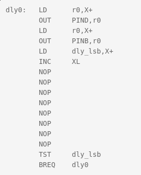
 [Ag]’s solution uses a few different loops that run exactly 20, 40, and 60 cycles each — the longer versions being just the 20-cycle one padded out with
 NOPs. These loops run inside an interrupt-service routine (ISR). When there are 80 or more cycles of thinking time until the next scheduled pin change, control is returned to the main loop and the next interrupt is set to re-enter the tight loops at the next necessary update time.
All the fast loop has to do is read two bytes, write them out to the GPIO pins, increment the pointer to the next row of data, and figure out if it needs to stall for 20 or 40 additional cycles, or set the ISR timer for longer delays and return to calculations. And this it can do in just twelve of the twenty cycles! Slick.
Buffers
Taking a step back from the particulars of the top-octave generator, this is a classic problem and a classic solution. It’s worth your time to internalize it, because you’ll run into this situation any time you have real-time constraints. The problem is that on average there’s more than enough time to complete the calculations, but that in the worst cases it’s impossible. So you split the problem in two parts: one that runs as fast as possible, and one that does the calculations that the fast section will need. And connecting together fast and slow processes is exactly why computer science gave us the buffer.
In [AP]’s code, this buffer is a table where each entry has two bytes for the state of the twelve GPIO pins, and one byte to store the number of clock cycles to delay until the next update. One other byte is left empty, yielding 64 entries or 256 bytes for the whole table. Why 256 bytes? Because the AVR has an 8-bit unsigned integer, wrapping around from the end of the table back to the beginning is automatic, saving a few cycles of wasteful if statements.
But even with this fast/slow division of labor, there is not much time left over for doing the pre-calculation. Sounding the highest C on a piano keyboard (4186 Hz) with a 20 MHz CPU clock requires toggling a GPIO pin every 2,390 cycles, so that’s the most time that the CPU will ever see. When the virtual oscillators are out of phase, this can be a lot shorter. By running the AVR at its full 20 MHz, and coding everything in assembly, [AP] can run the calculations fast enough to support twelve oscillators. At 16 MHz, there’s only time for ten, so every small optimization counts.
Some Optimization Required
Perhaps one of the cleverest optimizations that [AP] made is the one that makes this possible at all. The original top-octave chips divide down a 2 MHz square wave by a set of carefully chosen integer divisors. Running the AVR equivalent at 2 MHz resolution would mean just ten clocks per update and [AP]’s fast routine needed twelve, so the update rate would have to be halved. But that means that some odd divisors on the original IC would end up non-integral in the AVR code. For example, the highest C is reproduced in silicon as 2 MHz / 239, so to pull this off at 1 MHz requires counting up to 119.5 on an integer CPU. How to cope?
You could imagine counting to 119 half of the time, and 120 the other. Nobody will notice the tiny difference in duty cycle, and the pitch will still be spot on. The C programmer in me would want to code something like this:
uint8_t counter[12] = { 0, ... };
uint8_t counter_top[12] = { 119, ... };
uint8_t is_counter_fractional[12] = { 1, 0, ... };
uint8_t is_low_this_time[12] = { 0, ... };

// and then loop
for ( i=0 ; i<12; ++i){
  if ( counter[i] == 0 ){
    if ( is_counter_fractional[i] ){
      if ( is_low_this_time[i] ){
        counter[i] = counter_top[i];
    is_low_this_time = 0;
      else {
        counter[i] = counter_top[i] + 1;
    is_low_this_time = 1;
      }
    }
  }
}
That will work, but the ifs costs evaluation time. Instead, [AP] did the equivalent of this:
uint8_t counter[12] = { 0, ... };
uint8_t counter_top[12] = { 119, ... };
uint8_t phase[12] = { 1, 0, ... };

for ( i=0 ; i<12; ++i){
  if ( counter[i] == 0 ){
    counter[i] = counter_top[i] + phase[i];
    counter_top[i] = counter[i];
    phase[i] = -phase[i];
  }
}
What’s particularly clever about this construction is that it doesn’t need to distinguish between the integer and non-integer delays in code. Alternately adding and subtracting one from the non-integer values gets us around the “half” problem, while setting the phase variable to 0 means that the integer-valued divisors run unmodified, with no ifs.
The final optimization shows just how far [AP] went to make this AVR top-octave generator work like the real IC. When setting the timer to re-enter the fast loop in the ISR, there’s the possibility for one cycle’s worth of jitter. Because AVR instructions run in either one or two clock cycles, it’s possible that a two-cycle instruction could be running when the ISR timer comes due. Depending on luck, then, the interrupt will run four or five clocks later: see the section “Interrupt Response Time” in the AVR data sheet for details.
In a prologue to the ISR, [AP]’s code double-checks the hardware timer to see if it has entered on a one-cycle instruction, and adds in an extra NOP to compensate. This makes the resulting oscillator nearly jitter free, pushing out a possible source of 50 ns (one cycle at 20 MHz) slop. I don’t think you’d be able to hear this jitter, but the result surely looks pretty on the oscilloscope, and this might be a useful trick to know if you’re ever doing ultra-precise timing with ISRs.
The Proof of the Pudding
Naturally, I had to test out this code on real hardware. The first step was to pull a random Arduino-clone out of the closet and flash it in. Because “Arduinos” run at 16 MHz with the stock crystal, the result is that a nominal 440 Hz concert A plays more like a slightly sharp F, a musical third down. It sounds fine on its own, but you won’t be able to play along with any other instruments that are tuned to 440 Hz.
[AP]’s preferred solution is to run the AVR chip at 20 MHz. Since the hardware requirements are very modest, you could use a $0.50 ATTiny816 coupled with a 20 MHz crystal and you’d have a top-octave generator for literal pocket change — certainly cheaper than buying even an Arduino clone. I tested it out with an ATMega48P and a 20 MHz crystal on a breadboard because it’s what I had. Or you could perform crystalectomy on your Arduino to get it running at full speed.
We went back and forth via e-mail about all the other (firmware) options. [AP] had tried them all. You could trim the ISR down to 16 cycles and run at 16 MHz, but then there’s only enough CPU time in the main loop to support ten notes, two shy of a full octave. You could try other update rates than 1 MHz, but the divisors end up being pretty wonky. To quote [AP] from our e-mail discussion on the topic:
“After playing with the divider values from the original top octave generator IC and trying different base frequencies, it appears that the 2 MHz update rate is a “sweet spot” for getting reasonable integer divisors with < +/-2 cents of error. The original designers of the chip must have done the same calculations.”
To make a full organ out of this setup, you’ll also need twelve binary counter chips to divide down each note to fill up the lower registers of the keyboard, but these are easy to design with and cost only a few tens of cents apiece. All in all, thanks to [AP]’s extremely clever coding, you can build a fully-polyphonic noisemaker that spits out 96 simultaneous pitches, all in tune, for under $10. That’s pretty amazing.
And of course, I’ve already built a small device based on this code, but that’s a topic for another post. To be continued.


