New Project: Color Recognition Lock
 How to make an basic electronic color sensor and how to use it to make a color activated lock box

 How to make an basic electronic color sensor and how to use it to make a color activated lock box

If you have ever forgotten your computer password after a long weekend or maybe you can remember it but just can’t seem to type it correctly, [Thomas] has a project for you. It’s a physical key that locks and unlocks your PC.
So how does it work? The heart of the project is an Arduino Leonardo. You may recall that this board is a bit different from the preceding Arduinos as it can enumerate on a host computer as a Human Interface Device (HID), such as a keyboard or mouse. The Arduino sketch continually reads an input pin using an internal pull-up resistor to make it logic high with the key switch connecting the signal to ground. When the Arduino sees the pin change from high to low, it sends out a keyboard command consisting of the Windows Key and “L”, which is the keyboard shortcut for locking the computer.
When the physical key is turned again, the Arduino sees the pin change back to a high state and it again emulates a keyboard but this time enters your password. You do have to include your password in the Arduino sketch for this to work. In addition, there are two LED’s wired up to show if the computer is locked or not, but you’ll be able to tell pretty quick when trying to get back to work.
The Arduino sketch and Frtitzing diagram are available at the above link in case you would like to make one yourself.


Learn how to use various numeric keypads with your Arduino.
This is chapter forty-two of our huge Arduino tutorial series. Updated 16/12/2013
Numeric keypads can provide a simple end-user alternative for various interfaces for your projects. Or if you need a lot of buttons, they can save you a lot of time with regards to construction. We’ll run through connecting them, using the Arduino library and then finish with a useful example sketch.
Getting Started
Numeric keypads are available from many retailers, and no matter where you get them from, make sure you can get the data sheet, as this will make life easier when wiring them up. Here are the two examples for our tutorial, from Futurlec (slow and cheap):

Again, the data sheet is important as it will tell you which pins or connectors on the keypad are for the rows and columns, for example the black keypad shown above. If you don’t have the data sheet – you will need to manually determine which contacts are for the rows and columns.
This can be done using the continuity function of a multimeter (the buzzer). Start by placing one probe on pin 1, the other probe on pin 2, and press the keys one by one. Make a note of when a button completes the circuit, then move onto the next pin. Soon you will know which is which. For example, on the example keypad pins 1 and 5 are for button “1″, 2 and 5 for “4″, etc…
Furthermore some keypads will have the pins soldered to the end, some will not. With our two example keypads, the smaller unit had the pins – and we soldered pins to the large white unit:

At this point please download and install the keypad Arduino library. Now we’ll demonstrate how to use both keypads in simple examples.
Using a 12 digit keypad
We’ll use the small black keypad from Futurlec, an Arduino Uno-compatible and an LCD with an I2C interface for display purposes. If you don’t have an LCD you could always send the text to the serial monitor instead.
If your keypad is different to ours, take note of the lines in the sketch from:
// keypad type definition
As you need to change the numbers in the arrays rowPins[ROWS] and colPins[COLS]. You enter the digital pin numbers connected to the rows and columns of the keypad respectively.
Furthermore, the array keys stores the values displayed in the LCD when a particular button is pressed. You can see we’ve matched it with the physical keypad used, however you can change it to whatever you need. But for now, enter and upload the following sketch once you’re satisfied with the row/pin number allocations:
/* Numeric keypad and I2C LCD
   https://tronixstuff.com/tutorials > chapter 42
   Uses Keypad library for Arduino
   http://www.arduino.cc/playground/Code/Keypad
   by Mark Stanley, Alexander Brevig */

#include "Keypad.h"
#include "Wire.h" // for I2C LCD
#include "LiquidCrystal_I2C.h" // for I2C bus LCD module
// http://www.dfrobot.com/wiki/index.php/I2C/TWI_LCD1602_Module_(SKU:_DFR0063)
LiquidCrystal_I2C lcd(0x27,16,2);  // set the LCD address to 0x27 for a 16 chars and 2 line display

// keypad type definition
const byte ROWS = 4; //four rows
const byte COLS = 3; //three columns
char keys[ROWS][COLS] =
 {{'1','2','3'},
  {'4','5','6'},
  {'7','8','9'},
  {'*','0','#'}};

byte rowPins[ROWS] = {
  5, 4, 3, 2}; //connect to the row pinouts of the keypad
byte colPins[COLS] = {
  8, 7, 6}; // connect to the column pinouts of the keypad

int count=0;

Keypad keypad = Keypad( makeKeymap(keys), rowPins, colPins, ROWS, COLS );

void setup()
{
  lcd.init();          // initialize the lcd
  lcd.backlight(); // turn on LCD backlight
}

void loop()
{
  char key = keypad.getKey();
  if (key != NO_KEY)
  {
    lcd.print(key);
    count++;
    if (count==17)
    {
      lcd.clear();
      count=0;
    }
  }
}
And the results of the sketch are shown in this video.
So now you can see how the button presses can be translated into data for use in a sketch. We’ll now repeat this demonstration with the larger keypad.
Using a 16 digit keypad
We’ll use the larger white 4×4 keypad from Futurlec, an Arduino Uno-compatible and for a change the I2C LCD from Akafugu for display purposes. (We reviewed these previously). Again, if you don’t have an LCD you could always send the text to the serial monitor instead. Wire up the LCD and then connect the keypad to the Arduino in the following manner:
/* Numeric keypad and I2C LCD
   https://tronixstuff.com/tutorials > chapter 42
   Uses Keypad library for Arduino
   http://www.arduino.cc/playground/Code/Keypad
   by Mark Stanley, Alexander Brevig */

#include "Keypad.h"
#include "Wire.h" // for I2C LCD
#include "TWILiquidCrystal.h"
// http://store.akafugu.jp/products/26
LiquidCrystal lcd(12, 11, 5, 4, 3, 2);

const byte ROWS = 4; //four rows
const byte COLS = 4; //four columns
char keys[ROWS][COLS] =
 {{'1','2','3','A'},
  {'4','5','6','B'},
  {'7','8','9','C'},
  {'*','0','#','D'}};
byte rowPins[ROWS] = {
  5, 4, 3, 2}; //connect to the row pinouts of the keypad
byte colPins[COLS] = {
  9, 8, 7, 6}; //connect to the column pinouts of the keypad
int count=0;

Keypad keypad = Keypad( makeKeymap(keys), rowPins, colPins, ROWS, COLS );

void setup()
{
  Serial.begin(9600);
  lcd.begin(16, 2);
  lcd.print("Keypad test!");
  delay(1000);
  lcd.clear();
}

void loop()
{
  char key = keypad.getKey();
  if (key != NO_KEY)
  {
    lcd.print(key);
    Serial.print(key);
    count++;
    if (count==17)
    {
      lcd.clear();
      count=0;
    }
  }
}
And again you can see the results of the sketch above in this video.
And now for an example project, one which is probably the most requested use of the numeric keypad…
Example Project – PIN access system
The most-requested use for a numeric keypad seems to be a “PIN” style application, where the Arduino is instructed to do something based on a correct number being entered into the keypad. The following sketch uses the hardware described for the previous sketch and implements a six-digit PIN entry system. The actions to take place can be inserted in the functions correctPIN() and incorrectPIN(). And the PIN is set in the array char PIN[6]. With a little extra work you could create your own PIN-change function as well.
// PIN switch with 16-digit numeric keypad
// https://tronixstuff.com/tutorials > chapter 42

#include "Keypad.h"
#include <Wire.h>
#include <TWILiquidCrystal.h>
LiquidCrystal lcd(12, 11, 5, 4, 3, 2);

const byte ROWS = 4; //four rows
const byte COLS = 4; //four columns
char keys[ROWS][COLS] =
{
  {
    '1','2','3','A'  }
  ,
  {
    '4','5','6','B'  }
  ,
  {
    '7','8','9','C'  }
  ,
  {
    '*','0','#','D'  }
};
byte rowPins[ROWS] = {
  5, 4, 3, 2}; //connect to the row pinouts of the keypad
byte colPins[COLS] = {
  9, 8, 7, 6}; //connect to the column pinouts of the keypad

Keypad keypad = Keypad( makeKeymap(keys), rowPins, colPins, ROWS, COLS );

char PIN[6]={
  '1','2','A','D','5','6'}; // our secret (!) number
char attempt[6]={
  '0','0','0','0','0','0'}; // used for comparison
int z=0;

void setup()
{
  Serial.begin(9600);
  lcd.begin(16, 2);
  lcd.print("PIN Lock ");
  delay(1000);
  lcd.clear();
  lcd.print("  Enter PIN...");
}

void correctPIN() // do this if correct PIN entered
{
  lcd.print("* Correct PIN *");
  delay(1000);
  lcd.clear();
  lcd.print("  Enter PIN...");
}

void incorrectPIN() // do this if incorrect PIN entered
{
  lcd.print(" * Try again *");
  delay(1000);
  lcd.clear();
  lcd.print("  Enter PIN...");
}

void checkPIN()
{
  int correct=0;
  int i;
  for ( i = 0;   i < 6 ;  i++ )
  {

    if (attempt[i]==PIN[i])
    {
      correct++;
    }
  }
  if (correct==6)
  {
    correctPIN();
  }
  else
  {
    incorrectPIN();
  }

  for (int zz=0; zz<6; zz++)
  {
    attempt[zz]='0';
  }
}

void readKeypad()
{
  char key = keypad.getKey();
  if (key != NO_KEY)
  {
    attempt[z]=key;
    z++;
    switch(key)
    {
    case '*':
      z=0;
      break;
    case '#':
      z=0;
      delay(100); // for extra debounce
      lcd.clear();
      checkPIN();
      break;
    }
  }
}

void loop()
{
  readKeypad();
}
The project is demonstrated in this video.
Conclusion
So now you have the ability to use twelve and sixteen-button keypads with your Arduino systems. I’m sure you will come up with something useful and interesting using the keypads in the near future.

Stay tuned for upcoming Arduino tutorials by subscribing to the blog, RSS feed (top-right), twitter or joining our Google Group. And if you enjoyed the tutorial, or want to introduce someone else to the interesting world of Arduino – check out my book (now in a third printing!) “Arduino Workshop” from No Starch Press.
Learn how to use various numeric keypads with your Arduino.
This is chapter forty-two of our huge Arduino tutorial series. Updated 16/12/2013
Numeric keypads can provide a simple end-user alternative for various interfaces for your projects. Or if you need a lot of buttons, they can save you a lot of time with regards to construction. We’ll run through connecting them, using the Arduino library and then finish with a useful example sketch.
Getting Started
Numeric keypads are available from many retailers, and no matter where you get them from, make sure you can get the data sheet, as this will make life easier when wiring them up. Here are the two examples for our tutorial, from Futurlec (slow and cheap):

Again, the data sheet is important as it will tell you which pins or connectors on the keypad are for the rows and columns, for example the black keypad shown above. If you don’t have the data sheet – you will need to manually determine which contacts are for the rows and columns.
This can be done using the continuity function of a multimeter (the buzzer). Start by placing one probe on pin 1, the other probe on pin 2, and press the keys one by one. Make a note of when a button completes the circuit, then move onto the next pin. Soon you will know which is which. For example, on the example keypad pins 1 and 5 are for button “1″, 2 and 5 for “4″, etc…
Furthermore some keypads will have the pins soldered to the end, some will not. With our two example keypads, the smaller unit had the pins – and we soldered pins to the large white unit:

At this point please download and install the keypad Arduino library. Now we’ll demonstrate how to use both keypads in simple examples.
Using a 12 digit keypad
We’ll use the small black keypad from Futurlec, an Arduino Uno-compatible and an LCD with an I2C interface for display purposes. If you don’t have an LCD you could always send the text to the serial monitor instead.
If your keypad is different to ours, take note of the lines in the sketch from:
// keypad type definition
As you need to change the numbers in the arrays rowPins[ROWS] and colPins[COLS]. You enter the digital pin numbers connected to the rows and columns of the keypad respectively.
Furthermore, the array keys stores the values displayed in the LCD when a particular button is pressed. You can see we’ve matched it with the physical keypad used, however you can change it to whatever you need. But for now, enter and upload the following sketch once you’re satisfied with the row/pin number allocations:
/* Numeric keypad and I2C LCD
   http://tronixstuff.com/tutorials > chapter 42
   Uses Keypad library for Arduino
   http://www.arduino.cc/playground/Code/Keypad
   by Mark Stanley, Alexander Brevig */

#include "Keypad.h"
#include "Wire.h" // for I2C LCD
#include "LiquidCrystal_I2C.h" // for I2C bus LCD module
// http://www.dfrobot.com/wiki/index.php/I2C/TWI_LCD1602_Module_(SKU:_DFR0063)
LiquidCrystal_I2C lcd(0x27,16,2);  // set the LCD address to 0x27 for a 16 chars and 2 line display

// keypad type definition
const byte ROWS = 4; //four rows
const byte COLS = 3; //three columns
char keys[ROWS][COLS] =
 {{'1','2','3'},
  {'4','5','6'},
  {'7','8','9'},
  {'*','0','#'}};

byte rowPins[ROWS] = {
  5, 4, 3, 2}; //connect to the row pinouts of the keypad
byte colPins[COLS] = {
  8, 7, 6}; // connect to the column pinouts of the keypad

int count=0;

Keypad keypad = Keypad( makeKeymap(keys), rowPins, colPins, ROWS, COLS );

void setup()
{
  lcd.init();          // initialize the lcd
  lcd.backlight(); // turn on LCD backlight
}

void loop()
{
  char key = keypad.getKey();
  if (key != NO_KEY)
  {
    lcd.print(key);
    count++;
    if (count==17)
    {
      lcd.clear();
      count=0;
    }
  }
}
And the results of the sketch are shown in this video.
So now you can see how the button presses can be translated into data for use in a sketch. We’ll now repeat this demonstration with the larger keypad.
Using a 16 digit keypad
We’ll use the larger white 4×4 keypad from Futurlec, an Arduino Uno-compatible and for a change the I2C LCD from Akafugu for display purposes. (We reviewed these previously). Again, if you don’t have an LCD you could always send the text to the serial monitor instead. Wire up the LCD and then connect the keypad to the Arduino in the following manner:
/* Numeric keypad and I2C LCD
   http://tronixstuff.com/tutorials > chapter 42
   Uses Keypad library for Arduino
   http://www.arduino.cc/playground/Code/Keypad
   by Mark Stanley, Alexander Brevig */

#include "Keypad.h"
#include "Wire.h" // for I2C LCD
#include "TWILiquidCrystal.h"
// http://store.akafugu.jp/products/26
LiquidCrystal lcd(12, 11, 5, 4, 3, 2);

const byte ROWS = 4; //four rows
const byte COLS = 4; //four columns
char keys[ROWS][COLS] =
 {{'1','2','3','A'},
  {'4','5','6','B'},
  {'7','8','9','C'},
  {'*','0','#','D'}};
byte rowPins[ROWS] = {
  5, 4, 3, 2}; //connect to the row pinouts of the keypad
byte colPins[COLS] = {
  9, 8, 7, 6}; //connect to the column pinouts of the keypad
int count=0;

Keypad keypad = Keypad( makeKeymap(keys), rowPins, colPins, ROWS, COLS );

void setup()
{
  Serial.begin(9600);
  lcd.begin(16, 2);
  lcd.print("Keypad test!");
  delay(1000);
  lcd.clear();
}

void loop()
{
  char key = keypad.getKey();
  if (key != NO_KEY)
  {
    lcd.print(key);
    Serial.print(key);
    count++;
    if (count==17)
    {
      lcd.clear();
      count=0;
    }
  }
}
And again you can see the results of the sketch above in this video.
And now for an example project, one which is probably the most requested use of the numeric keypad…
Example Project – PIN access system
The most-requested use for a numeric keypad seems to be a “PIN” style application, where the Arduino is instructed to do something based on a correct number being entered into the keypad. The following sketch uses the hardware described for the previous sketch and implements a six-digit PIN entry system. The actions to take place can be inserted in the functions correctPIN() and incorrectPIN(). And the PIN is set in the array char PIN[6]. With a little extra work you could create your own PIN-change function as well.
// PIN switch with 16-digit numeric keypad
// http://tronixstuff.com/tutorials > chapter 42

#include "Keypad.h"
#include <Wire.h>
#include <TWILiquidCrystal.h>
LiquidCrystal lcd(12, 11, 5, 4, 3, 2);

const byte ROWS = 4; //four rows
const byte COLS = 4; //four columns
char keys[ROWS][COLS] =
{
  {
    '1','2','3','A'  }
  ,
  {
    '4','5','6','B'  }
  ,
  {
    '7','8','9','C'  }
  ,
  {
    '*','0','#','D'  }
};
byte rowPins[ROWS] = {
  5, 4, 3, 2}; //connect to the row pinouts of the keypad
byte colPins[COLS] = {
  9, 8, 7, 6}; //connect to the column pinouts of the keypad

Keypad keypad = Keypad( makeKeymap(keys), rowPins, colPins, ROWS, COLS );

char PIN[6]={
  '1','2','A','D','5','6'}; // our secret (!) number
char attempt[6]={
  '0','0','0','0','0','0'}; // used for comparison
int z=0;

void setup()
{
  Serial.begin(9600);
  lcd.begin(16, 2);
  lcd.print("PIN Lock ");
  delay(1000);
  lcd.clear();
  lcd.print("  Enter PIN...");
}

void correctPIN() // do this if correct PIN entered
{
  lcd.print("* Correct PIN *");
  delay(1000);
  lcd.clear();
  lcd.print("  Enter PIN...");
}

void incorrectPIN() // do this if incorrect PIN entered
{
  lcd.print(" * Try again *");
  delay(1000);
  lcd.clear();
  lcd.print("  Enter PIN...");
}

void checkPIN()
{
  int correct=0;
  int i;
  for ( i = 0;   i < 6 ;  i++ )
  {

    if (attempt[i]==PIN[i])
    {
      correct++;
    }
  }
  if (correct==6)
  {
    correctPIN();
  }
  else
  {
    incorrectPIN();
  }

  for (int zz=0; zz<6; zz++)
  {
    attempt[zz]='0';
  }
}

void readKeypad()
{
  char key = keypad.getKey();
  if (key != NO_KEY)
  {
    attempt[z]=key;
    z++;
    switch(key)
    {
    case '*':
      z=0;
      break;
    case '#':
      z=0;
      delay(100); // for extra debounce
      lcd.clear();
      checkPIN();
      break;
    }
  }
}

void loop()
{
  readKeypad();
}
The project is demonstrated in this video.
Conclusion
So now you have the ability to use twelve and sixteen-button keypads with your Arduino systems. I’m sure you will come up with something useful and interesting using the keypads in the near future.

Stay tuned for upcoming Arduino tutorials by subscribing to the blog, RSS feed (top-right), twitter or joining our Google Group. And if you enjoyed the tutorial, or want to introduce someone else to the interesting world of Arduino – check out my book (now in a third printing!) “Arduino Workshop” from No Starch Press.
The post Arduino Tutorials – Chapter 42 – Numeric Keypads appeared first on tronixstuff.

Can anyone argue against this being the least-secure hotel room lock on the market? Regular readers will recognize it as an Onity key card lock. A few months back a glaring flaw in the security was exposed that allows these locks to be opened electronically in less than a second. So we are not surprised to hear that a series of hotel room robberies in Houston are suspected to have been performed using this technique.
The image above is from a demonstration video we saw back in October. That hack used an Arduino-compatible chip inside of a dry erase marker as an end-run around the lock’s electronics. It reinforced the warning sound by [Cody Brocious] when he presented the exploit at this year’s Blackhat conference. The barrel jack on the outside of the door lock doubles as a 1-wire communications port and that is how an attacker can gain access. Investigators can find no other means of entry for these thefts.
We applaud one of the victims in this story. At the end of the article she is asked if the information about the Onity flaw should have been kept secret. She said that if there’s a vulnerability that’s not being fixed people have a right to know about it. Bravo [Janet Wolf]!
[Thanks Andrew]


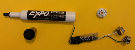
If you’re carrying around an exposed circuit board and a bunch of wires people are going to notice you. But a dry erase marker won’t turn any heads. And this one holds its own little secret. It acts as a master key for hotel room door locks.
This is really more of a repackaging hack. The exploit is already quite well-known. The Onity brand of key card locks most commonly used in hotels have a power jack on the bottom that doubles as a 1-wire communications port. The first published proof of concept used an Arduino board and a simple adapter to unlock any door in under one second. Now that hardware has been reduced in size so that it fits in the hollow shell of a dry erase marker. Even better, the felt tip has been replaced with the appropriately sized barrel jack. Check out the ultra-fast and inconspicuous use of it after the break. We think using this is no more obvious than actually having the key card.


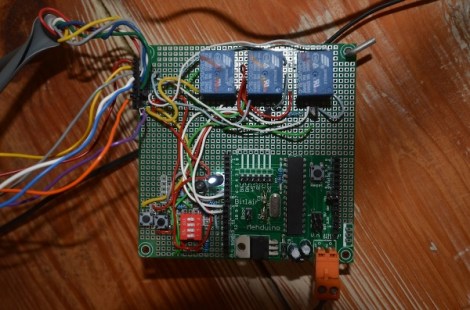
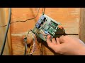
[Piet] wrote in to tell us about his hack that allows for his front gate to be opened without a key. Unlike this hack that we featured in August, you don’t need a subway pass, just a good memory. As explained in his article (and the video after the break) if the proper sequence of doorbell rings is input, the gate unlocks itself.
For hardware a [mehduino] is used to take the doorbell input and decide whether or not the “secret knock” has been achieved. The door can be unlocked remotely via a button on the processor. Reprogramming the code is achieved by simply holding the program button while the code is entered on the “remote ringer” button.
Be sure to check out the video after the break to see this lock in action. The housing application may not be exactly what you expect. Also of interest, is that in true hacker fashion, the bare processor is hanging by a hook on his wall!


[Steve] is often host to all sorts of guests, and he was looking for an easy way to let his friends come and go as they please. After discovering that his front door came equipped with an electronic strike, he decided that an RFID reader would be a great means of controlling who was let in, and when.
Giving all your friends RFID cards and actually expecting that they carry them is a bit of a stretch, but lucky for [Steve] he lives near Boston, so the MBTA has him covered. Just about everyone in town has an RFID subway pass, which pretty much guarantees that [Steve’s] cohorts will be carrying one when they swing by.
He crafted a stylish set of wooden boxes to contain both the RFID reader and the Arduino that controls the system, matching them to the Victorian styling of his home. A single button can control the setup, allowing him to add and remove cards from access lists without much fuss. For more granular control however, [Steve] can always tweak settings from the Arduino serial console.
The card system is both stylish and useful – a combination that’s hard to beat.


The security flaws on this common hotel keycard lock are nothing short of face-palmingly stupid. Look closely at the picture above. This is a hotel room door swinging open. The device he holds in his hand is an Arduino connected to the OUTSIDE portion of the door lock. It takes approximately 200 milliseconds from the time an attacker plugs the device in, until the door can be opened. Yes, in less than 1/4 of one second an Arduino can open any of the millions of these locks in service.
The exploit in Onity programmable keycard locks was revealed by [Cody Brocious] at the Blackhat conference. Apparently the DC barrel jack on the outside of the lock serves as a one-wire protocol interface. Once communications are established a 32-bit sitecode can be read from any of the locks and immediately used to open the door. There is no authentication or encryption used to obfuscate this kind of attack. To make matters worse, you can even read out master key and skeleton key codes. These codes facilitate ‘magic’ keys used to open a variety of different doors through the system.
We’re no strangers to easy hotel beak-ins. But how can a digital lock possibly be sold with this type of vulnerability present? Really!?
Here’s the white paper on the exploit as well as the slides from his talk (PDF).
[via Reddit]


Tired of dealing with keys to get into his office, Valentin Heun hacked together this door unlocker with a laser-cutter, Arduino, and some bits n’ bobs from SparkFun. Full design files and parts list can be found on the linked page.


