Posts with «laser» label

A Laser Effect Projector Built with Safety in Mind

There’s just something about wielding a laser pointer on a dark, foggy night. Watching the beam cut through the mist is fun – makes you feel a little Jedi-esque. If you can’t get enough of lasers and mist, you might want to check out this DIY “laser sky” effect projector.

The laser sky effect will probably remind you of other sci-fi movies – think of the “egg scene” from Alien. The effect is achieved by sweeping a laser beam in a plane through swirling smoke or mist. The laser highlights a cross section of the otherwise hidden air currents and makes for some trippy displays. The working principle of [Chris Guichet]’s projector is simplicity itself – an octagonal mirror spun by an old brushless fan motor and a laser pointer. But after a quick proof of concept build, he added the extras that took this from prototype to product. The little laser pointer was replaced with a 200mW laser module, the hexagonal mirror mount and case were 3D printed, and the mirrors were painstakingly aligned so the laser sweeps out a plane. An Arduino was added to control the motor and provide safety interlocks to make sure the laser fires only when the mirror is up to speed. The effect of the deep ruby red laser cutting through smoke is mesmerizing.

If laser sky is a little too one-dimensional for you, expand into two dimensions with this vector laser projector, and if monochrome isn’t your thing try an RGB vector projector.


Filed under: Arduino Hacks, laser hacks

Turning Broken Toy Into Laser Target Practice

[Mathieu] wrote in with his laser target practice game. It’s not the most amazing hack in the history of hackery, but it’s an excellent example of the type of simple and fun things you can do with just a little bit of microcontrollering.

First off, the gun is a broken toy gun that used to shoot something other than red collimated light beams. The Arduino knockoff inside reacts to a trigger pull and fires the laser for around 200 milliseconds. The gun also has a “gas gauge” that fills up with repeated shots and cools down over time. And therein lies the game — a simple race to ten, where each player only has a fixed number of shots over time.

The targets are simply a light sensor, scorekeeping LED display, and a buzzer that builds tension by beeping at you as the countdown timer ticks down. The bodies are made out of 3D-printed corners that connect some of [Mathieu]’s excess wooden goat-cheese lids.

All the code is up on GitHub so you can make your own with stuff that you’ve got lying around the house. The “gun” can be anything that you can embed a laser in that makes it aimable. Good clean fun!


Filed under: toy hacks
Hack a Day 19 Oct 00:00

Cellular Automata Explorer

Well all know cellular automata from Conway’s Game of Life which simulates cellular evolution using rules based on the state of all eight adjacent cells. [Gavin] has been having fun playing with elementary cellular automata in his spare time. Unlike Conway’s Game, elementary automata uses just the left and right neighbors of a cell to determine the next cell ahead in the row. Despite this comparative simplicity, some really complex patterns emerge, including a Turing-complete one.

[Gavin] started off doing the calculations by hand for fun. He made some nice worksheets for this. As we can easily imagine, doing the calculations by hand got boring fast. It wasn’t long before his thoughts turned to automating his cellular automata. So, he put together an automatic cellular automator. (We admit, we are having a bit of fun with this.)

This could have been a quick software project but half the fun is seeing the simulations on a purpose-built ecosystem. The files to build the device are hosted on Thingiverse. Like other cellular automata projects, it uses LED matrices to display the data. An Arduino acts as the brain and some really cool retro switches from the world’s most ridiculously organized electronics collection finish the look of the project.

To use, enter the starting condition with the switches at the bottom. The code on the Arduino then computes and displays the pattern on the matrix. Pretty cool and way faster than doing it by hand.


Filed under: Arduino Hacks, misc hacks

Arduino based Security Project Using Cayenne


Description

This is an Arduino based home security project that uses the power of "Cayenne" for extraordinary capabilities.

Cayenne Beta

Cayenne is a new IoT drag and drop platform originally released for the Raspberry Pi, but now available for Arduino. Cayenne makes the task of connecting your Arduino to the internet as simple as possible. All of the complexity of internet connectivity is hidden within the Cayenne library.

You can easily create a Network of Arduinos and build an IoT system which can be managed and operated within the Cayenne dashboard. This dashboard is accessible through your browser or via the Cayenne smart phone app (on IOS or Android).

The feature I liked the most, was the ability to change the position of sensors or actuators on the Arduino without having to re-upload Arduino code. I could manage the changed position from within the Cayenne platform. The other feature that I liked was the ability to setup actions based on custom triggers. You can use Cayenne to trigger a whole range of functions, for example: play a sound, move a motor, light up an LED, or to send alert notifications via email or SMS.

Cayenne is in Beta at the moment, so there are a few minor bugs here and there, but overall - I give it a thumbs up - it is definitely worth checking out.
 

Here is a link to the Cayenne Beta Program:
**Cayenne Beta Link**


              Source: myDevices Media Kit


Home Security Project Summary

In order to fully experience this new IoT platform, I decided to create a project to really put it through its paces. This is what my Security Project will need:

  1. It will use two Arduinos, one connected to the internet via an Ethernet shield, and the other via WIFI.
  2. Two detectors - a PIR sensor and a laser trip wire.
  3. If the sensors are tripped, the person has 10 seconds to present an RFID tag to the Grove RFID reader:
    • If a valid RFID tag is SUCCESSFULLY presented within the time limit, a nice personalised greeting will be played to that person using a Grove - Serial MP3 player
    • If a valid RFID FAILS to be presented within the time limit, an Alarm will sound, and I will be notified of the intrusion via an SMS alert.
  4. The Cayenne dashboard will show the status of the sensors, and I will have full control over my security system via the web interface (or smartphone app).
  5. The sensors will be attached to a different Arduino to that of the Grove MP3 player and the RFID tag reader, which means that there will have to be some level of communication between the two Arduinos. In fact, the cross communication will be vital to the success of this project.


Project Video


Flow Diagrams:

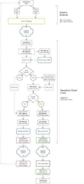
Main Flow Diagram

The following flow diagram shows the Security project process. It is a high level view of the decisions being made by each Arduino in response to various events.  


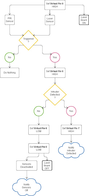
Triggers Flow Diagram

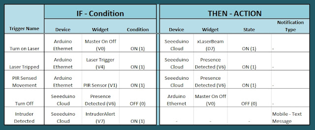
The following flow diagram aims to highlight the various triggers set up within Cayenne to get this Security system to work.  


Arduino IDE and Library Downloads

You will need an Arduino IDE to upload code to the Arduino and the Seeeduino Cloud.
Here is the link to the Arduino IDE: Arduino IDE - download location

The Cayenne service requires that you download and install the Cayenne Library into your Arduino IDE.
You can get the Cayenne Library from here: Cayenne Library File - Download


Cayenne Connectivity Setup

The Seeeduino Cloud needs to be prepared for use with Cayenne.
Normal operating/setup instructions can be found here: Seeeduino Cloud WIKI page
 
Once you have successfully connected Seeeduino Cloud to your WIFI network, you can add it to the Cayenne Dashboard by making the following selections from within the Cayenne Web application:

  1. Add New
  2. Device/Widget
  3. Microcontrollers
  4. Arduino
  5. Ensure Seeeduino Cloud is connected to WIFI network - the select the NEXT button
  6. Select - Arduino Yun: Built-in Ethernet - ticked
  7. Providing you have already installed the Cayenne library as described above - you should be able to copy and paste the code to the Arduino IDE and upload to the Seeeduino Cloud.
  8. If successful, you should see the Arduino Yun board appear within the Cayenne Dashboard. If not, then seek help within the Cayenne forum.


The Arduino UNO with WIZNET 5100 - Ethernet Shield
also needs to be prepared with Cayenne

  1. Add New
  2. Device/Widget
  3. Microcontrollers
  4. Arduino
  5. Ensure Arduino is powered, and Ethernet shield is connected to your internet router via an Ethernet cable
  6. Select - Arduino Uno: Ethernet Shield W5100 - ticked
  7. Copy and paste the code to the Arduino IDE and upload to the Arduino UNO.
  8. If successful, you should see the Arduino Uno board appear within the Cayenne Dashboard. If not, then seek help within the Cayenne forum.


If you have the Ethernet shield with the WIZNET 5200 chip, then you may need to download a specific Ethernet library in addition to the Cayenne library.
 
Just follow the instructions within the Automatically generated sketch provided - when you select your specific Arduino/Ethernet/WIFI shield combination. If you need further instructions on connecting your device to Cayenne - then please visit the myDevices website for the online documentation.


ARDUINO CODE (1)


Code for Arduino UNO with Ethernet Shield:

The following code will need to be uploaded to the Arduino UNO:


ARDUINO CODE (2)


Code for Seeeduino Cloud:

The following code will need to be uploaded to the Seeeduino Cloud:


Fritzing diagram (1)


Fritzing diagram for Arduino UNO with Ethernet

Please click on the picture below for an enlarged version of this fritzing diagram


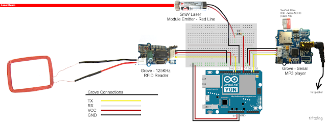
Fritzing diagram (2)


Fritzing diagram for Seeeduino Cloud

Please click on the picture below for an enlarged version of this fritzing diagram


Cayenne Dashboard Setup - GUI


The Arduino code only provides half of the functionality of this project. The Cayenne Dashboard needs to be setup to provide the rest of the functionality. The following instructions will show you how to add each of the widgets required for this Home Security project.


Arduino Ethernet - Master Switch

The master switch allows me to turn the security system on and off. When I turn the MASTER SWITCH ON, the laser beam will turn on, and the sensors will start monitoring the area for intruders. This widget is NOT associated with a physical switch/sensor on the Arduino - it uses virtual channel 0. We need to add the Master switch to the dashboard:


  1. Add New
  2. Device/Widget
  3. Actuators
  4. Generic
  5. Digital Output - Control a Digital Output
  6. Widget Name: Master On Off Switch
  7. Select Device: Arduino Ethernet
  8. Connectivity: Virtual
  9. Pin: V0
  10. Choose Widget: Button
  11. Choose Icon: Valve
  12. Step2: Add Actuator
We will add a trigger later to get this button to automatically turn the Laser beam on.


Arduino Ethernet - PIR Sensor

This sensor will be used to detect movement in the room. If a person walks into the room, this sensor will detect movement, and will trigger a message to be played on the Grove Serial MP3 player. The message will aim to get the person to identify themselves. They identify themselves by placing their RFID tag in close proximity to the Grove RFID reader. If the tag is valid, a "Welcome home" message is played on the Grove MP3 player. If a valid tag is not presented to the reader within 10 seconds, an Alarm will go off ("Alarm sound" played on Grove MP3 player.)
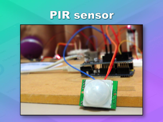
The PIR sensor is connected to digital Pin 6 of the Arduino, however, it is mapped to virtual pin 1 for better synchronisation with the Cayenne dashboard. This was done to capture ALL detections - as the PIR sensor could change from a LOW to HIGH and back to LOW state in between a Cayenne state check - and therefore, Cayenne could miss this motion detection.. Therefore we need to assign the PIR sensor to a virtual channel in the following way:
  1. Add New
  2. Device/Widget
  3. Sensors
  4. Motion
  5. Digital Motion Sensor - Motion Detector
  6. Widget Name: PIR sensor
  7. Select Device: Arduino Ethernet
  8. Connectivity: Virtual
  9. Pin: V1
  10. Choose Widget: 2-State Display
  11. Choose Icon: Light
  12. Step2: Add Sensor
  13. Select Settings from the PhotoResistor
  14. Choose Display: Value
  15. Save


Arduino Ethernet - Photoresistor

This sensor will be used with the laser beam to create a laser tripwire. If the sensor detects a change in light levels (drops below the threshold), it will activate the laser trigger button on the dashboard. The person will then be required to identify themselves etc etc (similar to the motion detection by the PIR sensor). The photoresistor widget will display the raw analog reading from the sensor (connected to A2), but is associated with virtual channel 2. I used a virtual channel for more control over this sensor. To add the Photoresistor to the dashboard:

  1. Add New
  2. Device/Widget
  3. Sensors
  4. Luminosity
  5. Photoresistor - Luminosity sensor
  6. Widget Name: PhotoResistor
  7. Select Device: Arduino Ethernet
  8. Connectivity: Virtual
  9. Pin: V2
  10. Choose Widget: Value
  11. Choose Icon: Light
  12. Step2: Add Sensor


Arduino Ethernet - Laser Trigger

The laser trigger is just an indicator that someone tripped the laser beam. The state of this widget is used to notify the Seeeduino that a presence has been detected. This widget is associated with virtual pin 4 on the Arduino UNO with Ethernet.

  1. Add New
  2. Device/Widget
  3. Actuators
  4. Generic
  5. Digital Output - Control a Digital Output
  6. Widget Name: Laser Trigger
  7. Select Device: Arduino Ethernet
  8. Connectivity: Virtual
  9. Pin: V4
  10. Choose Widget: Button
  11. Choose Icon: Lock
  12. Step2: Add Actuator


Arduino Ethernet - Laser Threshold

The laser threshold is used to manually configure the light level at which the laser trigger will trip. When the photoresistor value drops below the threshold value, the laser trigger icon will activate. This allows the threshold value to be updated from the Cayenne dashboard, rather than having to manually adjust the value in the Arduino code. Also, this threshold can be set remotely, in that you don't have to be near the Arduino to change this value. A very useful feature of this Security system. This widget is associated with virtual pin 5 on the Arduino UNO with Ethernet.

  1. Add New
  2. Device/Widget
  3. Actuators
  4. Generic
  5. PWM Output - Control a PWM Output
  6. Widget Name: Laser Threshold
  7. Select Device: Arduino Ethernet
  8. Connectivity: Virtual
  9. Pin: V5
  10. Choose Widget: Slider
  11. Slider Min Value: 0
  12. Slider Max Value: 10
  13. Step2: Add Actuator
The max value of the slider is 10 - due to a current bug in the Cayenne software. Once resolved, this value (as well as the relevant Arduino code) will need to be updated.


Seeeduino Cloud - Presence Detected

The presence detected widget is there to notify the Seeeduino Cloud that a presence has been detected on the Arduino Uno with Ethernet shield. When the PIR sensor detects movement or if the laser tripwire is tripped, Cayenne will change the state of the Presence Detected widget from LOW to HIGH. This is used within the Seeeduino Cloud to trigger the message "Place your keys on the Mat"
. If a valid RFID tag is read by the Grove RFID reader, then this widget's state will change back from HIGH to LOW, and the MasterSwitch will be deactivated - turning the Security system off. This widget is associated with Virtual pin 6 on the Seeeduino Cloud.

  1. Add New
  2. Device/Widget
  3. Actuators
  4. Generic
  5. Digital Output - Control a Digital Output
  6. Widget Name: Presence Detected
  7. Select Device: Seeeduino Cloud
  8. Connectivity: Virtual
  9. Pin: V6
  10. Choose Widget: Button
  11. Choose Icon: Lock
  12. Step2: Add Actuator


Seeeduino Cloud - Intruder Alert

If a valid RFID tag is not read by the Grove RFID reader within 10 seconds of a presence detection event, an alarm will sound, and this widget will be activated. This will trigger a notification event - to notify me of the unauthorised intrusion - via SMS or email. I will also have a visual indicator on the Cayenne dashboard that an intrusion has taken place. This widget is associated with Virtual pin 7 on the Seeeduino Cloud.

  1. Add New
  2. Device/Widget
  3. Actuators
  4. Generic
  5. Digital Output - Control a Digital Output
  6. Widget Name: Laser Trigger
  7. Select Device: Seeeduino Cloud
  8. Connectivity: Virtual
  9. Pin: V7
  10. Choose Widget: Button
  11. Choose Icon: Thermometer
  12. Step2: Add Actuator


Seeeduino Cloud - Laser Beam

The laser beam widget was created to allow for full control over the laser beam. The laser beam can be turned on or off from the Cayenne dashboard, and a connected to digital pin 7 on the Seeeduino Cloud.


  1. Add New
  2. Device/Widget
  3. Actuators
  4. Light
  5. Light Switch - Turn On/Off a Light
  6. Widget Name: xLaser Beam
  7. Select Device: Seeeduino Cloud
  8. Connectivity: Digital
  9. Pin: D7
  10. Choose Widget: Button
  11. Choose Icon: Light
  12. Step2: Add Actuator


Cayenne Triggers

Now that all of the widgets have been added to the Dashboard, there is just one more step to complete the Security System. We need to setup the triggers. These triggers provide a level of automation that is easy to create within Cayenne, but would be very complicated otherwise. I set my triggers up as per the table below. Each row represents one of the triggers within my Cayenne dashboard. If you would like to see an example of how to add a trigger - please have a look at the video at the top of this tutorial.  


Concluding comments

I used many different elements to put this home/office security project together - Multiple Arduinos were connected to the internet, both controlled by a web/smart phone app, cross-communication/synchronisation between the Arduinos, and the use of multiple sensors and modules including a laser beam !
 
This was way more than just a simple PIR sense and alarm project. I now have a personalised greeting and reminder system when I walk in the door. Everyone else has their own personalised greeting. I can enable my Security System remotely, from two blocks away, and if I wanted to - I could enable it from the other side of the world. I know instantly when someone has entered my house/office.... with an SMS alert straight to my phone.
 
This project could easily be extended:

  1. Press a button on my phone to manually trigger/play a specific message/sound/song
  2. Take a picture of the intruder
  3. Introduce fire or leak detection aswell
  4. Add other environmental sensors - Temperature / Humidity
  5. Connect it to lamp/light - creating a security light
I am sure you can think of more things I could do with this system. In fact, why don't you mention your ideas in the comments below.
 
Cayenne was instrumental in getting this project to work. I don't think I would know where to start if I had to do this project without this cool IoT platform. I think I will definitely be trying out a few more projects using Cayenne, and should you want to do the same, then please make sure to join Cayenne Beta:
 
Here is the link you need to get to the right place: Cayenne Beta Link


If you like this page, please do me a favour and show your appreciation :

 
Visit my ArduinoBasics Google + page.
Follow me on Twitter by looking for ScottC @ArduinoBasics.
I can also be found on Pinterest and Instagram.
Have a look at my videos on my YouTube channel.


ScottC 02 Sep 05:11
alarm  arduino  arduinobasics  cayenne  laser  mp3  mydevices  pir  rfid  security  sms  tutorial  

Arduino based Security Project Using Cayenne


Description

This is an Arduino based home security project that uses the power of "Cayenne" for extraordinary capabilities.

Cayenne Beta

Cayenne is a new IoT drag and drop platform originally released for the Raspberry Pi, but now available for Arduino. Cayenne makes the task of connecting your Arduino to the internet as simple as possible. All of the complexity of internet connectivity is hidden within the Cayenne library.

You can easily create a Network of Arduinos and build an IoT system which can be managed and operated within the Cayenne dashboard. This dashboard is accessible through your browser or via the Cayenne smart phone app (on IOS or Android).

The feature I liked the most, was the ability to change the position of sensors or actuators on the Arduino without having to re-upload Arduino code. I could manage the changed position from within the Cayenne platform. The other feature that I liked was the ability to setup actions based on custom triggers. You can use Cayenne to trigger a whole range of functions, for example: play a sound, move a motor, light up an LED, or to send alert notifications via email or SMS.

Cayenne is in Beta at the moment, so there are a few minor bugs here and there, but overall - I give it a thumbs up - it is definitely worth checking out.
 

Here is a link to the Cayenne Beta Program:
**Cayenne Beta Link**


              Source: myDevices Media Kit


Home Security Project Summary

In order to fully experience this new IoT platform, I decided to create a project to really put it through its paces. This is what my Security Project will need:

  1. It will use two Arduinos, one connected to the internet via an Ethernet shield, and the other via WIFI.
  2. Two detectors - a PIR sensor and a laser trip wire.
  3. If the sensors are tripped, the person has 10 seconds to present an RFID tag to the Grove RFID reader:
    • If a valid RFID tag is SUCCESSFULLY presented within the time limit, a nice personalised greeting will be played to that person using a Grove - Serial MP3 player
    • If a valid RFID FAILS to be presented within the time limit, an Alarm will sound, and I will be notified of the intrusion via an SMS alert.
  4. The Cayenne dashboard will show the status of the sensors, and I will have full control over my security system via the web interface (or smartphone app).
  5. The sensors will be attached to a different Arduino to that of the Grove MP3 player and the RFID tag reader, which means that there will have to be some level of communication between the two Arduinos. In fact, the cross communication will be vital to the success of this project.


Project Video


Flow Diagrams:

Main Flow Diagram

The following flow diagram shows the Security project process. It is a high level view of the decisions being made by each Arduino in response to various events.  


Triggers Flow Diagram

The following flow diagram aims to highlight the various triggers set up within Cayenne to get this Security system to work.  


Arduino IDE and Library Downloads

You will need an Arduino IDE to upload code to the Arduino and the Seeeduino Cloud.
Here is the link to the Arduino IDE: Arduino IDE - download location

The Cayenne service requires that you download and install the Cayenne Library into your Arduino IDE.
You can get the Cayenne Library from here: Cayenne Library File - Download


Cayenne Connectivity Setup

The Seeeduino Cloud needs to be prepared for use with Cayenne.
Normal operating/setup instructions can be found here: Seeeduino Cloud WIKI page
 
Once you have successfully connected Seeeduino Cloud to your WIFI network, you can add it to the Cayenne Dashboard by making the following selections from within the Cayenne Web application:

  1. Add New
  2. Device/Widget
  3. Microcontrollers
  4. Arduino
  5. Ensure Seeeduino Cloud is connected to WIFI network - the select the NEXT button
  6. Select - Arduino Yun: Built-in Ethernet - ticked
  7. Providing you have already installed the Cayenne library as described above - you should be able to copy and paste the code to the Arduino IDE and upload to the Seeeduino Cloud.
  8. If successful, you should see the Arduino Yun board appear within the Cayenne Dashboard. If not, then seek help within the Cayenne forum.


The Arduino UNO with WIZNET 5100 - Ethernet Shield
also needs to be prepared with Cayenne

  1. Add New
  2. Device/Widget
  3. Microcontrollers
  4. Arduino
  5. Ensure Arduino is powered, and Ethernet shield is connected to your internet router via an Ethernet cable
  6. Select - Arduino Uno: Ethernet Shield W5100 - ticked
  7. Copy and paste the code to the Arduino IDE and upload to the Arduino UNO.
  8. If successful, you should see the Arduino Uno board appear within the Cayenne Dashboard. If not, then seek help within the Cayenne forum.


If you have the Ethernet shield with the WIZNET 5200 chip, then you may need to download a specific Ethernet library in addition to the Cayenne library.
 
Just follow the instructions within the Automatically generated sketch provided - when you select your specific Arduino/Ethernet/WIFI shield combination. If you need further instructions on connecting your device to Cayenne - then please visit the myDevices website for the online documentation.


ARDUINO CODE (1)


Code for Arduino UNO with Ethernet Shield:

The following code will need to be uploaded to the Arduino UNO:


ARDUINO CODE (2)


Code for Seeeduino Cloud:

The following code will need to be uploaded to the Seeeduino Cloud:


Fritzing diagram (1)


Fritzing diagram for Arduino UNO with Ethernet

Please click on the picture below for an enlarged version of this fritzing diagram


Fritzing diagram (2)


Fritzing diagram for Seeeduino Cloud

Please click on the picture below for an enlarged version of this fritzing diagram


Cayenne Dashboard Setup - GUI


The Arduino code only provides half of the functionality of this project. The Cayenne Dashboard needs to be setup to provide the rest of the functionality. The following instructions will show you how to add each of the widgets required for this Home Security project.


Arduino Ethernet - Master Switch

The master switch allows me to turn the security system on and off. When I turn the MASTER SWITCH ON, the laser beam will turn on, and the sensors will start monitoring the area for intruders. This widget is NOT associated with a physical switch/sensor on the Arduino - it uses virtual channel 0. We need to add the Master switch to the dashboard:


  1. Add New
  2. Device/Widget
  3. Actuators
  4. Generic
  5. Digital Output - Control a Digital Output
  6. Widget Name: Master On Off Switch
  7. Select Device: Arduino Ethernet
  8. Connectivity: Virtual
  9. Pin: V0
  10. Choose Widget: Button
  11. Choose Icon: Valve
  12. Step2: Add Actuator
We will add a trigger later to get this button to automatically turn the Laser beam on.


Arduino Ethernet - PIR Sensor

This sensor will be used to detect movement in the room. If a person walks into the room, this sensor will detect movement, and will trigger a message to be played on the Grove Serial MP3 player. The message will aim to get the person to identify themselves. They identify themselves by placing their RFID tag in close proximity to the Grove RFID reader. If the tag is valid, a "Welcome home" message is played on the Grove MP3 player. If a valid tag is not presented to the reader within 10 seconds, an Alarm will go off ("Alarm sound" played on Grove MP3 player.)

The PIR sensor is connected to digital Pin 6 of the Arduino, however, it is mapped to virtual pin 1 for better synchronisation with the Cayenne dashboard. This was done to capture ALL detections - as the PIR sensor could change from a LOW to HIGH and back to LOW state in between a Cayenne state check - and therefore, Cayenne could miss this motion detection.. Therefore we need to assign the PIR sensor to a virtual channel in the following way:
  1. Add New
  2. Device/Widget
  3. Sensors
  4. Motion
  5. Digital Motion Sensor - Motion Detector
  6. Widget Name: PIR sensor
  7. Select Device: Arduino Ethernet
  8. Connectivity: Virtual
  9. Pin: V1
  10. Choose Widget: 2-State Display
  11. Choose Icon: Light
  12. Step2: Add Sensor
  13. Select Settings from the PhotoResistor
  14. Choose Display: Value
  15. Save


Arduino Ethernet - Photoresistor

This sensor will be used with the laser beam to create a laser tripwire. If the sensor detects a change in light levels (drops below the threshold), it will activate the laser trigger button on the dashboard. The person will then be required to identify themselves etc etc (similar to the motion detection by the PIR sensor). The photoresistor widget will display the raw analog reading from the sensor (connected to A2), but is associated with virtual channel 2. I used a virtual channel for more control over this sensor. To add the Photoresistor to the dashboard:

  1. Add New
  2. Device/Widget
  3. Sensors
  4. Luminosity
  5. Photoresistor - Luminosity sensor
  6. Widget Name: PhotoResistor
  7. Select Device: Arduino Ethernet
  8. Connectivity: Virtual
  9. Pin: V2
  10. Choose Widget: Value
  11. Choose Icon: Light
  12. Step2: Add Sensor


Arduino Ethernet - Laser Trigger

The laser trigger is just an indicator that someone tripped the laser beam. The state of this widget is used to notify the Seeeduino that a presence has been detected. This widget is associated with virtual pin 4 on the Arduino UNO with Ethernet.

  1. Add New
  2. Device/Widget
  3. Actuators
  4. Generic
  5. Digital Output - Control a Digital Output
  6. Widget Name: Laser Trigger
  7. Select Device: Arduino Ethernet
  8. Connectivity: Virtual
  9. Pin: V4
  10. Choose Widget: Button
  11. Choose Icon: Lock
  12. Step2: Add Actuator


Arduino Ethernet - Laser Threshold

The laser threshold is used to manually configure the light level at which the laser trigger will trip. When the photoresistor value drops below the threshold value, the laser trigger icon will activate. This allows the threshold value to be updated from the Cayenne dashboard, rather than having to manually adjust the value in the Arduino code. Also, this threshold can be set remotely, in that you don't have to be near the Arduino to change this value. A very useful feature of this Security system. This widget is associated with virtual pin 5 on the Arduino UNO with Ethernet.

  1. Add New
  2. Device/Widget
  3. Actuators
  4. Generic
  5. PWM Output - Control a PWM Output
  6. Widget Name: Laser Threshold
  7. Select Device: Arduino Ethernet
  8. Connectivity: Virtual
  9. Pin: V5
  10. Choose Widget: Slider
  11. Slider Min Value: 0
  12. Slider Max Value: 10
  13. Step2: Add Actuator
The max value of the slider is 10 - due to a current bug in the Cayenne software. Once resolved, this value (as well as the relevant Arduino code) will need to be updated.


Seeeduino Cloud - Presence Detected

The presence detected widget is there to notify the Seeeduino Cloud that a presence has been detected on the Arduino Uno with Ethernet shield. When the PIR sensor detects movement or if the laser tripwire is tripped, Cayenne will change the state of the Presence Detected widget from LOW to HIGH. This is used within the Seeeduino Cloud to trigger the message "Place your keys on the Mat"
. If a valid RFID tag is read by the Grove RFID reader, then this widget's state will change back from HIGH to LOW, and the MasterSwitch will be deactivated - turning the Security system off. This widget is associated with Virtual pin 6 on the Seeeduino Cloud.

  1. Add New
  2. Device/Widget
  3. Actuators
  4. Generic
  5. Digital Output - Control a Digital Output
  6. Widget Name: Presence Detected
  7. Select Device: Seeeduino Cloud
  8. Connectivity: Virtual
  9. Pin: V6
  10. Choose Widget: Button
  11. Choose Icon: Lock
  12. Step2: Add Actuator


Seeeduino Cloud - Intruder Alert

If a valid RFID tag is not read by the Grove RFID reader within 10 seconds of a presence detection event, an alarm will sound, and this widget will be activated. This will trigger a notification event - to notify me of the unauthorised intrusion - via SMS or email. I will also have a visual indicator on the Cayenne dashboard that an intrusion has taken place. This widget is associated with Virtual pin 7 on the Seeeduino Cloud.

  1. Add New
  2. Device/Widget
  3. Actuators
  4. Generic
  5. Digital Output - Control a Digital Output
  6. Widget Name: Laser Trigger
  7. Select Device: Seeeduino Cloud
  8. Connectivity: Virtual
  9. Pin: V7
  10. Choose Widget: Button
  11. Choose Icon: Thermometer
  12. Step2: Add Actuator


Seeeduino Cloud - Laser Beam

The laser beam widget was created to allow for full control over the laser beam. The laser beam can be turned on or off from the Cayenne dashboard, and a connected to digital pin 7 on the Seeeduino Cloud.


  1. Add New
  2. Device/Widget
  3. Actuators
  4. Light
  5. Light Switch - Turn On/Off a Light
  6. Widget Name: xLaser Beam
  7. Select Device: Seeeduino Cloud
  8. Connectivity: Digital
  9. Pin: D7
  10. Choose Widget: Button
  11. Choose Icon: Light
  12. Step2: Add Actuator


Cayenne Triggers

Now that all of the widgets have been added to the Dashboard, there is just one more step to complete the Security System. We need to setup the triggers. These triggers provide a level of automation that is easy to create within Cayenne, but would be very complicated otherwise. I set my triggers up as per the table below. Each row represents one of the triggers within my Cayenne dashboard. If you would like to see an example of how to add a trigger - please have a look at the video at the top of this tutorial.  


Concluding comments

I used many different elements to put this home/office security project together - Multiple Arduinos were connected to the internet, both controlled by a web/smart phone app, cross-communication/synchronisation between the Arduinos, and the use of multiple sensors and modules including a laser beam !
 
This was way more than just a simple PIR sense and alarm project. I now have a personalised greeting and reminder system when I walk in the door. Everyone else has their own personalised greeting. I can enable my Security System remotely, from two blocks away, and if I wanted to - I could enable it from the other side of the world. I know instantly when someone has entered my house/office.... with an SMS alert straight to my phone.
 
This project could easily be extended:

  1. Press a button on my phone to manually trigger/play a specific message/sound/song
  2. Take a picture of the intruder
  3. Introduce fire or leak detection aswell
  4. Add other environmental sensors - Temperature / Humidity
  5. Connect it to lamp/light - creating a security light
I am sure you can think of more things I could do with this system. In fact, why don't you mention your ideas in the comments below.
 
Cayenne was instrumental in getting this project to work. I don't think I would know where to start if I had to do this project without this cool IoT platform. I think I will definitely be trying out a few more projects using Cayenne, and should you want to do the same, then please make sure to join Cayenne Beta:
 
Here is the link you need to get to the right place: Cayenne Beta Link


If you like this page, please do me a favour and show your appreciation :

 
Visit my ArduinoBasics Google + page.
Follow me on Twitter by looking for ScottC @ArduinoBasics.
I can also be found on Pinterest and Instagram.
Have a look at my videos on my YouTube channel.


ScottC 30 Aug 15:42
alarm  arduino  arduinobasics  cayenne  laser  mp3  mydevices  pir  rfid  security  sms  tutorial  

Autonomous Musical Soundscapes from 42 Fans and 7 Lasers

[dmitry] writes in to let us know about a new project that combines lasers with fans and turns the resulting modulation of the light beams into an autonomous soundscape. The piece is called “divider” and is a large, wall-mounted set of rails upon which seven red lasers are mounted on one end with seven matching light sensors mounted on the other end. Interrupting the lasers’ paths are forty-two brushless fans. Four Arduino Megas control the unit.

Laser beams shining into light sensors don’t do much of anything on their own, but when spinning fan blades interrupt each laser beam it modulates the solid beams and turns the readings of the sensors on the far end into a changing electrical signal which can be played as sound. Light being modulated by fan blades to create sound is the operating principle behind a Fan Synth, which we’ve discussed before as being a kind of siren (or you can go direct to that article’s fan synth demo video to hear what kind of sounds are possible from such a system.)

This project takes this entire concept of a fan synth further by not only increasing the number of lasers and fans, but by tying it all together into an autonomous system. The lasers are interrupted repeatedly and constantly, but never simultaneously. Listen to and watch it in action in the video below.

There isn’t a lot of in-depth technical information on the project page, but there are many really good photos. We especially love the way that the whole assembly is highly visual with the lasers turning on and off and interacting with different fans.

Any changing electrical signal can be played as sound, and if there’s one thing projects like self-playing musical hardware can teach us, it’s that if you have an electrical signal that looks strange or chaotic, hook a speaker up to it because it probably sounds pretty cool!


Filed under: musical hacks

Don’t Take Photos of Your Arduino 101 Either, Its Light Sensitive

Wafer level chips are cheap and very tiny, but as [Kevin Darrah] shows, vulnerable to bright light without the protective plastic casings standard on other chip packages.

We covered a similar phenomenon when the Raspberry Pi 2 came out. A user was taking photos of his Pi to document a project. Whenever his camera flash went off, it would reset the board.

[Kevin] got a new Arduino 101 board into his lab. The board has a processor from Intel, an accelerometer, and Bluetooth Low Energy out of the box while staying within the same relative price bracket as the Atmel versions. He was admiring the board, when he noticed that one of the components glittered under the light. Curious, he pulled open the schematic for the board, and found that it was the chip that switched power between the barrel jack and the USB. Not only that, it was a wafer level package.

So, he got out his camera and a laser. Sure enough, both would cause the power to drop off for as long as the package was exposed to the strong light. The Raspberry Pi foundation later wrote about this phenomenon in more detail. They say it won’t affect normal use, but if you’re going to expose your device to high energy light, simply put it inside a case or cover the chip with tape, Sugru, or a non-conductive paint to shield it.


Filed under: Arduino Hacks
Hack a Day 06 May 00:01

UV Laser Projector Shines With Glow-in-the-Dark Vinyl

Mirror galvanometers were originally developed in the 17th century to precisely measure very small changes in current. Unlike other instruments of the day, a mirror galvanometer could clearly show minute current variations by translating tiny movements of the mirror into large movements of the light reflected off of the mirror. Before clean electrical amplification became possible, this was the best means of measuring tiny differences in current. True mirror galvanometers are very sensitive instruments, but hobby servos can be used as a low-fidelity alternative, like with this project on Hackaday.io created by [robives].

Using a mirror galvanometer is by far the most common technique for laser projection shows – it’s really the only way to move the laser’s beam quickly enough to create the visual illusion of a solid line in real time. A mirror galvanometer works by using coils to attract magnets attached to the mirror, allowing the angle of the mirror to change when current is applied to the coils. This movement is extremely small, but is amplified by the distance to the projection surface, meaning the laser’s beam can move huge distances in an instance. If you’ve ever seen a laser show, it almost certainly used this technique. But driving galvos requires a beefy DAC, so we can’t blame [robives] for wanting to keep it digital.

[robives’s] project side-steps the need for galvanometers by using glow-in-the-dark vinyl and a UV laser. The result is a laser beam trail which lasts much longer, which means that solid lines are visible without the need for high-speed galvos. A build like this lets you experiment with laser projections without dealing with sensitive mirror galvos, and instead use components that you probably already have sitting on your workbench.


Filed under: laser hacks
Hack a Day 02 Dec 03:00

Laser Rangefinder Brought to Life With Arduino

Range finders are amazing tools for doing pretty much anything involving distance calculations. Want to blink some lights when people are nearby? There’s a rangefinder for that. Need to tell how far away the next peak of a mountain range is? There’s a rangefinder for that. But if you’re new to range finders and want one that’s hackable and configurable, look no further than the SF02/F rangefinder with the Arduino shield, and [Laser Developer]’s dive into what this pair can do.

Once the rangefinder and shield have been paired is when the magic really starts to happen. Using USB, the Arduino can instantly report a huge amount of raw data coming from the rangefinder. From there, [Laser Developer] shows us how to put the device into a “settings” mode which expands the capabilities of the rangefinder even more. The data can be dumped into a graph, for example, which can show trends between distance, laser strength, and many other data sets. [Laser Developer] goes one step further and demonstrates how to use this to calculate the speed of light, but from there pretty much anything else is possible as well.

And while you can just buy a rangefinder off the shelf, they are fairly limiting in their features and can cost exponentially more. This is a great start into using a tool like this, especially if you need specific data or have a unique application. But, if laser range finding isn’t for you or if this project is too expensive, maybe this $5 ultrasonic rangefinder will work better for your application.


Filed under: Arduino Hacks
Hack a Day 22 Oct 03:00

Listening to the sound of a 300-million-year-old disc

There’s a mineral called pyrite with a interesting nickname, fool’s gold, because it has a superficial resemblance to gold and it’s by far the most frequently mineral mistaken for gold. Even if it’s pretty abundant, there’s a rare form of pyrite which is crystallised in radial shape (as unusual disc spherulites), taking the shape of a disc. The amazing fact is that the only deposit where pyrites of such morphology are found is in Illinois (USA) and the discs are dated around 300 million years ago!

Dmitry Morozov (aka ::vtol::), a media artist living in Moscow, had the chance to use a pyrite disc and created Ra,  a sound object / synthesizer running on Arduino Nano. Ra uses laser for scanning the irregularities of the surface of the disc and further transforms this data to produce sound:

This project originated as a result of an interesting set of circumstances – a pyrite disc was given to me as a gift by a mineral seller in Boulder city (USA). Upon hearing about my works, she asked to do something with such crystal, and refused to take payment for getting it. In the same period, I was reading articles on various ways of archiving and preservation of sounds from the first, historical sources of the recorded sound – wax discs and other fragile carriers. All technologies were based on the usage of lasers. Inspired by these projects, I set out to create a self-made laser sound reader which would be able to produce sound from various uneven surfaces, using minimal resources to achive it. Thus emerged the idea to construct an instrument using the pyrite disc and a self-made laser sound reader.

The production of the object was possible thanks to the commission of the Sound Museum in St.-Petersburg which now has Ra in its collection.

Check the bill of materials and other details on Dmitry’s website. Explore other projects by Dmitry featured on Arduino Blog.

Arduino Blog 05 Oct 12:54