Posts with «kl25z» label

Mac OS 10.6.8 kernel bug

Today I managed to tickle a rather nasty kernel bug in Mac OS 10.6.8 on my laptop.  The bug resulted in unkillable zombie processes—including one stuck in a busy-wait loop that took up 100% of the CPU (in kernel mode). You can’t kill the processes (not even “kill -9″ works), and you can’t shut down or restart the computer—only power cycling works.

Here is how I tickled the bug:

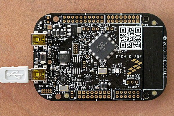
  1. I had a KL25Z board plugged into a USB slot, providing data at 115200 baud.
  2. I started a python program that read the stream from the USB and echoed it to the terminal window:
    #!/usr/bin/env python
    
    from __future__ import print_function,division
    from glob import glob
    from serial import Serial
    
    USB_serial_ports = glob("/dev/tty.usb*")
    print ("# Possible ports = {}".format(USB_serial_ports))
    usb_serial = Serial(USB_serial_ports[0],baudrate=115200,timeout=5);
    print ("# Opened {}".format(usb_serial))
    
    try:
        for line in usb_serial:
           print (line.strip())
    except KeyboardInterrupt:
        usb_serial.close()
    
  3. I used ^C to kill the python program and close the port.  So far, everything was working great.  The program echoed the stream from the KL25Z board nicely to the terminal window, and the try-except block caught the ^C interrupt and (presumably) closed the port.
  4. I started the python program again.  This time, it was unable to open the USB serial port (never getting to the “Opened” print statement), and could not be killed. The Activity Monitor showed that the kernel was using 100% of a CPU core (I have a dual-core MacBook Pro, so this was only half the available CPU). I tried ^C, Force Quit, and “kill -9″ with the process number of the Python process—none had any effect. ^Z claimed that the process was suspended, but the kernel was still in a busy-wait loop, and attempting to kill the suspended process had no effect on either the kernel busy-wait or the Python process.
  5. Unplugging the USB cable stopped the kernel busy-wait loop (at least the system CPU usage dropped from 100% down to 2%), but the Python process was still unkillable.

I could do this cycle repeatedly, since each time I plugged in the cable to the KL25Z board the Mac assigned a new device number, and I could thereby build up a lot of unkillable Python processes.  Eventually, I got tired of the large number of unkillable processes, and tried restarting the computer.  It got to the blue screen, then spun the waiting icon forever (well, longer than I was willing to wait), so I had to use option-power to turn off the computer.  It rebooted fine.

I have so such trouble with the Arduino Duemilanove board (which resets whenever the USB serial port is opened).  The same Python program also works fine with the Arduino Leonardo board, which does not reset.  I can run my little echoing program, ^C it, and run it again to continue getting the stream from the board.

There must be some difference between how the Leonardo sets up the USB serial connection and how the KL25Z board does it—a difference that causes a kernel busy-wait when reopening the stream from the KL25Z, but not when re-opening the stream from the Leonardo.  Since the default serial setup is the same for both, I’m a little mystified what that could be.

Of course, I’m now left with a bit of a dilemma—how do I record data from the KL25Z board without having to unplug and replug the USB cable for every event I want to record?

I looked around the Web to see if anyone else had similar problems.  It does seem to have been a problem with OS 10.6 in other USB contexts:

http://support.plugable.com/plugable/topics/baud_rate_switches_cause_driver_hangs_in_the_kernel

http://stackoverflow.com/questions/4064832/open-function-hangs-never-returns-when-trying-to-open-serial-port-in-mac-os

And the stackoverflow answers suggest that the problem is buggy device driver, but I’ve no idea which device driver either the Leonardo or the KL25Z board (with MBED firmware) causes to be used on the Mac.  Are they using different drivers?  How do I find out?


According to the USB Prober application, the KL25Z board opens with

           4: MBED CMSIS-DAP@4100000  <class IOUSBDevice>
               AppleUSBCDC  <class AppleUSBCDC>
               USB_MSC@0  <class IOUSBInterface>
                   IOUSBMassStorageClass  <class IOUSBMassStorageClass>
               IOUSBInterface@1  <class IOUSBInterface>
                   AppleUSBCDCACMControl  <class AppleUSBCDCACMControl>
               IOUSBInterface@2  <class IOUSBInterface>
                   AppleUSBCDCACMData  <class AppleUSBCDCACMData>
                       IOModemSerialStreamSync  <class IOModemSerialStreamSync>
               MBED CMSIS-DAP@3  <class IOUSBInterface>
                   IOUSBHIDDriver  <class IOUSBHIDDriver>
                       IOHIDInterface  <class IOHIDInterface>

while the Leonardo opens with

           3: Arduino Leonardo@6200000  <class IOUSBDevice>
               AppleUSBCDC  <class AppleUSBCDC>
               IOUSBInterface@0  <class IOUSBInterface>
                   AppleUSBCDCACMControl  <class AppleUSBCDCACMControl>
               IOUSBInterface@1  <class IOUSBInterface>
                   AppleUSBCDCACMData  <class AppleUSBCDCACMData>
                       IOModemSerialStreamSync  <class IOModemSerialStreamSync>
               IOUSBInterface@2  <class IOUSBInterface>
                   IOUSBHIDDriver  <class IOUSBHIDDriver>
                       IOHIDInterface  <class IOHIDInterface>

The biggest difference seems to be that the KL25Z board (with MBED firmware) offers one more interface—the mass-storage interface that is used for downloading programs to the board. I don’t understand a lot of what I can see poking around with USB Prober, but I’m not seeing anything else that looks like a significant difference between the Leonardo board and the KL25Z (with MBED firmware). Certainly the serial interface specs look identical, so far as I can tell.


Filed under: Uncategorized Tagged: Arduino, busy wait, kernel bug, KL25Z, Mac OS X

Freedom KL25Z board

On Tuesday, 2013 July 16, I ordered Freescale’s new $13 KL25Z development board from Digi-Key as part number FRDM-KL25Z-ND, they shipped it within an hour and a half, and I got it on Thursday, 2013 July 18 (shipping charges were $3.43, but I had ordered a few other parts at the same time).

My KL25z board with a USB cable plugged into the SDA USB port. This is the port used for downloading. The other USB port is used for serial communication, mouse or keyboard emulation, and so forth.

The board does not come with any headers, so I’ll need to buy a 2×6, 2 2×8, and a 2×10 female header to solder in.  These will add about $3.36  $5 to the cost of the board—more since I neglected to order them with the board and so will have to pay shipping again.   The headers would cost $2.05  $3.07 in hundreds, which would be the right quantity to buy if we used the boards in a lab course.  (I had the wrong female headers selected before—the 2×3, 2×4, and 2×5.) Adding headers would have added about $2.50 $4.50 to the cost of making the board (either adding a wave-soldering step or using more expensive surface-mount headers), so you can see why they left the connectors off in a $13 board.  Besides, for many applications, engineers would prefer to solder wires to the board, rather than using headers.

The lack of headers is a bit of a problem for using the boards as data acquisition devices in the Applied Circuits course, as the students have to be able to data acquisition in the first week, but we don’t get to soldering until later in the course.  I could make the KL25Z boards be an option, for those who already know how to solder.

The technique for downloading to the board is elegant: if you plug a USB cable into the SDA USB port on the board, the board looks like a flash drive to the computer.  Dragging a binary file to that drive causes the file to be loaded into the flash memory of the MKL25Z128VKL4 processor on the board.

Unfortunately, one thing that Freescale doesn’t tell you about the board is that they ship it with a bootloader  and flash-drive downloader written by PE Micro, and this firmware only works with Windows computers, not with Linux or Mac computers.  PE Micro claims that version 1.12 of their firmware fixes this terrible bug, but that doesn’t do much good if (like me) you are shipped a board with version 1.09 of the bootloader.

Luckily there is a workaround, explained by MBED: do a bootloader download of the MBED flash-drive downloader using a Windows machine.  Thereafter you can do the drag-and-drop downloads of programs as intended, even from Linux and Mac computers.  The explanation by MBED is not completely clear, as it implies that you only have to do this if the BOOTLOADER does not appear as a flash drive on the Mac, but it seems to be necessary even with the BOOTLOADER visible.  Presumably, loading v 1.12 of the PE micro software would work also, but I haven’t tested that (and any company that releases 11 non-functional versions before testing on a Mac or Linux machine has lost all my confidence in their software development ability). I took the board into work yesterday and downloaded the MBED firmware using a Windows machine, and I now have no problem dragging and dropping software using my Mac.

The MBED system is an interesting tool chain for developing C/C++ software for ARM processors.  They provide an open-source software development kit (SDK) and a free online compiler and integrated development environment,which includes an online compiler, a version control system, easy import of libraries and example code, and easy public release of code to other users of the system.

The reason for this online compilation is  probably that the ARM RVDS 4.1 compiler they use is terribly expensive—ARM does not give a price, but uses the “get a quote” system, which almost always means that prices are astronomical.  If you have to ask, you can’t afford it.  Freescale also sells a development system called CodeWarrior, at various prices, including a free version.  But the free versions, at least, are only available as exe files for Windows, and so useless to me.

It should be possible to use the gnu gcc compiler for the ARM processors, but I’ve not investigated how to set it up for the KL25Z board.  My son is looking into this, as he does not like online compilers and idiosyncratic IDEs, preferring to use familiar editors, command lines, and Makefiles for his compilation (as I do).  If he gets the gnu compiler set up for the board we can export any libraries and programs from the online compiler to our own machine and use the gcc compiler.  We can also compare code size between the ARM compiler and the gcc compiler.  I suspect that the ARM compiler, whose code generator can be tailored more closely to the ARM architecture, produces smaller, faster code, but that is unlikely to matter in any of our applications.

One problem I see with the free toolchains for the KL25Z board, compared to the Arduino IDE, is that there is no equivalent of the Arduino serial monitor, so debugging a downloaded program may be difficult.  If we don’t find a serial monitor already written, my son or I may write one in Python (based on the serial communication stuff he wrote for the Arduino Data Logger).  The MBED site provides easy sharing of ARM code, but nothing for sharing code that lives on the host at the other end of a USB cable.

The MBED SDK provides an Application Programming Interface (API) that is at about the same level of abstraction as the Arduino API, so programming should be fairly easy.  I plan to do a little playing with the board this weekend, just using the on-board peripherals (capacitive touch-sensor slider, 3-axis accelerometer, 3-color LED, and USB port).  I can’t really do any work this weekend anyway, because campus had a power failure Friday night and the file servers I use won’t be rebooted until Monday.

[Update: 2:30 pm: I’m not going to be doing any development work on the KL25Z this weekend after all.  I had the device mounted as BOOTLOADER (to check the version number of the bootloader for this post), and accidentally dragged a file to it, downloading a file that overwrote the MBED program and rendering the device once again invisible to Macs (except for the destroy-only BOOTLOADER).  I’m going to have to wait until Monday to go back to work and reload the MBED program using a Windows box.

Until Freescale starts shipping the boards with a properly functioning bootloader, I’m afraid I can’t really recommend the boards.  Having to find a Windows machine every time I make a careless error like this is just too big an irritant.]


Filed under: Circuits course, Data acquisition Tagged: Arduino, data logger, KL25Z

Freedom KL25Z board

On Tuesday, 2013 July 16, I ordered Freescale’s new $13 KL25Z development board from Digi-Key as part number FRDM-KL25Z-ND, they shipped it within an hour and a half, and I got it on Thursday, 2013 July 18 (shipping charges were $3.43, but I had ordered a few other parts at the same time).

My KL25z board with a USB cable plugged into the SDA USB port. This is the port used for downloading. The other USB port is used for serial communication, mouse or keyboard emulation, and so forth.

The board does not come with any headers, so I’ll need to buy a 2×6, 2 2×8, and a 2×10 female header to solder in.  These will add about $3.36  $5 to the cost of the board—more since I neglected to order them with the board and so will have to pay shipping again.   The headers would cost $2.05  $3.07 in hundreds, which would be the right quantity to buy if we used the boards in a lab course.  (I had the wrong female headers selected before—the 2×3, 2×4, and 2×5.) Adding headers would have added about $2.50 $4.50 to the cost of making the board (either adding a wave-soldering step or using more expensive surface-mount headers), so you can see why they left the connectors off in a $13 board.  Besides, for many applications, engineers would prefer to solder wires to the board, rather than using headers.

The lack of headers is a bit of a problem for using the boards as data acquisition devices in the Applied Circuits course, as the students have to be able to data acquisition in the first week, but we don’t get to soldering until later in the course.  I could make the KL25Z boards be an option, for those who already know how to solder.

The technique for downloading to the board is elegant: if you plug a USB cable into the SDA USB port on the board, the board looks like a flash drive to the computer.  Dragging a binary file to that drive causes the file to be loaded into the flash memory of the MKL25Z128VKL4 processor on the board.

Unfortunately, one thing that Freescale doesn’t tell you about the board is that they ship it with a bootloader  and flash-drive downloader written by PE Micro, and this firmware only works with Windows computers, not with Linux or Mac computers.  PE Micro claims that version 1.12 of their firmware fixes this terrible bug, but that doesn’t do much good if (like me) you are shipped a board with version 1.09 of the bootloader.

Luckily there is a workaround, explained by MBED: do a bootloader download of the MBED flash-drive downloader using a Windows machine.  Thereafter you can do the drag-and-drop downloads of programs as intended, even from Linux and Mac computers.  The explanation by MBED is not completely clear, as it implies that you only have to do this if the BOOTLOADER does not appear as a flash drive on the Mac, but it seems to be necessary even with the BOOTLOADER visible.  Presumably, loading v 1.12 of the PE micro software would work also, but I haven’t tested that (and any company that releases 11 non-functional versions before testing on a Mac or Linux machine has lost all my confidence in their software development ability). I took the board into work yesterday and downloaded the MBED firmware using a Windows machine, and I now have no problem dragging and dropping software using my Mac.

The MBED system is an interesting tool chain for developing C/C++ software for ARM processors.  They provide an open-source software development kit (SDK) and a free online compiler and integrated development environment,which includes an online compiler, a version control system, easy import of libraries and example code, and easy public release of code to other users of the system.

The reason for this online compilation is  probably that the ARM RVDS 4.1 compiler they use is terribly expensive—ARM does not give a price, but uses the “get a quote” system, which almost always means that prices are astronomical.  If you have to ask, you can’t afford it.  Freescale also sells a development system called CodeWarrior, at various prices, including a free version.  But the free versions, at least, are only available as exe files for Windows, and so useless to me.

It should be possible to use the gnu gcc compiler for the ARM processors, but I’ve not investigated how to set it up for the KL25Z board.  My son is looking into this, as he does not like online compilers and idiosyncratic IDEs, preferring to use familiar editors, command lines, and Makefiles for his compilation (as I do).  If he gets the gnu compiler set up for the board we can export any libraries and programs from the online compiler to our own machine and use the gcc compiler.  We can also compare code size between the ARM compiler and the gcc compiler.  I suspect that the ARM compiler, whose code generator can be tailored more closely to the ARM architecture, produces smaller, faster code, but that is unlikely to matter in any of our applications.

One problem I see with the free toolchains for the KL25Z board, compared to the Arduino IDE, is that there is no equivalent of the Arduino serial monitor, so debugging a downloaded program may be difficult.  If we don’t find a serial monitor already written, my son or I may write one in Python (based on the serial communication stuff he wrote for the Arduino Data Logger).  The MBED site provides easy sharing of ARM code, but nothing for sharing code that lives on the host at the other end of a USB cable.

The MBED SDK provides an Application Programming Interface (API) that is at about the same level of abstraction as the Arduino API, so programming should be fairly easy.  I plan to do a little playing with the board this weekend, just using the on-board peripherals (capacitive touch-sensor slider, 3-axis accelerometer, 3-color LED, and USB port).  I can’t really do any work this weekend anyway, because campus had a power failure Friday night and the file servers I use won’t be rebooted until Monday.

[Update: 2:30 pm: I'm not going to be doing any development work on the KL25Z this weekend after all.  I had the device mounted as BOOTLOADER (to check the version number of the bootloader for this post), and accidentally dragged a file to it, downloading a file that overwrote the MBED program and rendering the device once again invisible to Macs (except for the destroy-only BOOTLOADER).  I'm going to have to wait until Monday to go back to work and reload the MBED program using a Windows box.

Until Freescale starts shipping the boards with a properly functioning bootloader, I'm afraid I can't really recommend the boards.  Having to find a Windows machine every time I make a careless error like this is just too big an irritant.]


Filed under: Circuits course, Data acquisition Tagged: Arduino, data logger, KL25Z

Precision rectifier

The log amplifier that I’ve spent the last several days understanding (posts a, b, c) is not the only non-linear circuit needed for a loudness detector.  We also need to convert the audio input signal into a slowly changing amplitude signal that we can take the logarithm of.  As I discussed in the first post on log amps, I had rejected true-RMS converter chips as too expensive for the application (though the original application has gone away), and decided to try a rectifier and low-pass filter.

[Incidentally, my son is now looking at a different processor chip, the KL25 from Freescale (an ARM Cortex chip), which has a 16-bit ADC that is much faster than the ATMega’s, so the entire loudness-detector could be done in software, except for a one-op-amp preamplifier.  With a  16-bit ADC, we can get almost 90dB of range without needing a log amplifier. We’re planning to order a development board that is compatible with Arduino shields (but has lots more I/O pins available) and that has an accelerometer on the board.  Amazingly, the development board is only $13, about half the price of an Arduino.]

A single diode does not work for our rectifier needs in the loudness circuit, because diodes don’t turn on until the voltage across them is at least a “diode drop” (about 0.7v for silicon diodes and 0.45v for Schottky diodes).  However, the simple circuit for the log amplifier is also the circuit for a precision rectifier:

This circuit is both a log amplifier and a precision rectifier. If Vb is set to a constant voltage, then Vout1 varies as log(Vb–Va). Vout2 is max(Va,Vb). 
The diode can be connected in the opposite direction, to get Vout2=min(Va,Vb) and Vout1 varying with log(Va–Vb).

The log-amplifier circuit I used in the previous posts had a transistor in place of the diode, so that the crucial voltage that was being exponentiated was referenced to the bias voltage, rather than the input. We also needed a compensation capacitor in parallel with the transistor to prevent oscillation in the negative feedback loop.

For the precision rectifier, we swap the inputs, so that Va is the signal input and Vb is a constant threshold voltage for the rectifier. We do not need (or want) the compensation capacitor, as that would cause the circuit to act as a unity gain amplifier at high frequency, rather than as a rectifier.

Because I did not happen to have any diodes, but had plenty of transistors, I experimented with the rectifier circuit using diode-connected bipolar transistors (collector and base connected together). Because the output of the rectifier is not directly driven by an op amp, I used unity-gain buffers to isolate the test circuitry (Arduino analog inputs or BitScope oscilloscope) from the amplifier:

Test circuit for low-speed testing of precision rectifier circuit. Here the NPN transistor is used as a diode, in the opposite direction as in the first schematic, so Vout should be min(Vin, Vbias)

My initial test setup did not have the unity-gain buffer for Vin, but I found that one of my Arduino analog input pins was quite low impedance and was discharging my capacitor. Switching to a different pin helped, but I eventually decided to avoid that kluge and use a unity-gain buffer instead.

I tried several different values for R2. The most predictable effect of changing the value is a change in the range over which the rectifier operates. Clipping occurs because the output of the op amp is limited to be between the rails of the power supply. The feedback transistor is conducting when the rectifier is following the input, so the op amp output has to be substantially lower than Vout.  The function implemented is max(Vclip, min(Va,Vbias)).  Vclip should go down as R2 is increased (at about 60mV for each factor of 10 in resistance—the same shift as in the log amplifier).

Here are a couple of plots of Vout vs. Vin for the S9018 transistor:

(click to embiggen) With a 1kΩ resistor, the clipping voltage is fairly high, and we have a somewhat limited range for the rectifier.  The offset voltage for the rectifier between the output and the input is much less than the resolution of the Arduino ADC (about 5mV).

(click to embiggen) With a 10kΩ resistor, the clipping voltage is lower, giving us more range for the rectifier.

Using a PNP transistor instead of an NPN has the effect of reversing the diode and producing Vout=min(Vclip, max(Vin, Vbias)):

(click to embiggen) With an S9012 PNP transistor and a 1kΩ resistor, we get clipping at the high end.

(click to embiggen) With a 10kΩ resistor we get a larger range.

So why not go for a very large resistor and maximize the range? From a DC perspective this looks like a win (though it is hard to see in the limit how Vbias would affect the result if the resistance went to infinity).  Of course, the problem is with high-frequency response.  Consider the difference between the S9018 NPN transistor with a 1kΩ resistor and a 330kΩ resistor:

(click to embiggen) With an S9018 NPN transistor and a 330kΩ resistor at 1kHz. Note the overshoot when the rectifier shuts off.

(click to embiggen) Fairly clean signal with a S9018 NPN transistor and a 10kΩ resistor at 1kHz.

(click to embiggen) With a 1kΩ resistor, there is very little overshoot as the rectifier turns off, but we can see a bit of a problem when the rectifier turns back on.

There is a problem with the rectifier turning on slowly, because Vout has to move all the way from the top rail down to the bias voltage, and the op amp has a slew-rate limitation. This phenomenon can be seen more clearly at a higher frequency:

(click to embiggen) The S9018 NPN transistor with a 10kΩ resistor and a 15kHz input signal. The overshoot as the rectifier turns off is about 50mV, and the turn-on delay is about 8µsec. The turn-on delay does not vary much with the input resistance, unlike the turn-off overshoot.

I believe that the overshoot as the rectifier turns off is due to capacitance, as adding a small feedback capacitor in parallel with the diode increases the overshoot substantially:

(click to embiggen) With a 33pF capacitor in parallel with the diode (an S9018 NPN transistor), a 10kΩ resistor, and a 15kHz input, the overshoot goes up to about 290mV from 50mV without the capacitor. The turn-on delay is masked somewhat by the high-frequency feedback.

Note: the S9018 has the best high-frequency response (if you consider 15kHZ high frequency) of any of the transistors I looked, probably because it has the lowest capacitance. For example, with a 10kΩ resistor the S9013 NPN has 120mV of overshoot at 15kHz, instead of only 50mV, and the S9012 PNP has -180mV. With a 1kΩ resistor, I can’t measure the overshoot on any of these three transistors. So the limited range with a 1kΩ resistor is compensated for by the much cleaner turn-off behavior.  I should be able to get better range by using a fast-response Schottky diode instead of diode-connected transistor.

Of course, the turn-on behavior is a bigger problem and one that can’t be fixed by playing with the resistor or the diode, because the problem is with the large voltage swing needed from the op amp in order to turn on. There are standard solutions that limit the voltage swing, but I think I’ll leave that for a later blog post.


Filed under: Circuits course, Data acquisition Tagged: Arduino, BitScope, KL25Z, log amplifier, loudness, op amp, rectifier

Precision rectifier

The log amplifier that I’ve spent the last several days understanding (posts a, b, c) is not the only non-linear circuit needed for a loudness detector.  We also need to convert the audio input signal into a slowly changing amplitude signal that we can take the logarithm of.  As I discussed in the first post on log amps, I had rejected true-RMS converter chips as too expensive for the application (though the original application has gone away), and decided to try a rectifier and low-pass filter.

[Incidentally, my son is now looking at a different processor chip, the KL25 from Freescale (an ARM Cortex chip), which has a 16-bit ADC that is much faster than the ATMega's, so the entire loudness-detector could be done in software, except for a one-op-amp preamplifier.  With a  16-bit ADC, we can get almost 90dB of range without needing a log amplifier. We're planning to order a development board that is compatible with Arduino shields (but has lots more I/O pins available) and that has an accelerometer on the board.  Amazingly, the development board is only $13, about half the price of an Arduino.]

A single diode does not work for our rectifier needs in the loudness circuit, because diodes don’t turn on until the voltage across them is at least a “diode drop” (about 0.7v for silicon diodes and 0.45v for Schottky diodes).  However, the simple circuit for the log amplifier is also the circuit for a precision rectifier:

This circuit is both a log amplifier and a precision rectifier. If Vb is set to a constant voltage, then Vout1 varies as log(Vb–Va). Vout2 is max(Va,Vb). 
The diode can be connected in the opposite direction, to get Vout2=min(Va,Vb) and Vout1 varying with log(Va–Vb).

The log-amplifier circuit I used in the previous posts had a transistor in place of the diode, so that the crucial voltage that was being exponentiated was referenced to the bias voltage, rather than the input. We also needed a compensation capacitor in parallel with the transistor to prevent oscillation in the negative feedback loop.

For the precision rectifier, we swap the inputs, so that Va is the signal input and Vb is a constant threshold voltage for the rectifier. We do not need (or want) the compensation capacitor, as that would cause the circuit to act as a unity gain amplifier at high frequency, rather than as a rectifier.

Because I did not happen to have any diodes, but had plenty of transistors, I experimented with the rectifier circuit using diode-connected bipolar transistors (collector and base connected together). Because the output of the rectifier is not directly driven by an op amp, I used unity-gain buffers to isolate the test circuitry (Arduino analog inputs or BitScope oscilloscope) from the amplifier:

Test circuit for low-speed testing of precision rectifier circuit. Here the NPN transistor is used as a diode, in the opposite direction as in the first schematic, so Vout should be min(Vin, Vbias)

My initial test setup did not have the unity-gain buffer for Vin, but I found that one of my Arduino analog input pins was quite low impedance and was discharging my capacitor. Switching to a different pin helped, but I eventually decided to avoid that kluge and use a unity-gain buffer instead.

I tried several different values for R2. The most predictable effect of changing the value is a change in the range over which the rectifier operates. Clipping occurs because the output of the op amp is limited to be between the rails of the power supply. The feedback transistor is conducting when the rectifier is following the input, so the op amp output has to be substantially lower than Vout.  The function implemented is max(Vclip, min(Va,Vbias)).  Vclip should go down as R2 is increased (at about 60mV for each factor of 10 in resistance—the same shift as in the log amplifier).

Here are a couple of plots of Vout vs. Vin for the S9018 transistor:

(click to embiggen) With a 1kΩ resistor, the clipping voltage is fairly high, and we have a somewhat limited range for the rectifier.  The offset voltage for the rectifier between the output and the input is much less than the resolution of the Arduino ADC (about 5mV).

(click to embiggen) With a 10kΩ resistor, the clipping voltage is lower, giving us more range for the rectifier.

Using a PNP transistor instead of an NPN has the effect of reversing the diode and producing Vout=min(Vclip, max(Vin, Vbias)):

(click to embiggen) With an S9012 PNP transistor and a 1kΩ resistor, we get clipping at the high end.

(click to embiggen) With a 10kΩ resistor we get a larger range.

So why not go for a very large resistor and maximize the range? From a DC perspective this looks like a win (though it is hard to see in the limit how Vbias would affect the result if the resistance went to infinity).  Of course, the problem is with high-frequency response.  Consider the difference between the S9018 NPN transistor with a 1kΩ resistor and a 330kΩ resistor:

(click to embiggen) With an S9018 NPN transistor and a 330kΩ resistor at 1kHz. Note the overshoot when the rectifier shuts off.

(click to embiggen) Fairly clean signal with a S9018 NPN transistor and a 10kΩ resistor at 1kHz.

(click to embiggen) With a 1kΩ resistor, there is very little overshoot as the rectifier turns off, but we can see a bit of a problem when the rectifier turns back on.

There is a problem with the rectifier turning on slowly, because Vout has to move all the way from the top rail down to the bias voltage, and the op amp has a slew-rate limitation. This phenomenon can be seen more clearly at a higher frequency:

(click to embiggen) The S9018 NPN transistor with a 10kΩ resistor and a 15kHz input signal. The overshoot as the rectifier turns off is about 50mV, and the turn-on delay is about 8µsec. The turn-on delay does not vary much with the input resistance, unlike the turn-off overshoot.

I believe that the overshoot as the rectifier turns off is due to capacitance, as adding a small feedback capacitor in parallel with the diode increases the overshoot substantially:

(click to embiggen) With a 33pF capacitor in parallel with the diode (an S9018 NPN transistor), a 10kΩ resistor, and a 15kHz input, the overshoot goes up to about 290mV from 50mV without the capacitor. The turn-on delay is masked somewhat by the high-frequency feedback.

Note: the S9018 has the best high-frequency response (if you consider 15kHZ high frequency) of any of the transistors I looked, probably because it has the lowest capacitance. For example, with a 10kΩ resistor the S9013 NPN has 120mV of overshoot at 15kHz, instead of only 50mV, and the S9012 PNP has -180mV. With a 1kΩ resistor, I can’t measure the overshoot on any of these three transistors. So the limited range with a 1kΩ resistor is compensated for by the much cleaner turn-off behavior.  I should be able to get better range by using a fast-response Schottky diode instead of diode-connected transistor.

Of course, the turn-on behavior is a bigger problem and one that can’t be fixed by playing with the resistor or the diode, because the problem is with the large voltage swing needed from the op amp in order to turn on. There are standard solutions that limit the voltage swing, but I think I’ll leave that for a later blog post.


Filed under: Circuits course, Data acquisition Tagged: Arduino, BitScope, KL25Z, log amplifier, loudness, op amp, rectifier