Posts with «hacking» label

WiFiChron support for 16-segment LED display

This is the second time I am writing this post. First time it just disappeared after almost 2 hours of editing. I started the post by saying that whenever I want to have some electronics fun, I open one of my drawers. Nice story line, but I am too frustrated now to recreate it from memory. (The lesson I learned is that I should write it first as a document, save locally, then copy and paste into a blog post.)
So I will keep it short and dry.

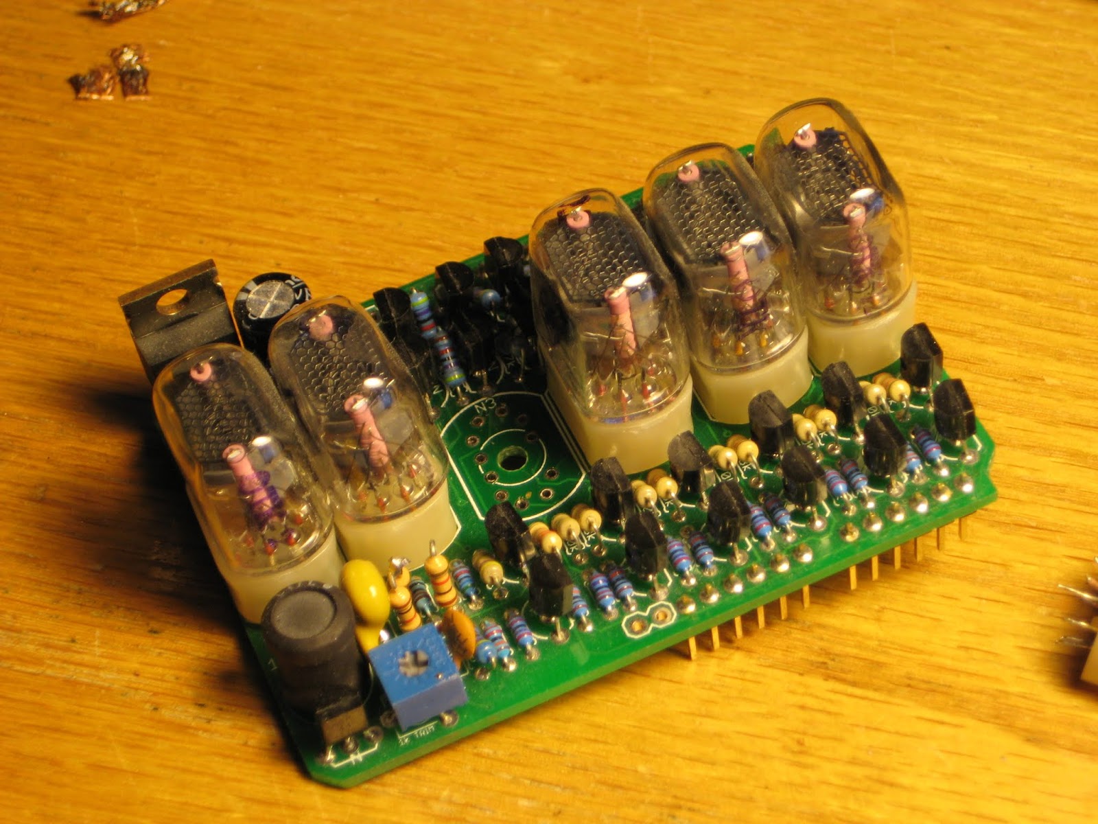
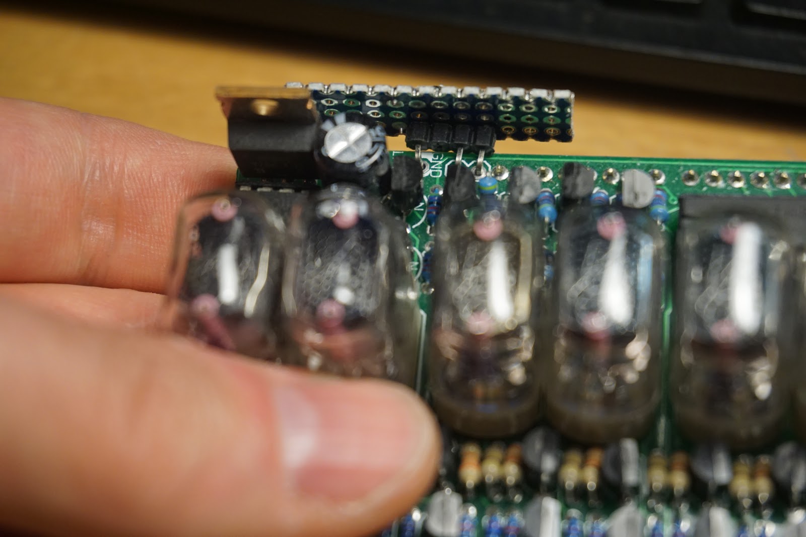
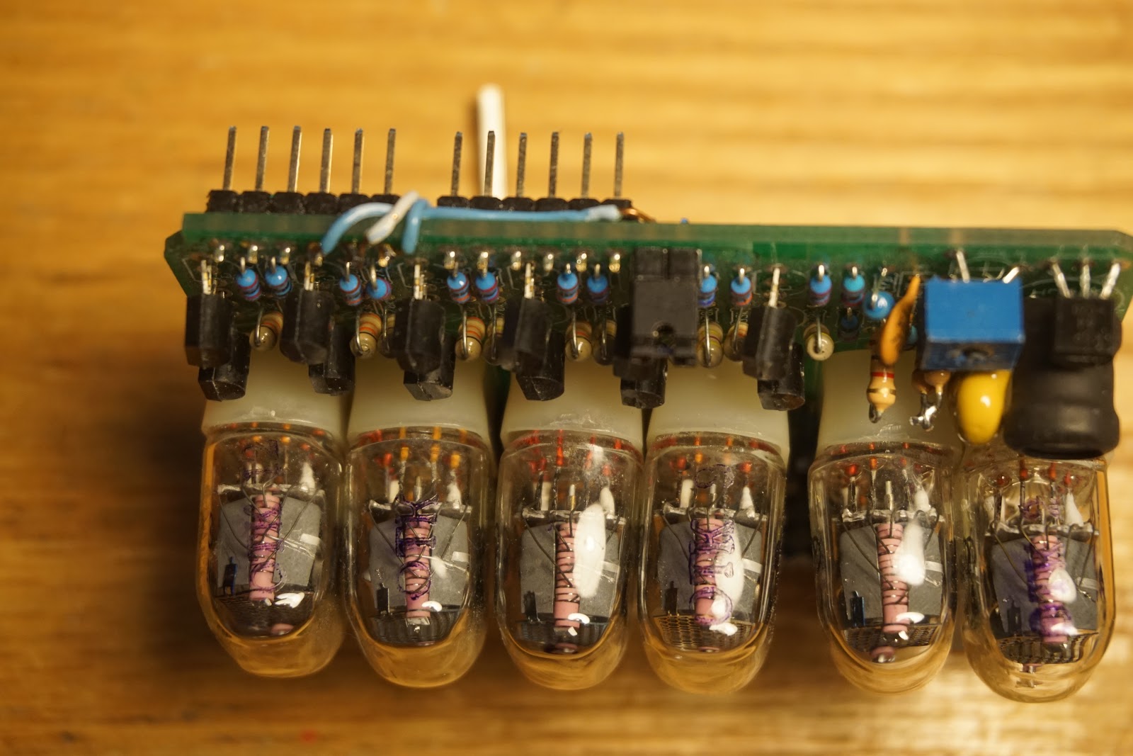
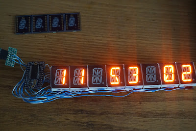
Some time ago, I designed this "4-character 16-segment 1-inch LED" board (pictured below), briefly mentioned here. I abandoned it, after a couple of failed tries, while writing the character definitions. Since then, I discovered the Adafruit 4-char alphanumeric LED backpack, which comes with nice software support as well.


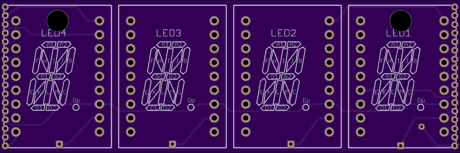
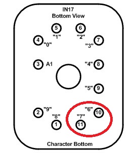
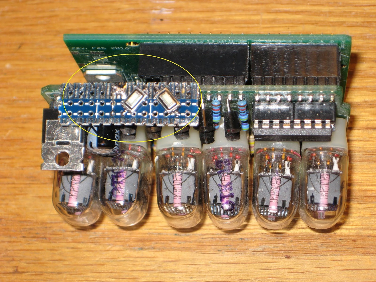
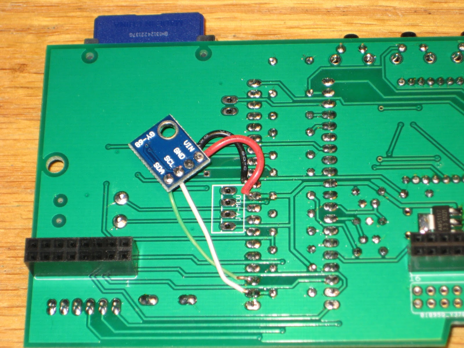
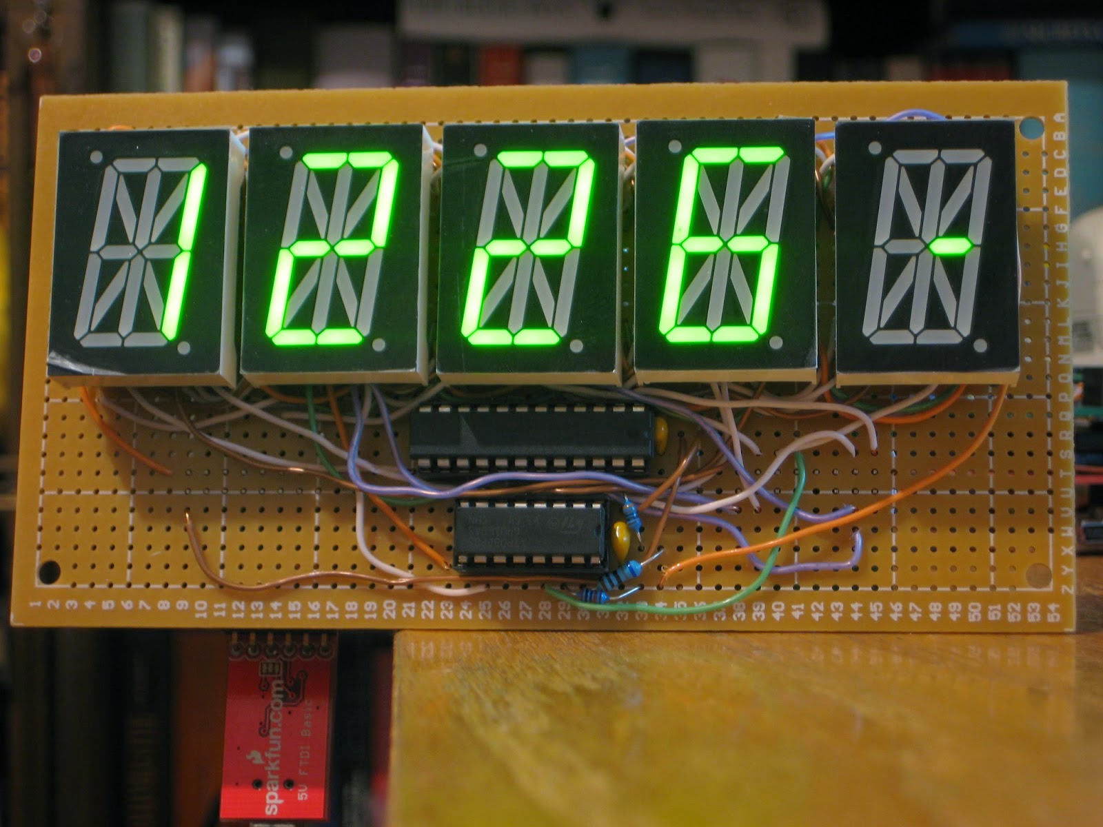
For WiFiChron, two cascaded modules make an 8-character display functionally similar to HDSP-2534, but bigger and more visible. With the "Display Abstraction Layer" already in place, software support should be easy to integrate, since controlling it with the HT16K33 breakout allows the re-use of the above mentioned Adafruit LED backpack library. For maximum compatibility, I followed the same wiring, then connected the two extra segments, A2 and D2, to pin 10 (not connected for the 14-segment backpack) and pin 11 (connected to the DP), respectively.


I added a new class, Alphanum8x16, to the original files (Adafruit_LEDBackpack.h and cpp) to control the extra segments:


class Alphanum8x16 : public Adafruit_AlphaNum4
{
 public:
  void writeDigitAscii(uint8_t n, uint8_t ascii);
};


void Alphanum8x16::writeDigitAscii(uint8_t n, uint8_t a)
{
  uint16_t font = pgm_read_word(alphafonttable+a);
  displaybuffer[n] = font;

  //--------------------------------------------------------
  // this is the Adafruit mapping of digits to segments:
  // 0 DP N M L K J H G2 G1 F E D C B A
  //
  // this is the 16 seg mapping of digits to segments:
  // A2 D2 N M L K J H G2 G1 F E D1 C B A1
  //
  // bits:
  // 1  1  1 ...                 ...  1 0
  // 5  4  3
  //
  // Note: DP is not connected/controlled for the 16 seg;
  //--------------------------------------------------------

  // if A1 (bit 0) is on, set A2 (bit 15) as well;
  if (font & 1)
    displaybuffer[n] |= 0x8000;

  // if D1 (bit 3) is on, set D2 (bit 14) as well;
  if (font & 8)
    displaybuffer[n] |= 0x4000;
}

The 8x16-segment display is implemented in class DisplayHT16K33 in the WiFiChron software.
So far, WiFiChron can support the following displays (defines in DAL.h):

//#define DISPLAY_HDSP2534
//#define DISPLAY_DL1414
#define DISPLAY_HT16K33
//#define DISPLAY_OLED
//#define DISPLAY_HT1632
//#define DISPLAY_MAX6955

In principle, any display that can show 8 characters can be used through DAL.


Wise time with Arduino 14 Apr 02:15
hacking  hdsp  i2c  wifichron  

Debugging the IN-17 Nixie clock (aka "Rothko clock")

This weekend I felt like doing something, which rarely happens lately. From the pile of semi-failed ("started but not finished", "finished but not working", "not fully functional" etc.) I picked the Nixie clock with 6 IN-17 tubes. Its problem was that it did not display any 6 nor 7, on all tubes. A quick check with the meter showed, indeed, a short between 2 neighbor pins. Upon visual inspection (not as easy as it used to be) and with a lot of luck (and magnification), I found the culprit: one tube in the middle of them all had two pins crossed (inverted), as shown in the photo below.


Here is the board with the IN-17 removed.


Since it was impossible for me to re-insert the old short-pined IN-17 (because of the tight space), I had to use a new one. Everything turned out well in the end.

Now onto the usability of this pretty Nixie clock. The only way to set the time is to send commands from a Bluetooth device (phone, tablet). This is not very "user friendly", nor quick, is it? The obvious "remedy" to this situation was to add a couple of buttons on top, where they can be easily pressed. As you may know from my old post, the high voltage (170V) for powering the IN-17 tubes is generated in the same top-of-the-board area, definitely not a good place for fingers. The solution was to use a longer piece of prototyping PCB to cover the danger zone.


As in most simple clocks, the right button increments the minutes, the left one increments the hours, while the seconds are always reset.

I also added a hardware "12 hour mode" through the use of a jumper placed at the bottom of the board:


With the jumper off, the clock shows military time (the hours between 0 and 23).

Unlike the first version, this new Nixie clock, which I shall name "Rothko clock" from now on, uses just 2 boards: wsduino (with on-board RTC and XBee support, assembled for 9V power) and the Nixie shield itself. The 2-button hack should be made somehow permanent, probably by adding them onto the Nixie shield, similar to the LED matrix mini display shield used in the Mondrian clock. Also note that the alarm feature won't work (although implemented in the code, shared here) since there is no buzzer. Bluetooth should still work with a BTBee module plugged into its wsduino socket.

Interestingly, after all these years, one "new old stock" IN-17 Nixie tube can still be bought on ebay for about $7 (compared with about $2 for the bigger IN-12s).

Here are a few more detail photos on the wires that connect the buttons:


The hour buttons (on the left) is connected to A1.
The minutes button (right side) is connected to A0.
The "12/24H mode" header pins (with jumper, at the bottom side of the board) are connected to A2 and GND. Jumper on means pin A2 to the ground, thus enabling 12H mode.


Wise time with Arduino 17 Mar 20:16
hacking  nixie  

Add a barometer sensor to Wise Clock 4

While cleaning up my desk, I found a little I2C module that I completely forgot about. It is a breakout for BMP180 barometer sensor, which I probably bought on ebay for a couple of dollars (I just checked, it is still under $2). This tiny board can be added literally to any Arduino clock to display atmospheric pressure, with the help of Adafruit_BMP085 library.

Connecting the barometer to Wise Clock 4 is trivial: I soldered wires directly to processor pins (SDA, SCL, VCC and GND), as shown in the photo. There is plenty of clearance between the board and the display.


In the software, as mentioned, I used the Adafruit BMP085 library, which also covers the compatible BMP180. There is no extra setting required from the user: the pressure is displayed together with the temperature, and enabled/disabled from the TEMP+/- menus. Also, there is no extra settings when compiling/building: if the BMP180 module is not installed, no pressure data will be displayed.

Essentially, the new code consists of 2 functions added to the AppTmp class:

boolean CAppTmp::initBarometer()
{
  bmp = new Adafruit_BMP085_Unified(10085);
  isBaro = bmp->begin();
}

int CAppTmp::getPressure()
{
  int pressure = 0;
  if (isBaro)
  {
sensors_event_t event;
bmp->getEvent(&event);
    if (event.pressure)
{
  pressure = event.pressure;
}
  }
  return pressure;
}      

Another nice thing about BMP180 is that it can also provide the temperature. But, like DS3231, it seems to be a little off compared with a regular thermometer sitting nearby.

Next, I will try to attached the little barometer to wsduino in an aesthetically pleasing manner, probably in the empty space in the top left corner.

Home-made Wise Clock-based Alpha Clock Five

I saw Justin's recent post on Alpha Clock Five and I just couldn't resist not to try it myself too. Since I didn't have that clock, I thought of improvising one by making a 5-character display that would plug into my Wise Clock 4 board. The idea was easy, the implementation not so. After many hours of hand-wiring, this is how it looks like.


The displays are 1" single digit alphanumeric (common anode) from sparkfun, now retired. They came with non-functional dots, probably the reason they were less than $2 each.
The spacing between the individual displays is forced by the protoboard.


The 2 boards are connected through the pairs of 2x8 headers. All pins used by Alpha Clock 5 to drive the displays are wired to the unused header on the Wise Clock 4 board.


Not to mention  that the software compilation and upload worked without any glitch (after downloading the very nice DS1307RTC library)

The only regret is that this clock lacks seconds. One extra display would have added lots of extra value, but probably lacked the cool factor (the "6-letter clock" requires a lot more memory to store all 6-letter words than the approx 50k required by the 5-letter-word collection).

You should try this at home :)

Using HID Tricks to Drop Malicious Files

[Nikhil] has been experimenting with human interface devices (HID) in relation to security. We’ve seen in the past how HID can be exploited using inexpensive equipment. [Nikhil] has built his own simple device to drop malicious files onto target computers using HID technology.

The system runs on a Teensy 3.0. The Teensy is like a very small version of Arduino that has built-in functionality for emulating human interface devices, such as keyboards. This means that you can trick a computer into believing the Teensy is a keyboard. The computer will treat it as such, and the Teensy can enter keystrokes into the computer as though it were a human typing them. You can see how this might be a security problem.

[Nikhil’s] device uses a very simple trick to install files on a target machine. It simply opens up Powershell and runs a one-liner command. Generally, this commend will create a file based on input received from a web site controlled by the attacker. The script might download a trojan virus, or it might create a shortcut on the user’s desktop which will run a malicious script. The device can also create hot keys that will run a specific script every time the user presses that key.

Protecting from this type off attack can be difficult. Your primary option would be to strictly control USB devices, but this can be difficult to manage, especially in large organizations. Web filtering would also help in this specific case, since the attack relies on downloading files from the web. Your best bet might be to train users to not plug in any old USB device they find lying around. Regardless of the methodology, it’s important to know that this stuff is out there in the wild.


Filed under: Arduino Hacks, security hacks

M4 receiver backpack for reliable wireless remote control

My investigation into the failure of the M4 receiver remote controlling my Wise Clock 4 concluded with the need to add a step-up converter. The Sure 1632 display makes the input voltage drop sometimes below the absolute minimum of 4.5V required for the M4 module to work properly. It's not the noise (spikes) in the 5V power, nor the interference on 315MHz.

I designed a simple "M4 receiver backpack" that uses a DC-DC step-up converter to ensure a 5V power for the M4 receiver module. The board supports 2 different kinds of converters, one from ebay (red in the photo below), the other from tindie (made by BBtech, black in the photo).


The backpack can be used, by default, without the step-up converter if the voltage is steady at around 5V. (A trace-jumper must be cut when a converter is added.)

The wireless remote pair of 4-key fob transmitter and receiver module is sold by Adafruit or vendors on ebay.

The assembled board wired to Wise Clock 4 is shown in the photos below. Note that only 3 out of 4 buttons on the remote have a function on the clock. Each button press could light up a (optional) LED on the receiver board for visual confirmation.


A new design of the Wise Clock 4 board should probably feature a header for plugging in the receiver module, otherwise the back of the board will show a bunch of ugly wires.


This M4 receiver backpack could be used for adding remote control to other devices with buttons, especially when these buttons are hard to access (due to enclosure design constraints), or hidden (for aesthetic purpose). One example that comes to mind is an oscilloscope clock fully enclosed in transparent acrylic; drilling holes for the buttons would require some design stretches.

The M4 receiver backpack would be also suitable for hacking an old alarm clock. Please let me know if anyone is interested :)

A garment transporter made with Arduino Robot

Last March  RS Components, in collaboration with RobotChallenge, launched the Hack the Arduino Robot competition.

Jacob Glueck submitted a great hack for the Arduino Robot:

“A couple of years ago, I built an Arduino-powered shirt-folding machine which folds clothes. Using the Arduino robot from the RobotChallenge, I will build a device to remove folded clothes from the machine and to stack them. My idea is special because it will involve two Arduinos (the Arduino Uno in the shirt folder, and the Arduino Robot) which will have to communicate, and because it will be very useful. The robot will solve the real life problem of laundry folding by making the task easier and faster and by doing so nicely; the robot will use a custom-designed gripper to transport garments while keeping them perfectly folded.”

On his blog you can look at the pictures of the construction  phase , and below watch the video of the final project:

Arduino Blog 10 Jun 20:31

Flutter: A $20 wireless Arduino with a long reach

If the words "ARM-powered wireless Arduino" send your heart aflutter, then you might be interested in... Flutter -- a development platform with the aforementioned qualities. The Kickstarter project claims the device has a usable range of over half a mile, letting you nail that wireless letterbox-checker project with ease. Similar tools, such as Xbee and Zigbee already exist, but the $20 price tag for the Flutter basic, and $30 for Flutter Pro (adds battery charging, another button, more memory) make this a tempting option for tinkerers on a budget. So, if building that mesh network of quadrocopters has been sitting at the top of your to-do list for too long, we recommend you get backing right now.

Filed under: Networking, Internet

Comments

Via: Ycombinator

Source: Kickstarter

Engadget 28 Aug 13:17

Arduino-compatible VFD modular clock from Akafugu

There aren't many VFD clock kits out there that are software-compatible with Arduino (and by that I mean the "Arduino sketch" being compilable in Arduino IDE and uploadable through USB-FTDI).
Most of these kits come with the microcontroller pre-programmed, so they can be built quickly and easily, with minimal effort (totally understandable instant gratification; nobody wants to end up with an expensive dud). Upgrading the software usually requires familiarity with the microcontroller toolchain (compile-build-flash), plus an ISP programmer. (Note: The only processor I am familiar with is AVR/Atmega.)

I was going to build myself an Arduino-based VFD clock, one that can take a sketch through the FTDI cable. Instead of starting from scratch (choosing a schematic, making the board etc), I decided to try one of the only 2 open-source VFD clock kits I found that are based on Atmega processor and :

I settled for the VFD modular clock because the Akafugu people offered me the pair of PCBs in their kit (for a very reasonable $19, shipping included) and also because I already had most of the parts, including the two SMDs (that come pre-soldered in the kit: ATmega328 and HV5812) and the IV-17 VFD tubes.


I built the clock following their great assembling instructions, but, as you will see, not without hitting a few stumbling blocks on the way.

I should clarify that this post is not a review of the VFD modular clock kit (since I did not have the kit), but just a record of my observations. It was my choice to not use the kit, thus forcing myself to try to understand the schematic and the software.

Since my goal was to make the VFD modular clock Arduino-compatible, I was aware of the challenges awaiting me:
- burning the bootloader for ATmega328 with internal 8MHz oscillator;
- connecting a makeshift FTDI header;
- adapting the software to work in Arduino IDE;

Once I figured out the fuses, burning the bootloader was straightforward. For this purpose I created this section in boards.txt:

intclock328.name= ATmega328 Internal clock 8MHz
intclock328.upload.protocol=stk500
intclock328.upload.maximum_size=30720
intclock328.upload.speed=57600
intclock328.bootloader.low_fuses=0xE2
intclock328.bootloader.high_fuses=0xDA
intclock328.bootloader.extended_fuses=0x05
intclock328.bootloader.path=atmega
intclock328.bootloader.file=ATmegaBOOT_168_atmega328_pro_8MHz.hex
intclock328.bootloader.unlock_bits=0x3F
intclock328.bootloader.lock_bits=0x0F
intclock328.build.mcu=atmega328p
intclock328.build.f_cpu=8000000L
intclock328.build.core=arduino

Then I checked that the bootloader works, by uploading a simple sketch that outputs on D9 (which is connected to the buzzer). Before doing this, I had to connect the FTDI breakout to the board. Luckily (more probably intentionally), all of the required pins (Rx, Tx, Vcc, Gnd, Rst) are broken out on the female header, so just using wires worked, as shown in the next photo. This is not a nice solution though, since the top board (with the VFDs) needs to be removed before every sketch upload. (Hopefully the Akafugu team will also include an FTDI header in the next revision.)


After I soldered all the parts on the base board, I realized the biggest problem of them all: some parts (sourced by me, and obviously of different size than those in the kit) stuck well above the two lateral headers, so the display shield (upper board) could not be plugged in the base board. Almost a showstopper at this point. The solution was to replace the tall 330uF/16V capacitor, bend both 47uF capacitors sideways, replace the 330uF/50V with a pair of thinner 100uF, push both inductors as much into the PCB as possible, then cut the top plastic wrapping on one of them. These, combined with the male headers not being flush to the display board when I soldered them, did the trick. I managed to have the clock looking as intended by its creators (if you don't look too closely), as shown in the next photo.


The Akafugu designers tried to minimize the size of the clock, leaving little room for flexibility (that is, ability to use a broader range of components, of different sizes eventually). The sizes for the chosen components (especially the capacitors and the inductors) are really unique, any deviation would lead to the boards not fitting together.
Using (smaller) SMD components would not be a good solution, since these would also need to be pre-soldered (or otherwise potential non-SMD-soldering clients would be excluded). The only compromise I can think of is enlarging the base board a little bit, keeping in mind that this 4-tube version is the smallest of the display boards, all others extending laterally beyond both sides of the base board.

And finally, the last challenge: the software. I started from the original C code published here. This was written for the avr-gcc compiler and produces a hex file, which is then flashed onto the processor (no bootloader needed, nor provided) using an ISP programmer.

I changed the code (available here), mostly cosmetically, to compile with Arduino 1.0. It does not require any other external libraries and it includes its own I2C/Wire functions (does not use Arduino's Wire library).

In the end, I have an Arduino-compatible Akafugu VFD modular clock that looks just like the original one (I need to add the spacers though).


Wise time with Arduino 21 Jun 04:39
general  hacking  nixie  review  

Hamburg Maker Meeting 2012 and Arduino Due preview

Hamburg Maker Meeting 2012, which took place last week and involved about 200 visitors and more than 20 exhibitors, has been a fantastic opportunity to meet and share experience regarding several topics, such as 3D printing, hacking, retro gaming and so on. At the Attraktor Makerspace, several projects have been presented and demonstrated by their inventors, among which we highlight a very nice Arduino-based floppy drive organ that has been employed to play the Tetris game theme.

Moreover, among the others events planned for the meeting, a special sneak-preview session allowed all the interested people to get some insights on the new Arduino Due board, released a couple of days ago.

A video of the event can be found here, while here you may find more pictures.

More information can be found on the homepage of the meeting.

[Via: Hamburg Maker Meeting website]