Posts with «fan» label

Controlling the heater and fan

Here is the circuit for the heater and fan that I’ve been developing for incubator project for the freshman design course:

Here is the circuit I’ve been using for playing with control loops. (The 74HC14N Schmitt trigger inverter does not have an enable input, but SchemeIt has a very limited and idiosyncratic set of schematic symbols, so I used the closest one.)

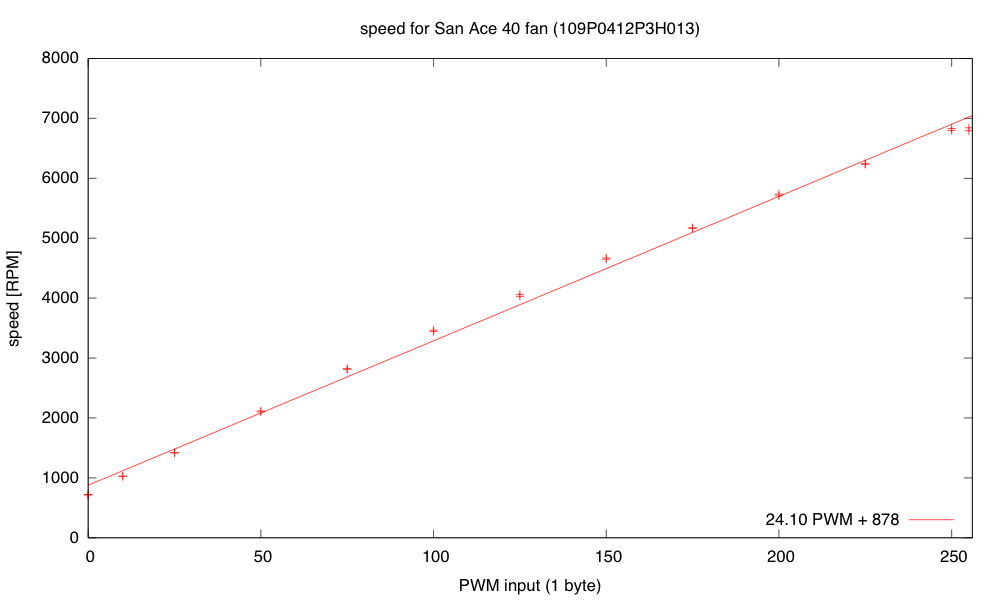
Yesterday and this morning, when I was developing the controller software for the fan and resistive heater, I ran into a lot of problems with overshoot when changing the setpoints. For the fan controller I wrote One thing that helped was not accumulating integral error when the PWM signal was pinned at the lowest or highest values.”  I also switched to using RPM rather than pulse duration as the measured variable, because RPM is nearly linear with the PWM input (RPM approximately 24.1 PWM + 878). Another thing “that helped was to make a guess at the target PWM setting when the setpoint was changed (using d RPM/ d PWM =24 and the current PWM setting and RPM value), then setting the cumulative error to what it would be in steady state at that PWM. I then set the PWM to five times as far from current PWM as the target PWM to make the transition as fast as possible without increasing overshoot, making sure to clip to the legal 0..255 range.”  Because I have a reasonable model for RPM as a function of PWM, it was easy to estimate what the target PWM should be so that the cumulative error from the integrator would set the PWM value correctly once the error dropped enough that the desired PWM value was no longer pinned at the limits.

Today I decided to do a little reading to find out what other people have done about the problem of the controller overshooting when the actuator hits its limits.  It turns out that the phenomenon is know as “integrator windup“, and the two solutions I came up with are standard solutions.  Turning off the error accumulation when the actuator is at its limit and more movement in that direction is desired is known as “conditional integration” and guessing the correct setting for the cumulative error on setpoint change is a form of “back calculation”.  There are more sophisticated forms of back calculation that I might want to try implementing.  (I found a better explanation of the anti-windup scheme, which I might base my next implementation on—basically it gradually reduces the cumulative error to 0 as long as the desired setting for the actuator is past its limits.)

The temperature controller has been harder for me to tune, for several reasons:

  • The response time is very long.  Instead of oscillating around 5Hz, the period seems to be more like 90 seconds.  This means that it takes a long time to see whether an adjustment to the parameters makes a difference.
  • The temperature at the thermistor is dependent on the temperature at the resistor.  The thermal mass and thermal resistance act like an RC circuit (with temperature analogous to voltage, and power dissipated analogous to current).  Adjusting the power to the resistor via PWM changes the rate at which the temperature increases.  It also changes the eventual equilibrium temperature, but the PWM control is more directly of the rate of temperature change.
  • The heatsink and resistor continue to warm the air and the measuring thermistor even after all power to the resistor is cut off, so there is a big danger of overshoot whenever the setpoint temperature is increased.
  • The control is asymmetric—dumping 40W of power into the resistor heats it up fairly fast, but heat is only slowly dissipated when power is turned off.  Running the fan fast helps a little here, slowing down the temperature rise and speeding up the cool down, but once I put the whole thing in a closed box, it will be very difficult to cool things off if the box gets too warm.  This makes overshoot in the positive direction  a serious problem.
  • The temperature measurements are only about 0.1°C resolution, and the noise on the ADC is about ±4LSB, so it will be difficult to get tight temperature control, even with a perfectly tuned controller.
  • I don’t have a simple model of what the steady-state thermistor temperature will be given the PWM input, so I’ve had difficulty coming up with a guess about the eventual PWM value for resetting the cumulative error on a setpoint change.  I have a model for the resistor temperature in still air, but the fan makes a huge difference, both in the thermal resistance (and so both the equilibrium temperature and time constant of the resistor heating) and in the coupling between the resistor and the thermistor.

I still have a lot of things left over from a couple of days ago, and I’ve added some new things to the list.

  • Put the whole thing into a styrofoam box, to see whether extra venting is needed to allow things to cool down, and to see how tightly temperature can be controlled. I’ve put stuff in the box, but I can’t close the box with the stuff sticking out, so it doesn’t really count.
  • Design and build baffling for the fan to get better airflow in the box. I’ve made a little paper and wire baffle, to get better air flow over the resistor, but I’ve not done the full baffling to get good airflow in the box.
  • Figure out how to get students to come up with workable designs, when they are starting from knowing nothing. I don’t want to give them my designs, but I want to help them find doable subproblems.  Some of the subproblems they come up with may be well beyond the skills that they can pick up in the time frame of the course. The more I work on this project, the more I realize that I and the students will have to be happy with them having explored the options, without getting all the problems solved.
  • Find a smaller bread board or prototype board to put the controller on—my current bread boards are all 6.5″ long, and the box only has room for 6″, especially since I put the resistor in the center of the 6″×12″ aluminum plate, which just fits the box.  I suppose I could drill a couple more holes in the plate and mount the resistor off center, but I rather like the idea of building the controller as an Arduino shield, so that the Arduino + controller is a single unit.
  • Another possibility is to drill a hole in the styrofoam box and run cables through the box for the resistive heater, the fan, and the thermistor.  Even if the grounds are connected outside the box, this is only 8 wires. Putting the control electronics outside the box would reduce the clutter in the box and make tweaking easier.
  • Add some low-pass filtering to the temperature measurement to reduce noise.  Just adding 4 measurements in quick succession would reduce the noise and give the illusion of extra precision.
  • The fan controller occasionally has a little glitch where the tachometer either misses a pulse or provides an extra one (I think mainly an extra one due to ringing on the opposite edge).  I could try reducing this problem in three ways: 1) changing which edge I’m triggering on, 2) using more low-pass filtering before the Schmitt trigger in the edge detector, or 3) using median filtering to throw out any half-length or double-length pulses, unless they occur as a pair.  (Hmm, the half-length pulses would occur as a pair, so this might not help unless I go to median of 5, which would be a lot of trouble.)
  • Improve my modeling of the thermal system, so that I can do more reasonable back calculation on setpoint change.
  • Consider using a PID controller for the temperature to get faster response without overshoot.  (If I can reduce the noise problem.)
  • Improve my anti-windup methods for both thermal and fan controllers, to reduce overshoot.

Filed under: freshman design seminar Tagged: Arduino, control loop, fan, incubator, integrator windup, PID controller, power resistor, PWM, tachometer, thermistor

PWM heater and fan continued

Yesterday I gave myself the following to-do list:

  • Check the VDS voltage at 4A on the nFET. Is the on-resistance still much too high?

    Yes, with the 1.8Ω resistor I get 110mV across the FET with 8.372V across the resistor, so at 4.65A I’m seeing an on-resistance of 24mΩ, still much higher than the 10mΩ I was expecting, but closer than I was getting yesterday at 1A. The voltage across the nFET does go up as the nFET warms up, but the nFET does not get too hot (up to around 45°C).

  • Try adding a 1kΩ gate resistance to slow down the transitions on the PWM, to see if that reduces the inductive spikes and the noise-coupling through the 9V power supply.

    Slowing the transitions definitely reduced the spikes, from about 13V to about 1V.  The bypass capacitors absorbed the highest-frequency spikes, and the 470µF polymer electrolytic capacitor seems to be enough—the 10µF ceramic doesn’t seem to add any extra suppression.  At about 94% duty cycle the noise on the power supply is about the following:

    gate resistor bypass capacitor peak-to-peak noise
     0Ω  none  20V
     1kΩ  none  3V
     0Ω  10µF  2.5V
     1kΩ  10µF  2.5V
     0Ω  470µF  1V
     1kΩ  470µF  0.3V

    The slew rate for the drain voltage with the 1kΩ gate resistor is about +7V/µs and -5V/µs.

  • Write a simple control loop for the fan speed, so that the fan speed can be held constant even when the power-supply voltage changes.  This may be an opportunity to try the P/PI/PID tuning, since the control loop should be fairly fast.

    I wrote a simple PID controller with the control variable being the fan PWM and the measured variable being the time per pulse (in µsec).  I tried tuning the controller by adjusting the proportional gain until the control loop barely oscillated, then cutting the gain to 0.45 of that and setting the integration time to about period of the oscillation (very loosely estimated).  I then tweaked the parameters until it seemed to give good control without oscillation over the full range of fan speeds.I tried the differential control, but the noisiness of the speed measurement (which I was not filtering at all) makes the derivative far too touchy, even with tiny amounts of differential control, so I used a simple PI controller instead.  I don’t think that the optimal parameters are the same at the high speed and low speed for the fan, but it was not difficult to find parameters that worked fairly well across the range.  One thing that help was not accumulating integral error when the PWM signal was pinned at the lowest or highest values.

    The speed is almost linear with the PWM input, so I would probably get better control if I used speed (the reciprocal of the pulse duration) as the measured value in the controller.

    The fan speed is nearly linear with PWM, which is ideal for proportional control, but I had foolishly used the pulse duration as my measured value to control.

    I rewrote the controller as a simple PI controller, using 16*RPM as my measured variable, so that I could have an integer setpoint with sufficient resolution. I’m still using floating-point in the controller for simplicity of coding but I plan to switch to fixed-point soon. This controller was fairly easy to tune—I made the Kplarge enough that system oscillated, and counted how many samples were in the period, then set the integration time to about the period. I then reduced Kp until the oscillations went away. I ended up with Kp = 0.01 PWM/16RPM and TI= 1/0.15 samples (with a sampling rate of 30ms, so TI=0.2s).

    One thing that helped was to make a guess at the target PWM setting when the setpoint was changed (using d RPM/ d PWM =24 and the current PWM setting and RPM value), then setting the cumulative error to what it would be in steady state at that PWM. I then set the PWM to five times as far from current PWM as the target PWM to make the transition as fast as possible without increasing overshoot, making sure to clip to the legal 0..255 range.

  • Write a simple control loop for controlling the temperature at the thermistor, by adjusting the PWM for the resistor.  This might get messy, as the fan speed probably affects the rate of transfer from the resistor to the thermistor (the thermistor is in the air stream blown over the resistor, not touching the resistor).

    When I started working on this, my power supply failed. I’m afraid it might have shorted when I was rewiring things (though I never saw evidence for a short). I’ll leave it overnight (in case there is a resettable poly fuse) and check it in the morning. If there is still no power, I’ll open the case and see if there is a replaceable fuse inside. I’m afraid that this may have a soldered-in non-resettable fuse, which would be a terrible design—setting me back a couple of weeks as I either order a replacement fuse or a replacement power supply.

    Correction: the power supply was fine—I’d managed to blow a circuit breaker for the room. I’m not sure how I did that, but resetting the circuit breaker fixed the problem. I now have a temperature control sort of working—I still have to tune the control loop, but I was able to get the thermistor to about 30°C (400 as the Arduino reading) and hold it to within about 0.3°C. There was a pretty substantial overshoot at the beginning, which I’ll have to look into controlling—the temperature controller may need to be critically damped. Now it really is time for me to get some sleep.

  • Put the whole thing into a styrofoam box, to see whether extra venting is needed to allow things to cool down, and to see how tightly temperature can be controlled.
  • Design and build baffling for the fan to get better airflow in the box.
  • Figure out how to get students to come up with workable designs, when they are starting from knowing nothing. I don’t want to give them my designs, but I want to help them find doable subproblems.  Some of the subproblems they come up with may be well beyond the skills that they can pick up in the time frame of the course.

Filed under: freshman design seminar Tagged: Arduino, fan, incubator, power resistor, PWM, tachometer, thermistor
PWM heater and fan continued

Yesterday I gave myself the following to-do list:

  • Check the VDS voltage at 4A on the nFET. Is the on-resistance still much too high?

    Yes, with the 1.8Ω resistor I get 110mV across the FET with 8.372V across the resistor, so at 4.65A I’m seeing an on-resistance of 24mΩ, still much higher than the 10mΩ I was expecting, but closer than I was getting yesterday at 1A. The voltage across the nFET does go up as the nFET warms up, but the nFET does not get too hot (up to around 45°C).

  • Try adding a 1kΩ gate resistance to slow down the transitions on the PWM, to see if that reduces the inductive spikes and the noise-coupling through the 9V power supply.

    Slowing the transitions definitely reduced the spikes, from about 13V to about 1V.  The bypass capacitors absorbed the highest-frequency spikes, and the 470µF polymer electrolytic capacitor seems to be enough—the 10µF ceramic doesn’t seem to add any extra suppression.  At about 94% duty cycle the noise on the power supply is about the following:

    gate resistor bypass capacitor peak-to-peak noise
     0Ω  none  20V
     1kΩ  none  3V
     0Ω  10µF  2.5V
     1kΩ  10µF  2.5V
     0Ω  470µF  1V
     1kΩ  470µF  0.3V

    The slew rate for the drain voltage with the 1kΩ gate resistor is about +7V/µs and -5V/µs.

  • Write a simple control loop for the fan speed, so that the fan speed can be held constant even when the power-supply voltage changes.  This may be an opportunity to try the P/PI/PID tuning, since the control loop should be fairly fast.

    I wrote a simple PID controller with the control variable being the fan PWM and the measured variable being the time per pulse (in µsec).  I tried tuning the controller by adjusting the proportional gain until the control loop barely oscillated, then cutting the gain to 0.45 of that and setting the integration time to about period of the oscillation (very loosely estimated).  I then tweaked the parameters until it seemed to give good control without oscillation over the full range of fan speeds.I tried the differential control, but the noisiness of the speed measurement (which I was not filtering at all) makes the derivative far too touchy, even with tiny amounts of differential control, so I used a simple PI controller instead.  I don’t think that the optimal parameters are the same at the high speed and low speed for the fan, but it was not difficult to find parameters that worked fairly well across the range.  One thing that help was not accumulating integral error when the PWM signal was pinned at the lowest or highest values.

    The speed is almost linear with the PWM input, so I would probably get better control if I used speed (the reciprocal of the pulse duration) as the measured value in the controller.

    The fan speed is nearly linear with PWM, which is ideal for proportional control, but I had foolishly used the pulse duration as my measured value to control.

    I rewrote the controller as a simple PI controller, using 16*RPM as my measured variable, so that I could have an integer setpoint with sufficient resolution. I’m still using floating-point in the controller for simplicity of coding but I plan to switch to fixed-point soon. This controller was fairly easy to tune—I made the Kplarge enough that system oscillated, and counted how many samples were in the period, then set the integration time to about the period. I then reduced Kp until the oscillations went away. I ended up with Kp = 0.01 PWM/16RPM and TI= 1/0.15 samples (with a sampling rate of 30ms, so TI=0.2s).

    One thing that helped was to make a guess at the target PWM setting when the setpoint was changed (using d RPM/ d PWM =24 and the current PWM setting and RPM value), then setting the cumulative error to what it would be in steady state at that PWM. I then set the PWM to five times as far from current PWM as the target PWM to make the transition as fast as possible without increasing overshoot, making sure to clip to the legal 0..255 range.

  • Write a simple control loop for controlling the temperature at the thermistor, by adjusting the PWM for the resistor.  This might get messy, as the fan speed probably affects the rate of transfer from the resistor to the thermistor (the thermistor is in the air stream blown over the resistor, not touching the resistor).

    When I started working on this, my power supply failed. I’m afraid it might have shorted when I was rewiring things (though I never saw evidence for a short). I’ll leave it overnight (in case there is a resettable poly fuse) and check it in the morning. If there is still no power, I’ll open the case and see if there is a replaceable fuse inside. I’m afraid that this may have a soldered-in non-resettable fuse, which would be a terrible design—setting me back a couple of weeks as I either order a replacement fuse or a replacement power supply.

  • Put the whole thing into a styrofoam box, to see whether extra venting is needed to allow things to cool down, and to see how tightly temperature can be controlled.
  • Design and build baffling for the fan to get better airflow in the box.
  • Figure out how to get students to come up with workable designs, when they are starting from knowing nothing. I don’t want to give them my designs, but I want to help them find doable subproblems.  Some of the subproblems they come up with may be well beyond the skills that they can pick up in the time frame of the course.

Filed under: freshman design seminar Tagged: Arduino, fan, incubator, KL25Z, power resistor, PWM, tachometer, Teensy, thermistor

PWM heater and fan

Now that I have a power resistor and heatsink, and have verified that my power supply is capable of delivering 50W, I can try making a thermal control system for an incubator box as I hope to get the freshman design class to do.

Before building a complete control system and tuning a proportional, PI, or PID controller, I decided to check each of the components:

  • 1.8Ω resistor and heatsink (already characterized in still air in the previous post). Initially I was going to use the 8.2Ω resistor, but it heated so slowly once bolted to the heatsink that I wasn’t sure that students would have the patience to wait for it—they might conclude that things weren’t working.
  • NTD4858N-35G nFET for PWM control of the heater.
  • fan.  I bought a SanAce 40 109P0412P3H013 fan with PWM control and tachometer feedback, and I wanted to be sure that I could control the fan speed and read the tachometer.
  • thermistor. I had some NTCLE100E3103JB0 thermistors around that I had never used.  They’re not ideal for measuring temperature of resistors (they only go up to 125°C), but they should be find for measuring air temperature around 35°C, which is what the incubator will mainly be used at.
  • Arduino board (actually a SparkFun RedBoard, which is plug-compatible with the Uno R3, but has has a more reliable USB interface and is slightly cheaper.

I started out hooking up the nFET and the 1.8Ω resistor and making sure that the nFET did not get too hot.  It seems to be ok.  When I was using the 8.2Ω resistor, I measured the voltage drop across the resistor and the across the nFET, getting a 57.6mV drop from drain to source, with a current of about 9.024V/8.21ohm = 1.099A.  That’s about a 52mΩ on-resistance, and I was expecting more like 7mΩ–10mΩ.  My gate voltage was around 5V (bigger than the 4.5V of the data sheet), which should have given me lower on-resistance.  The only things I can think of are that I had more wiring resistance than I realized (quite likely, but not likely enough to add over 40mΩ), and that I was measuring around 1A, not around 10A, so perhaps there is a small-voltage effect that I don’t know about.

I should probably test the voltage drop again with 1.8Ω resistor, and see whether the on-resistance is still so high.  Better probe placement may get me more accurate voltage measurements also.

The fan runs fine at 9.212V at about 6850 RPM.  Setting the PWM input line of the fan to 0 drops the speed to about 710RPM, and setting the PWM duty cycle to a half sets the speed at about 4120RPM.  The fan is a bit noisy for such a tiny fan at the highest speed setting, but reasonably quiet at lower speeds.  I suspect that bolting the fan to a piece of masonite as a baffle would reduce the fan noise, as I think quite a bit of it was from vibration between the case of the fan and the metal plate it was sitting on.

The tachometer on the fan provides an open-collector output that I read with an interrupt input on the Arduino (pin 2, interrupt 0). I recorded the time between interrupts and converted it an RPM measurement.  The tachometer worked fine when I was just using the fan, or when the resistor was either completely off or completely on, but when I tried using PWM on the resistor, the tachometer readings became nonsense.

I looked at the tachometer signal with my oscilloscope and saw that the PWM transitions for the resistor resulted in huge spikes in the tachometer output that triggered extraneous interrupts.  I suspected noise coupled through the power supply. Adding a 10µF bypass capacitor to the 9V power supply to the fan reduced the problem considerably, and a 470µF aluminum polymer electrolytic cleaned up the power supply even more.  The 10µF alone was enough to eliminate the extraneous spikes in the middle.

I think that I should try adding some gate resistance to the nFET to slow down the rise and fall of the PWM signal a little, to reduce the inductive spikes and make the bypass capacitors more effective.

I noticed that I was still getting some readings that were half the duration that I was expecting.  These could have been caused by ringing at the other transition of the tachometer pulse, so I tried eliminating the ringing by adding some capacitance to the line and changing the pullup resistor.  These attempts were not very successful, so I decided that hysteresis was needed.  I put a Schmitt trigger between the open-collector output and the Arduino interrupt input, and the signal got a lot cleaner.  There were occasional double pulses at one edge, though, but I found that adding a 1nF to 10nF capacitor in parallel with the pullup resistor for the open collector output smoothed out the high frequency noise enough to get clean, single transitions out of the Schmitt trigger.

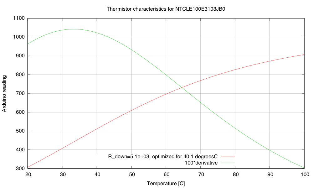
I hooked up the thermistor in a voltage divider with 5.1kΩ on the other leg (which maximizes the dV/dT sensitivity at 40.1°C). I used the parameters on the data sheet to plot a calibration curve for the thermistor:

Calibration and sensitivity curves for the thermistor, based on the data sheet and a 5.1kΩ pulldown resistor.

The maximum sensitivity of the thermistor circuit is around 33.3 degrees C (~10.4 Arduino LSB/°C).  That’s not a very high sensitivity, particularly given the noise of the ADC.  Note that maximizing the slope at 40.1 °C is not the same thing and having the maximum of the slope at 40.1°C.  If the maximum of the slope was at 40.1°C, the slope there would be less than it is in this plot.

My son wonders why I’m using the Arduino board for this project, rather than the FRDM-KL25Z board that I use for the circuits class or the Teensy 3.1 ARM development board. The ARM processors have more power, more memory, and much better analog-to-digital converters—and the KL25Z board is cheaper.  If I were doing this project for myself, I would certainly prefer the KL25Z board. But it is a little harder to get a beginner started on that board—just getting the first program onto the board is a pain if you don’t have a Windows machine (due to the broken bootloader the P&E Micro wrote).  There are instructions now for replacing the firmware from a Linux system, but I’ve not checked yet whether these instructions work from a Mac.  Even once you get working firmware onto the boards, the development environments are not beginner-friendly.  Well, that is certainly true of the MBED environment or bare-metal ARM environment for the KL25Z boards, but the Teensy 3.1 board supposedly can be programmed from a plugin for the Arduino IDE, which might be simple enough for beginners.  This is something for me to look into more.

Of course, one reason I’m using the Arduino Uno or Sparkfun RedBoard is that they are 5V processors, and most of the power nFETs I’ve looked at need 4.5V on the gate to turn on fully.  There are power nFETs now with lower gate voltages, but most of them are only available as surface-mount devices.  I don’t want to have to add an extra transistor or buffer chip as a level changer for the PWM circuit.

The problem is that these students will be brand new to programming, brand new to electronics, and brand new to engineering—and the course is only a 2-unit course, not a full 5-unit course, so the total time students are expected to spend on the course is only 60 hours. I want them to be able to design stuff quickly, without spending all their time learning to use tools or trying to find workarounds for limitations of the devices they are using. It already bothers me that they’ll probably need to use a Schmitt trigger to clean up the tachometer input, but at least hysteresis was a topic I was planning to cover! (The need for bypass capacitors bothers me less—they are so ubiquitous in electronics that I’ll have to cover them no matter what.)

It’s after midnight now, so I’m going to call it a day.  Here is my to-do list on this project:

  • Check the VDS voltage at 4A on the nFET. Is the on-resistance still much too high?
  • Try adding a 1kΩ gate resistance to slow down the transitions on the PWM, to see if that reduces the inductive spikes and the noise-coupling through the 9V power supply.
  • Write a simple control loop for the fan speed, so that the fan speed can be held constant even when the power-supply voltage changes.  This may be an opportunity to try the P/PI/PID tuning, since the control loop should be fairly fast.
  • Write a simple control loop for controlling the temperature at the thermistor, by adjusting the PWM for the resistor.  This might get messy, as the fan speed probably affects the rate of transfer from the resistor to the thermistor (the thermistor is in the air stream blown over the resistor, not touching the resistor).
  • Put the whole thing into a styrofoam box, to see whether extra venting is needed to allow things to cool down, and to see how tightly temperature can be controlled.
  • Design and build baffling for the fan to get better airflow in the box.
  • Figure out how to get students to come up with workable designs, when they are starting from knowing nothing. I don’t want to give them my designs, but I want to help them find doable subproblems.  Some of the subproblems they come up with may be well beyond the skills that they can pick up in the time frame of the course.


Filed under: freshman design seminar Tagged: Arduino, fan, incubator, KL25Z, power resistor, PWM, tachometer, Teensy, thermistor

433 MHz RF module with Arduino Tutorial 3


There are 4 parts to this tutorial:
To get the most out of this tutorial - it is best to start at tutorial Part 1, and then progress to Part 2 then Part 3 and then do Part 4 last. Doing the RF tutorials in this order will help you to understand the process better.


Project 3: RF Remote Control Emulation

In the first tutorial, I introduced the 433 MHz Transmitter and Receiver with a simple sketch to test their functionality. In the second tutorial, the 433MHz receiver was used to receive a signal from an RF remote. The RF remote signal was coded based on the pattern and length of its HIGH and LOW signals. The signals received by the remote can be described by the code below:

 
Code comparison table


The RF remote that I am using transmits the same signal 6 times in a row. The signal to turn the light on is different from that used to turn the light off. In tutorial 2, we were able to "listen to" or receive the signal from the RF remote using the RF receiver. I thought it would be possible to just play back the signal received on the Arduino's analogPin, but the time it takes to perform a digital write is different to the time it takes to do an AnalogRead. Therefore it won't work. You need to slow down the digitalWrite speed.
I would like to find out if it is possible to apply this delay to all 433 MHz signal projects, however, I only have one 433 MHz remote.

If the delay in your project is the same as mine (or different) I would be keen to know - please leave a comment at the end of the tutorial.

We are going to use trial and error to find the optimal digitalWrite delay time. We will do this by slowly incrementing the delay until the transmission is successful. The transmission is considered successful if the fan-light turns on/off. All we have to do is count the number of transmissions until it is successful, then we should be able to calculate the delay.


Parts Required


The Transmitter Fritzing Sketch


RF Calibration - Arduino Sketch


I used an array to hold the RF code for light ON and light OFF. Each number within the code represents a specific sequence of HIGH and LOW lengths. For example, 2 represents a SHORT HIGH and a LONG LOW combination. A short length = 3, a long length = 7, and a very long length = 92. You need to multiply this by the timeDelay variable to identify how much time to transmit the HIGH and LOW signals for.
The short and long lengths were identified from the experiments performed in tutorial 2 (using the RF receiver). Each code is transmitted 6 times. The LED is turned on at the beginning of each transmission, and then turned off at the end of the transmission. The timeDelay variable starts at 5 microseconds, and is incremented by 10 microseconds with every transmission.
In the video, you will notice that there is some flexibility in the timeDelay value. The Mercator Fan/Light will turn on and off when the timeDelay variable is anywhere between 75 and 135 microseconds in length. It also seems to transmit successfully when the timeDelay variable is 175 microseconds.
So in theory, if we want to transmit a signal to the fan/light, we should be able to use any value between 75 and 135, however in future projects, I think I will use a value of 105, which is right about the middle of the range.


Video


  Now that I have the timeDelay variable, I should be able to simplify the steps required to replicate a remote control RF signal. Maybe there is room for one more tutorial on this topic :)

Update: Here it is - tutorial 4
Where you can record and playback an RF signal (without using your computer).


433 MHz RF module with Arduino Tutorial 3


Project 3: RF Remote Control Emulation

In the first tutorial, I introduced the 433 MHz Transmitter and Receiver with a simple sketch to test their functionality. In the second tutorial, the 433MHz receiver was used to receive a signal from an RF remote. The RF remote signal was coded based on the pattern and length of its HIGH and LOW signals. The signals received by the remote can be described by the code below:

 
Code comparison table


The RF remote that I am using transmits the same signal 6 times in a row. The signal to turn the light on is different from that used to turn the light off. In tutorial 2, we were able to "listen to" or receive the signal from the RF remote using the RF receiver. I thought it would be possible to just play back the signal received on the Arduino's analogPin, but the time it takes to perform a digital write is different to the time it takes to do an AnalogRead. Therefore it won't work. You need to slow down the digitalWrite speed.
I would like to find out if it is possible to apply this delay to all 433 MHz signal projects, however, I only have one 433 MHz remote.

If the delay in your project is the same as mine (or different) I would be keen to know - please leave a comment at the end of the tutorial.

We are going to use trial and error to find the optimal digitalWrite delay time. We will do this by slowly incrementing the delay until the transmission is successful. The transmission is considered successful if the fan-light turns on/off. All we have to do is count the number of transmissions until it is successful, then we should be able to calculate the delay.


Parts Required


The Transmitter Fritzing Sketch


RF Calibration - Arduino Sketch

 1
2
3
4
5
6
7
8
9
10
11
12
13
14
15
16
17
18
19
20
21
22
23
24
25
26
27
28
29
30
31
32
33
34
35
36
37
38
39
40
41
42
43
44
45
46
47
48
49
50
51
52
53
54
55
56
57
58
59
60
61
62
63
64
65
66
67
68
69
70
71
72
73
74
75
76
77
78
79
80
81
82
83
84
85
86
87
88
89
90
91
92
93
94
95
96
97
98
99
100
101
102
103
104
105
106
107
108
109
110
111
112
113
114
115
116
117
118
119
120
121
122
123
124
125
126
127
128
/* 
  Transmit sketch - RF Calibration
     Written by ScottC 17 July 2014
     Arduino IDE version 1.0.5
     Website: http://arduinobasics.blogspot.com
     Transmitter: FS1000A/XY-FST
     Description: A simple sketch used to calibrate RF transmission.          
 ------------------------------------------------------------- */

 #define rfTransmitPin 4  //RF Transmitter pin = digital pin 4
 #define ledPin 13        //Onboard LED = digital pin 13
 
 const int codeSize = 25; //The size of the code to transmit
 int codeToTransmit[codeSize]; //The array used to hold the RF code
 int lightON[]={2,2,2,2,1,4,4,4,4,5,1,4,4,4,4,4,4,5,2,2,1,4,4,4,6}; //The RF code that will turn the light ON
 int lightOFF[]={2,2,2,2,1,4,4,4,4,5,1,4,4,4,4,4,4,5,2,2,2,2,2,2,3}; //The RF code that will turn the light OFF
 int codeToggler = 0; //Used to switch between turning the light ON and OFF
 int timeDelay=5; // The variable used to calibrate the RF signal lengths.


 void setup(){
   Serial.begin(9600); // Turn the Serial Protocol ON
   pinMode(rfTransmitPin, OUTPUT); //Transmit pin is an output
   pinMode(ledPin, OUTPUT);
  
 //LED initialisation sequence - gives us some time to get ready
  digitalWrite(ledPin, HIGH);
  delay(3000);
  digitalWrite(ledPin, LOW);
  delay(1000);
 }


  void loop(){
    toggleCode();    // switch between light ON and light OFF
    transmitCode();  // transmit the code to RF receiver on the Fan/Light
    
    timeDelay+=10;    //Increment the timeDelay by 10 microseconds with every transmission
    delay(2000); //Each transmission will be about 2 seconds apart.
  }


  /*----------------------------------------------------------------
     toggleCode(): This is used to toggle the code for turning 
                   the light ON and OFF 
  -----------------------------------------------------------------*/
  void toggleCode(){
    if(codeToggler){
       for(int i = 0; i<codeSize; i++){
         codeToTransmit[i]=lightON[i];
       } 
      
    } else{
      for(int i = 0; i<codeSize; i++){
         codeToTransmit[i]=lightOFF[i];
       } 
    }
    codeToggler=!codeToggler;
  }


  /*-----------------------------------------------------------------
    transmitCode(): Used to transmit the signal to the RF receiver on
                    the fan/light. There are 6 different HIGH-LOW signal combinations. 
                    
                    SH = short high   or  LH = long high   
                                     PLUS
         SL = short low    or    LL = long low    or    VLL = very long low
                    
  -------------------------------------------------------------------*/
   void transmitCode(){
    // The LED will be turned on to create a visual signal transmission indicator.
    digitalWrite(ledPin, HIGH);
   
   //initialise the variables
    int highLength = 0;
    int lowLength = 0;
    
    //The signal is transmitted 6 times in succession - this may vary with your remote.
    for(int j = 0; j<6; j++){
      for(int i = 0; i<codeSize; i++){
        switch(codeToTransmit[i]){
          case 1: // SH + SL
            highLength=3;
            lowLength=3;
          break;
          case 2: // SH + LL
            highLength=3;
            lowLength=7;
          break;
          case 3: // SH + VLL
            highLength=3;
            lowLength=92;
          break;
          case 4: // LH + SL
            highLength=7;
            lowLength=3;
          break;
          case 5: // LH + LL
            highLength=7;
            lowLength=7;
          break;
          case 6: // LH + VLL
            highLength=7;
            lowLength=92;
          break;
        }
           
         /* Transmit a HIGH signal - the duration of transmission will be determined
            by the highLength and timeDelay variables */
         digitalWrite(rfTransmitPin, HIGH);
         delayMicroseconds(highLength*timeDelay);
         
         /* Transmit a LOW signal - the duration of transmission will be determined
            by the lowLength and timeDelay variables */
         digitalWrite(rfTransmitPin,LOW);
         delayMicroseconds(lowLength*timeDelay);
      }
    }
    //Turn the LED off after the code has been transmitted.
    digitalWrite(ledPin, LOW);
 }
I used an array to hold the RF code for light ON and light OFF. Each number within the code represents a specific sequence of HIGH and LOW lengths. For example, 2 represents a SHORT HIGH and a LONG LOW combination. A short length = 3, a long length = 7, and a very long length = 92. You need to multiply this by the timeDelay variable to identify how much time to transmit the HIGH and LOW signals for.
The short and long lengths were identified from the experiments performed in tutorial 2 (using the RF receiver). Each code is transmitted 6 times. The LED is turned on at the beginning of each transmission, and then turned off at the end of the transmission. The timeDelay variable starts at 5 microseconds, and is incremented by 10 microseconds with every transmission.
In the video, you will notice that there is some flexibility in the timeDelay value. The Mercator Fan/Light will turn on and off when the timeDelay variable is anywhere between 75 and 135 microseconds in length. It also seems to transmit successfully when the timeDelay variable is 175 microseconds.
So in theory, if we want to transmit a signal to the fan/light, we should be able to use any value between 75 and 135, however in future projects, I think I will use a value of 105, which is right about the middle of the range.


Video


  Now that I have the timeDelay variable, I should be able to simplify the steps required to replicate a remote control RF signal. Maybe there is room for one more tutorial on this topic :)

Update: Here it is - tutorial 4
Where you can record and playback an RF signal (without using your computer).


Laser Spirograph

Here’s a weekend junk bin project if we’ve ever seen one. [Pat] used a quartet of computer fans to make his laser Spirograph. Deciding to try this simple build for yourself will run you through a lot of basics when it comes to interfacing hardware with a microcontroller. In this case it’s the Arduino Nano.

The Spirograph works by bouncing a laser off of mirrors which are attached to the PC fans. When the fans spin the slight alignment changes cause the laser dot to bob and weave in visually pleasing ways. You can catch twenty minutes of the light show in the clip after the break.

Three of the fans have mirrors attached, the housing of the fourth is used to host the laser diode and make assembly easier. A TC4469 motor driver is used to connect the fans to the Arduino. The light show can be manually controlled by turning the trio of potentiometers which are read using the Arduino’s ADC.

If you manage your way through this build perhaps you’ll move on to a setup that throws laser light all over the room.


Filed under: laser hacks
Hack a Day 21 Feb 22:01

Fancontroller

Right, back again with an update on my idea for a kick-ass fanctroller.

So far, I've been coding away and right now, I'm up to the point where the actual fan control is implemented (I've already written the LCD-commands, several input functions, a setup and a menu.) But I'm having some problems.

read more

Let's Make Robots 16 Apr 18:12
arduino  computer  controller  cooling  fan  pc  pump  rpm  speed  water