A little board that adds WiFi to any project for a few hundreds of pennies has been all the rage for at least half a year. I am referring to the ESP8266 and this product is a marrige of one of those WiFi modules with the support hardware required to get it running. This week I’m reviewing the HUZZAH ESP8266 Breakout by Adafruit Industries.
If you saw the article [cnlohr] woite for us about direct programming this board you will know that a good chunk of that post covered what you need to do just to get the module into programming mode. This required adding a regulated 3.3V source, and a way to pull one of the pins to ground when resetting the power rail. Not only does the HUZZAH take care of that for you, it turns the non-breadboard friendly module into a DIP form factor while breaking out way more pins than the most common module offers. All of this and the price tag is just $9.95. Join me after the break for the complete run-down.
The Hardware
 This board is about 1.5 inches by 1 inch… like two postage stamps side-by-side. It hosts the FCC and CE approved module which we first heard about in December. These modules need a 3.3v supply and there is a regultor on board which can supply up to 500mA (the module can consume as much as 250mA) and can be fed by a battery, USB power, or any other 5V supply. As I mentioned earlier you need to pull a pin low during reset to put the module in programming mode. There are two switches on the board that facilitate this, hold the user button down and press reset and you’re ready to flash.
On a breadboard you’ll have two rows not covered by the board on one side, and one row on the other. The board doesn’t have a USB-to-UART bridge but we’re fine with that. On one end of the board you’ll find the common pinout for a USB-to-serial programming cable. Above you can see the programming cable Adafruit sent me with these samples. 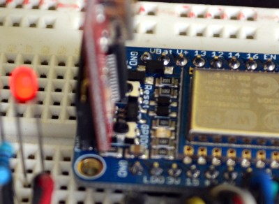 To the right I tried out my 5V Sparkfun FTDI board and as advertised, the HUZZAH can be programmed with either 3.3v or 5V logic levels.
The one thing I noticed is that the two buttons are a bit tricky to get at with the programmers connected, especially the FTDI board. For the second module I may supply my own right-angle header to get around that. Of course doing so would cover part of the breadboard so this is probably six of one, half dozen of the other.
I love it that they supply the pin headers but don’t solder them. Sometimes I prefer pin sockets or unpopulated pads, and this makes it easy for me to make that choice like the right-angle one I mentioned above. It’s something small but I also appreciate that the pinheaders in the package were not the minimum number necessary for this board — there were a few extra pins. You need to break them off and sometimes they can break one pin over from where you expected. If it were the minimum number you would either start over or solder a single pin at the end of the row (not ideal). If you screw up snapping these you could conceivably use a set of three pins and the rest as one unit to fix your mistake. Maybe I’m weird but it’s the small things in life!
Programming Options: NodeMCU and Lua
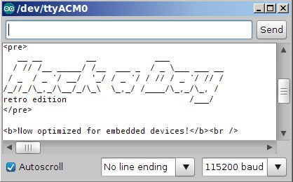
The board ships with this firmware on it. I was up and running with the Lua interpreter within three minutes of the package arriving at my door. Seriously, it took me longer to figure out if the USB-to-serial was green or white for TX/RX than it did to connect to my local WiFi Access point. Adafuit’s ‘Hello World’ walkthrough gets you going if you haven’t given this a try before.
Programming Options: Arduino IDE
 Adafruit has a Board Manager for Arduino IDE. Perhaps this is common knowledge but I don’t often work with this IDE and it’s the first time I’ve run into it. What can I say, it kicks ass!
I hate setting up tool chains for new chips. With this you add a web address and port number, restart the IDE, and use the board manager to add support for this board. Sweet!
That turns this into an Arduino compatible board which solves something that has long bothered me. I’ve seen a ton of really simple Arduino projects that use the ESP8266 externally. Last month’s porting of the Arduino framework for these chips, coupled with this ready-to-go hardware does away with that nonsense. Seriously, the vast majority of those projects need little to no computing power and will work like a dream when directly programmed onto this chip.
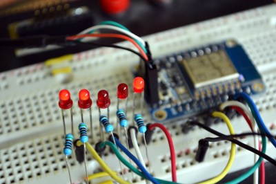 To prove my point, I knocked out this quick binary counter that uses five LEDs as outputs. I’m not leveraging any of the WiFi features on this, but the compiled binary is 174,358 bytes and the Arduino IDE reports this board has a max capacity of 524,288 bytes. It five I/O used for LEDs there are still four more digital pins, the two UART pins, and an ADC input.
Programming Options: esptool
Arduino will overwrite NodeMCU but that’s easy to reflash. I followed [cnlohr’s] direct programming guide to write the binary using esptool. Both this method and the Arduino method are directly programming the EEPROM on the module. This is exactly the same method you’d use if you wanted to develop natively using the Espressif or the Open Source SDKs. Here’s the commands I used to reflash the NodeMCU firmware:
sudo python esptool.py --port /dev/ttyUSB0 write_flash 0x0000 /home/mike/Downloads/nodemcu_latest.bin
Get the NodeMCU binary from their “latest” folder of github repo.
Conclusion
“Buy as many of these as [Phil] will make for us.” That’s what I’ve asked [Julian], the Hackaday Store manager to do. You should be able to get the Hackaday black version of this in a few weeks. Adafruit is currently sold out but I’m sure they’re racing to remedy this.
These are amazing little boards. The price of $9.95 is crazy considering what you get for it. I’m talking about the entire ecosystem which gives you multiple flavors of programming environments. Adafruit has done a lot to contribute to the code and knowledge base here, but a mammoth portion of this is community developed and I think coming in low on the price is one more way Adafruit has chosen to be a good guy in this ecosystem. The board has a ton of I/O for what it is, and if that’s not enough just, implement I2C, SPI, or UART to couple a beefy uC to the connectivity this one brings to the party. I see zero downside on this board. It’s as close to perfect as you can get.
Filed under:
Arduino Hacks,
Hackaday Columns,
reviews 


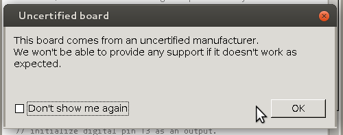 But before that, it’s time to bid farewell to the cheeky little popup window that would deliver a warning message when using a board bearing the USB IDs of their former-partner-turned-competitor. We absolutely