

DIY dtmf module and interfacing with arduino uno
In this post, we are going to make dtmf module and interface it using arduino.
 |
| My prototype |
Theory of DTMF:
Full form of dtmmf is dual tone multi frequency. The DTMF telephone keypad is laid out in a 4×4 matrix of push buttons in which each row represents the low frequency component and each column represents the high frequency component of the DTMF signal. Pressing a key sends a combination of the row and column frequencies. For example, the key 1 produces a superimposition of tones of 697 and 1209 hertz (Hz). Initial pushbutton designs employed levers, so that each button activated two contacts. The tones are decoded by the switching center to determine the keys pressed by the user.
| 1209 Hz | 1336 Hz | 1477 Hz | 1633 Hz | |
|---|---|---|---|---|
| 697 Hz | 1 | 2 | 3 | A |
| 770 Hz | 4 | 5 | 6 | B |
| 852 Hz | 7 | 8 | 9 | C |
| 941 Hz | * | 0 | # | D |
Circuit diagram of dtmf decoder ic:
 |
| Schematics |
where 104 is 0.1 uF ceramic capacitor.
If it is not working with you android, then download this android app.
Arduino code:
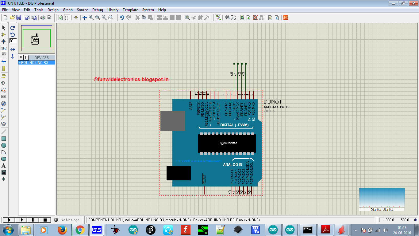 |
| Proteus design |
/* DOCUMENTATION:
* INTERFACING DTMF MODULE WITH ARDUINO
* IT HAS FOUR DIGITAL OUTPUT'S i.e. Q0, Q1, Q2 AND Q3
* Q3 IS CONNECTED TO DIGITAL PIN 2
* Q2 IS CONNECTED TO DIGITAL PIN 3
* Q1 IS CONNECTED TO DIGITAL PIN 4
* Q0 IS CONNECTED TO DIGITAL PIN 5
*
* We will check the output using serial monitor
* By- Chandan Kumar
* Contact: chandan90420@gmail.com
*/
int val=0;
boolean q0=LOW,q1=LOW,q2=LOW,q3=LOW;
void setup() {
pinMode(2, INPUT);
pinMode(3, INPUT);
pinMode(4, INPUT);
pinMode(5, INPUT);
Serial.begin(9600);
}
void loop() {
q0=digitalRead(5);
q1=digitalRead(4);
q2=digitalRead(3);
q3=digitalRead(2);
val=q0+(q1*2)+(q2*4)+(q3*8);
Serial.println(val);
delay(400);
}
Thanks for visiting my blog.
Stay tuned for more updates !!