Taming the Wobble: An Arduino Self-Balancing Bot
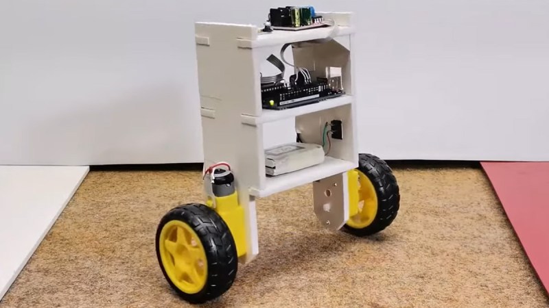
Getting a robot to stand on two wheels without tipping over involves a challenging dance with the laws of physics. Self-balancing robots are a great way to get into control systems, sensor fusion, and embedded programming. This build by [mircemk] shows how to make one with just a few common components, an Arduino, and a bit of patience fine-tuning the PID controller.
At the heart of the bot is the MPU6050 – a combo accelerometer/gyroscope sensor that keeps track of tilt and movement. An Arduino Uno takes this data, runs it through a PID loop, and commands an L298N motor driver to adjust the speed and direction of two DC motors. The power comes from two Li-ion batteries feeding everything with enough juice to keep it upright. The rest of the magic lies in the tuning.
PID (Proportional-Integral-Derivative) control is what makes the robot stay balanced. Kp (proportional gain) determines how aggressively the motors respond to tilting. Kd (derivative gain) dampens oscillations, and Ki (integral gain) helps correct slow drifts. Set them wrong, and your bot either wobbles like a confused penguin or falls flat on its face. A good trick is to start with only Kp, then slowly add Kd and Ki until it stabilizes. Then don’t forget to calibrate your MPU6050; each sensor has unique offsets that need to be compensated in the code.
Once dialed in, the result is a robot that looks like it defies gravity. Whether you’re hacking it for fun, turning it into a segway-like ride, or using it as a learning tool, a balancing bot is a great way to sharpen your control system skills. For more inspiration, check out this earlier attempt from 2022, or these self-balancing robots (one with a little work) from a year before that. You can read up on [mircemk]’s project details here.