In the Harry Potter series, a Muggle is a person who lacks any sort of magical ability. Growing up reading these books, one can only imagine what it would be like to cast spells using a wand. Well, wonder no more as a group of NYC Muggles decided to build their own smart wand that can ‘magically’ control devices over Wi-Fi.
The 3D-printed wand is equipped with a voice recognition module that lets users cast spells of their own with a flick of the wrist, like ordering takeout from delivery.com, turning the lights on and off, as well as playing and silencing music.
Other components include (what appears to be) a MKR1000 board, a LiPo battery, a PowerBoost, a microphone, a switch, and a vibrating motor that indicates when a command is recognized.
Those wishing to buy one are out of luck, as the creators reveal this was merely a fan-made project to celebrate the Harry Potter prequel “Fantastic Beasts and Where to Find Them.” You can read more about the Muggle Wand here!
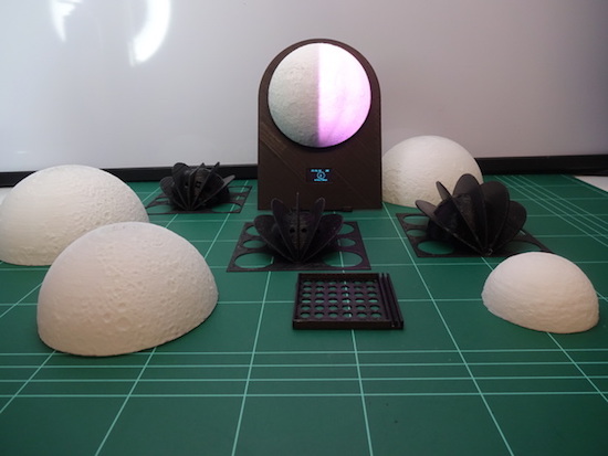
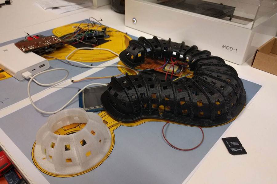
“Since there isn’t a supermoon everyday, make one for your bedside table!” This is exactly what G4lile0 set out to do using a 3D printer, an Arduino and some open-source tools.
The result was a moon phase clock consisting of a 3D-printed model and an LED strip to create the lunar phases. The lights are driven by an Arduino that precisely calculates which phase to show, as well as controls a 0.96″ OLED display revealing the date and time. Other electronics include an RTC module, a DTH11 sensor, a buzzer, and three push buttons.
The clock also features several modes, including an alarm, a wake-up light, a lamp, a thermometer, and a hygrometer. It can even help set the mood or start your next lunar rave with its relaxation and party-like special effects.
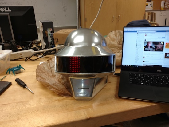
Though it’s been done before, this 3D-printed Thomas Bangalter helmet is absolutely amazing!
Daft Punk hasn’t toured in over a decade, but their music and general look seems to be becoming more and more popular. Perhaps this is due, in some small part, to the fact that Makers can now build a very good replica of their iconic helmets. Though the design for this helmet is available for download, looking at a design and building it are two different things.
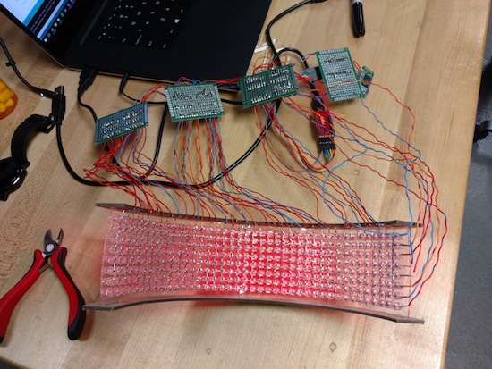
In addition to printing and finishing this prop (no small task), redditor “CrazyElectrum” did quite a bit of soldering. Getting all the electronic components to “play nice” with each other certainly took a good amount of work as well!
The helmet consists of 326 LEDS with 10 programmed displays, all controlled via Bluetooth and a custom smartphone app. Meanwhile, the ears are equipped with a pair of WS2812B strips. CrazyElectrum originally employed an Arduino Uno for its brains, but later moved to a Pro Mini due to its smaller form factor, and used six 74HC595 8-bit serial to parallel shift registers.
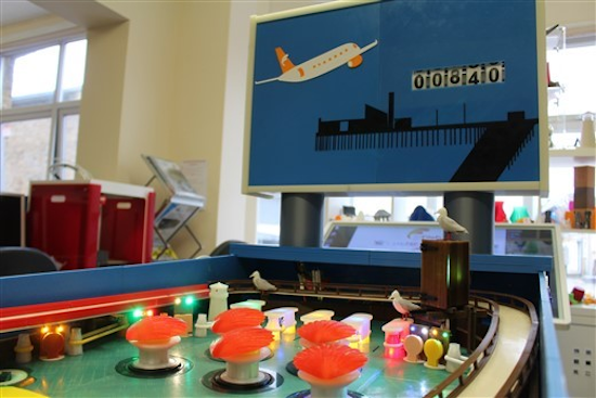
“Tony the Pinball Wizard” has successfully 3D-printed a fully-functional pinball machine.
The retired software engineer provides a detailed writeup, beginning with pinball’s roots in the 1700s to its eventual fall from popularity in the 1990s and 2000s. If you find this interesting, you could likely pick one up on Craigslist, but Tony instead decided to build his own.
This process isn’t for the feint of heart though, as it took him over 200 hours to design the game, and another 1,200 or more hours to 3D print everything. Materials included 8.5 kilometers of filament, of which 85 types were used. The whole thing is powered by a pair of Arduino Mega boards, needed to accommodate the massive number of inputs and outputs required.
The machine was brought to life and displayed inside 3D FilaPrint’s stand at recent industry trade show. You can see Tony’s excellent project in action below and read all about it here.
[Dr.Duino] recently completed the latest piece of what he calls “Interactive Furniture” – the GoonieBox. It took over 800 hours of design and assembly work and the result is fascinating. Part clock and part puzzle box, it’s loaded with symbols, moving parts, lights, riddles, sounds, switches, and locked compartments. It practically begs visitors to take a closer look.
The concept of Interactive Furniture led [Dr.Duino] to want to create a unique piece of decor that visitors could interact with. That alone wasn’t enough — he wanted something that wouldn’t require any explanation of how it worked; something that intrinsically invited attention, inspection, and exploration. This quest led to creating The GoonieBox, named for its twin inspirations of the 1985 film The Gooniesas well as puzzles from the game “The Room“.
Embedded below are two short videos: the first demonstrates the functions of the box, and the second covers the build process. There’s laser-cut wood, plenty of 3D printed parts, and a whole lot of careful planning and testing.
Puzzle boxes let people show off their creativity over a wide range of different executions, like these simpler laser-cut puzzle boxes and on the other end of the spectrum is this timed, multi-stage puzzle rigged to blow. Not only is this build one of the more complex ones we’ve seen, but I don’t think we’ve ever seen a puzzle box so carefully designed to also serve as a functional piece of decor. Great work!
With a shape reminiscent of a Game Gear, revised controls and hardware, Anthony Campusano’s rig looks extremely fun!
As reported on 3DPrint.com, Campusano’s Game Boy-inspired prototype was quite the crowd-pleaser at World Maker Faire in New York. Although wider than it is tall (like most portables to follow), and with many more buttons, this handheld console still screams “original Game Boy.” Perhaps this is because of its color scheme, or even the angle of the buttons.
Hardware consists of several platforms, including an Arduino to handle tasks such as status lights and battery level. The idea was inspired by Florian Renner’s similar concept, though he replaces the ideal of separate game cartridges with an SD card for storage.
I’m a trained architect, though I have industrial designer envy. In terms of electronics, I’m self-taught. When it comes to machine specs, the handheld is based on an Intel Core M. Controls are Teensy-based, and the status lights and battery level, etc. are run from an Arduino. Estimated battery life is about 3hrs +/- depending on the game.
Adjust the phase current, crank up the microstepping, and forget about it — that’s what most people want out of a stepper motor driver IC. Although they power most of our CNC machines and 3D printers, as monolithic solutions to “make it spin”, we don’t often pay much attention to them.
In this article, I’ll be looking at the Trinamic TMC2130 stepper motor driver, one that comes with more bells and whistles than you might ever need. On the one hand, this driver can be configured through its SPI interface to suit virtually any application that employs a stepper motor. On the other hand, you can also write directly to the coil current registers and expand the scope of applicability far beyond motors.
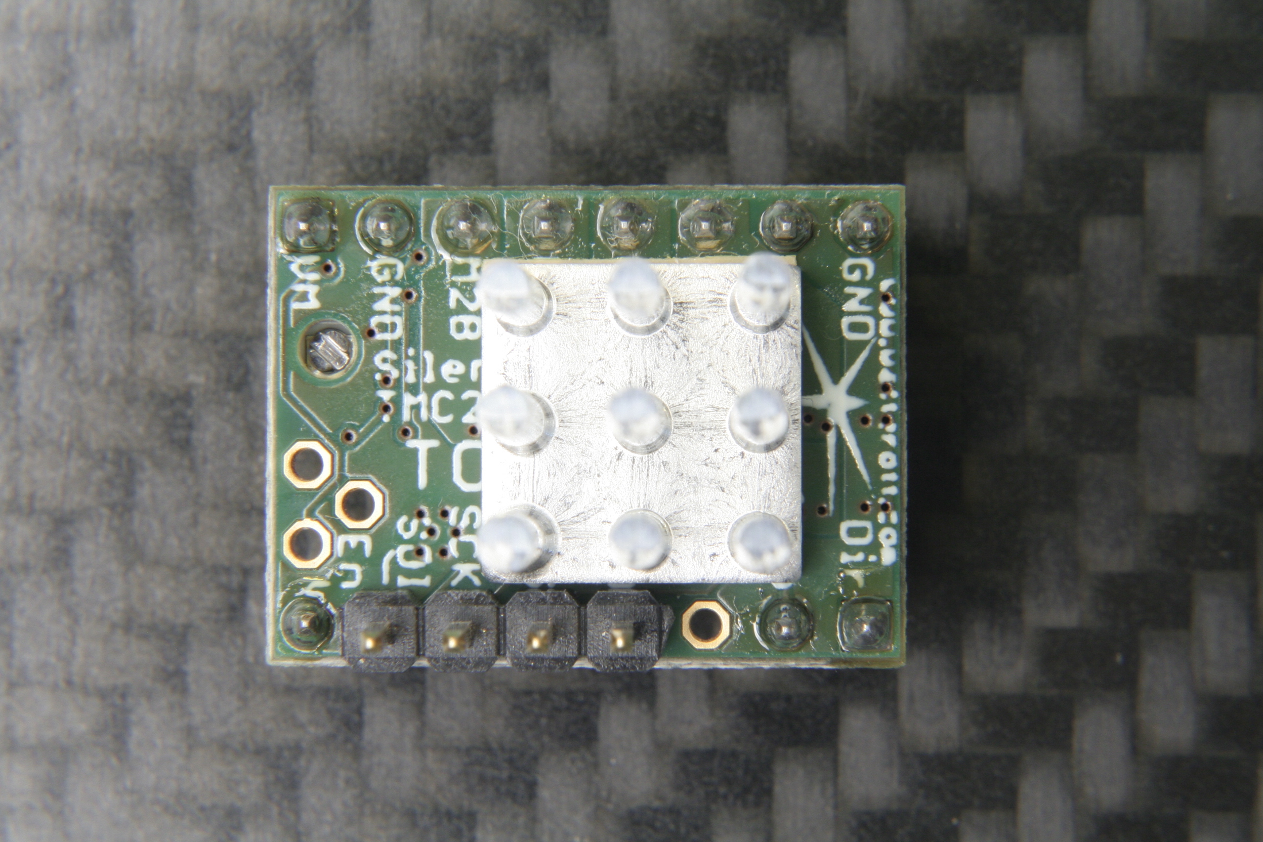
The TMC2130 SilentStepStick’s top side with SPI headers and heatsink.
Last month, we took a closer look at microstepping on common stepper driver ICs, but left out the ones that we actually want to use: the smart ones. Trinamic provides some of the smartest stepper motor drivers on the market, and since the German hacker store Watterott released their SilentStepStick breakout boards for the TMC2100 and TMC2130, they are also setting a new standard for DIY 3D printers, mills and pick-and-place robots. I recently acquired a set of both of them for my Prusa i3 3D printer, and the TMC2130 with its SPI configuration interface really caught my attention.
The TMC2130 SilentStepStick should not be confused with the — far more popular — TMC2100 variant. As the name suggests, it comes as a StepStick-compatible breakout board, and just like it’s famous sibling, features a Trinamic IC on the bottom side of the little PCB. Several vias and copper spills conduct heat away from the IC’s center pad, allowing a heatsink on the top side to effectively cool the driver.
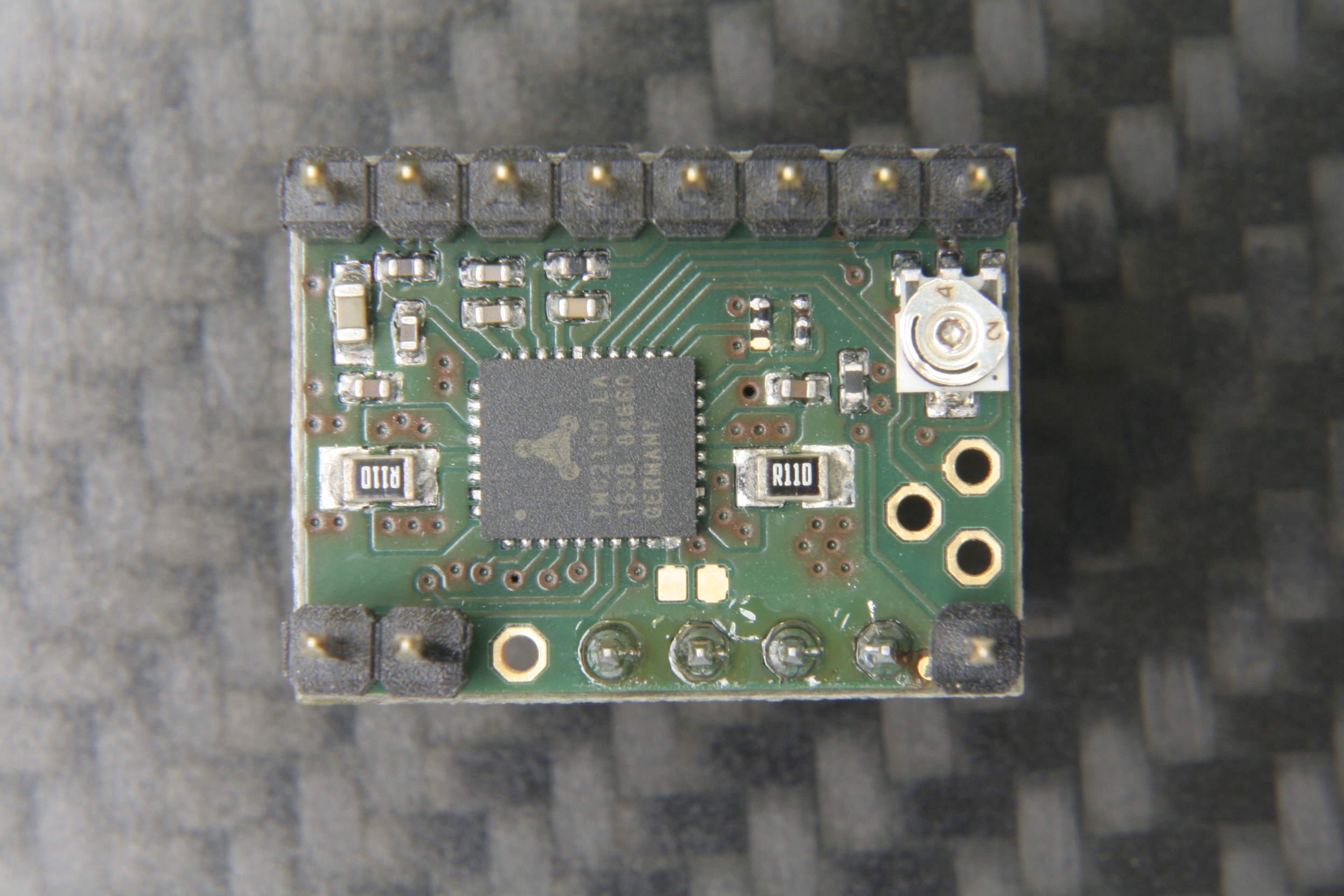
The bottom side with the stand-alone mode solder blob jumper next to the IC.
However, unlike the TMC2100, this one won’t let your motors spin right away. You’ve got two options: Hard-wire it in stand-alone mode, which practically turns it into a TMC2100, or hook up to its SPI-interface and dial in if you want your stepper motor shaken or stirred. In fact, plentiful configuration registers make the TMC2130 an extremely hackable chip, so I’m not even thinking about bridging that solder jumper on the SilentStepStick’s bottom side that activates the stand-alone mode.
First Steps
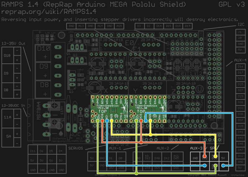
Wiring the TMC2130 to a classic RAMPS 1.4.
As said, before the driver does anything, it wants to be configured, and it’s worth mentioning that all configuration registers are naturally volatile, so if I want to use them in my 3D printer, I need to configure them as part of the printers startup routine.
The RAMPS 1.4 on my 3D printer breaks out the hardware SPI interface of the underlying Arduino through its AUX3 pin header, along with two additional digital pins (D53 and D49), which I used for the cable select signals. After crimping a cable to connect two TMC2130’s to the AUX3 header, I could start digging into the software part.
Watterott provides an example sketch, which writes a basic configuration to the driver’s registers and spins an attached stepper motor. Great stuff, but the datasheet describes 23 configuration registers waiting to be finely tuned, and 8 more to read diagnosis and status data from. So, I wrote a little Arduino library that would make the numerous configuration parameters available in a more practical way. From there, I could just include my library into the Marlin-RC7 3D printer firmware I’m using. Luckily, the current Marlin release candidate already features support for TMC26X drivers, so I could reuse some of its code to put together a Marlin fork that includes 59 of the TMC2130’s parameters in its define-based configuration files. And then, I could take the little buddies out for a spin.
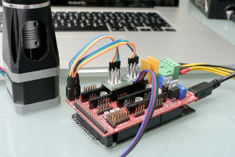
First steps on a RAMPS 1.4 on a somewhat-uino (sorry Massimo). The testing-contraption to the left is a NEMA 17 stepper motor attached to an encoder.
Taking Them For A Spin
With the hardware set up and the software working as supposed, I ran a few sanity tests: toggling parameters on and off and checking how the driver’s behavior changes during printing. Since the TMC2130 let’s you tune almost everything it’s doing, that’s a good first step that helps to eliminate some variables and picking others that are worth a deeper look. Most of the settings can be changed on the fly and mid-print, however, not all parameters can actually be safely changed while the motors are running.
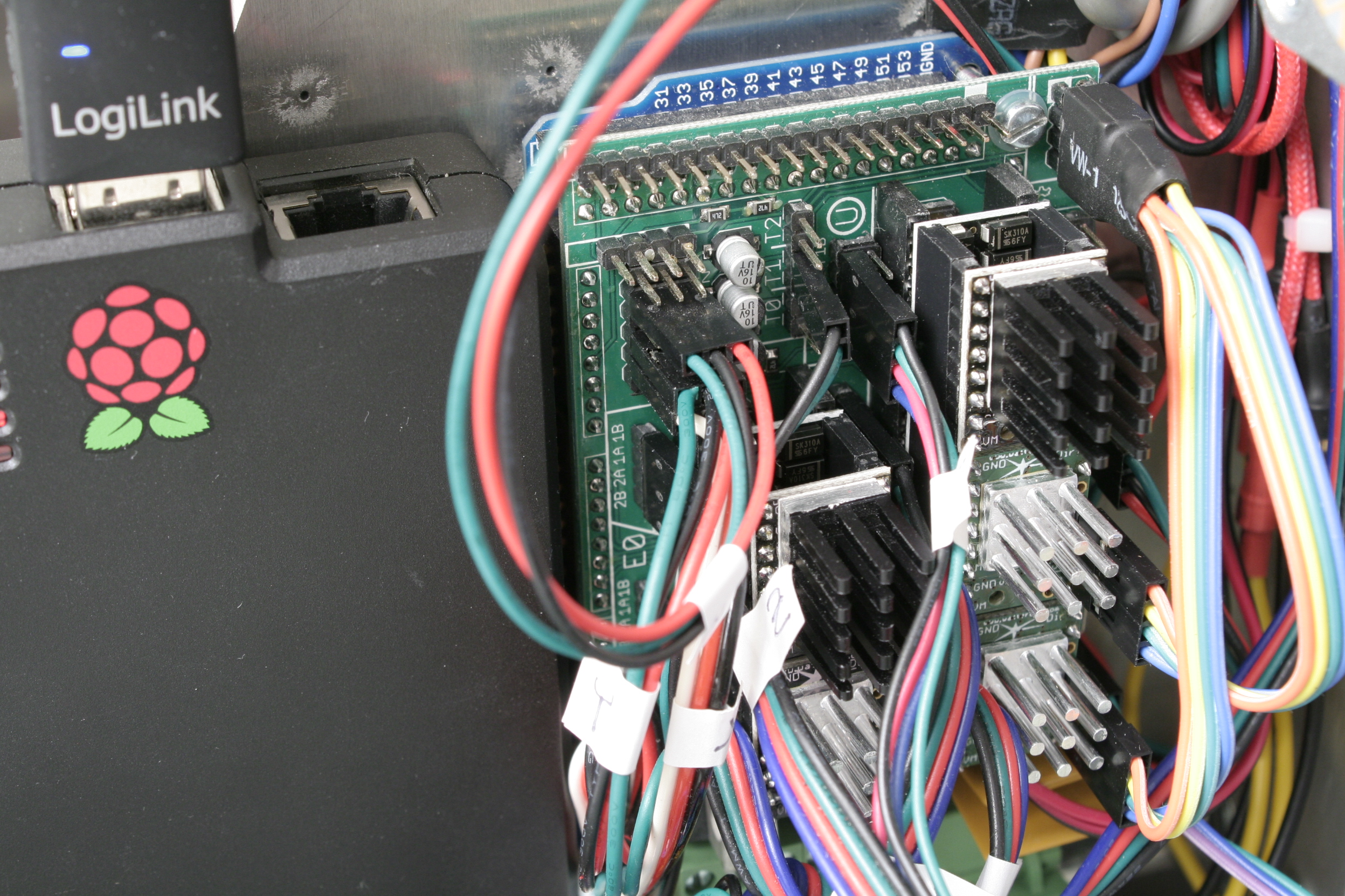
The TMC’s in service. I’m using the SPI-configurable TMC2130’s (silver heatsink) for the X- and Y- axis. The Z-axis and the extruder feature the TMC2100 (black heatsink). All of them are sitting on additional free-runner diode protection shields.An excerpt of Trinamic’s thorough quick start guide.
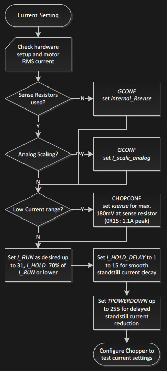
To actually tune the drivers for a certain application, Trinamic provides a quick start guide in the datasheet, as well as detailed information on each parameter, and on how they interact. Basically, the first step is adjusting the RMS coil current by using the onboard potentiometer on the SilentStepSticks. Then, we need to chose the analog input pin as a current scaling reference to actually make use of the potentiometer. The mentioned library lets me do this through a simple method:
myStepper.set_I_scale_analog(1); // 0: internal, 1: AIN
The running and holding current are the first real parameter that should be tuned, with the running current typically at the desired maximum current, and the holding current at 70% of this value. The delay between a stillstand and the transition from running current to holding current can be adjusted between 0 and 4 seconds, and for now, I set it to 4 seconds, practically disabling the current reduction while the 3D printer is running. The three values share one write-only register, so the corresponding method call looks like this:
and sets the running current to 100% (≙ 31), the holding current to about 70% of this value (≙ 22), and the delay between the two to 4 seconds (≙ 5).
I want torque, so I can leave stealthChop disabled. The datasheet suggests some starting values for configuring the chopper’s off time and the comparator’s blank time settings, but since it’s a key tradeoff between switching noise and torque, it makes sense to iterate through other values as well. The library methods for the two values look like this:
And finally, I need to pick a microstepping resolution and choose if I want to make use of the 256 microstep interpolation feature, covered later in this article:
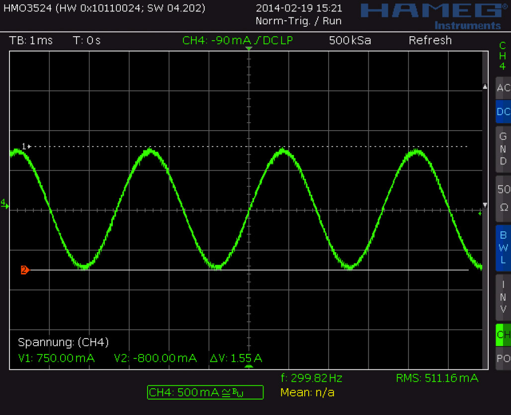
I have yet to walk through the entire tuning procedure, which includes monitoring the coil current on the scope and eliminating distortions in the zero crossing, but I’m getting a clue of the driver’s potential.
Juice
It’s maximum continuous RMS current of about 1.2 A per coil (at least in the QFN package on the SilentStepSticks) lets it look like a low-current driver, inferior to the common A4988 and DRV8825. In practice, it outperforms both of them by making intelligent use of a 2.5 A peak current margin. This gives it more than enough torque for 3D printing. I wouldn’t recommend pushing them over 0.9 A RMS though since the IC will momentarily pull more current if it needs more. For SilentStepStick users, that’s a Vref of 0.88 V. Through the SPI-interface, you can choose how much current you want to send through the motor coils when it’s spinning, and when it’s idling. You can choose after how many seconds it will start to decrease the current to a lower holding current when the motor is in standstill, and then to an even lower idling current. And, of course, you can also set it to squeeze out the maximum juice for everything.
Shifting The Gears
Where it starts getting interesting are settings like the high-velocity mode. Above a configurable velocity threshold, the driver offers you to automatically switch the chopper to a faster decay time to squeeze out some extra speed. You can also literally shift the gears by letting the driver internally switch from microstepping to full-step mode once it’s up to speed.
Microstepping
Choosing a finer microstepping resolution smoothens the stepper’s movement, reduces vibrations and sometimes even increases the positioning accuracy. However, it also multiplies the load on the microcontroller, which has to churn out 16, 32 or 256 times more step pulses per second. The TMC2130 lets you pick an input resolution between 1 and 256 microsteps per full-step, and then gives you the option of interpolating the output resolution to 256 microsteps. This allows for smooth operation even on increasingly retro 8-bit AVR motion controllers, which cannot deliver high step frequencies. Also, by configuring the TMC2130’s interface to double-edge step pulses, you can at least double the step frequency at almost no cost. Given that the modern IC still features the classic step/direction interface and even an enable pin, those few additional features actually make it a sweet drop-in upgrade for less-recent CNC and 3D printer electronics.
Noise Reduction
The TMC2130’s datasheet promises undistorted output with stealthChop.
Just like the TMC2100, the TMC2130 features two efficient and silent drive modes: spreadCycle, and stealthChop. The former delivers high torque at relatively low noise emissions, the latter one is almost inaudible but delivers a dramatically reduced torque. The flexible IC also allows you to tweak the chopper yourself to find the right balance between torque, noise, and efficiency for your application. One of the more noteworthy options in this regard is the possibility of randomizing the chopper’s off time. Since most of the audible noise is released due to dubstep the chopper busily switching the stepper motor’s coils, this option spreads the noise over a wider frequency range to subjectively silence the stepper motor.
Stall Detection
The TMC2130 notices when the motor is stalled and losing steps by measuring the motor’s back EMF. Along the way, it counts missed steps, allowing the controller to compensate for otherwise irreversible step-loss. It’s also a great way to react to obstacles rather than running into them full-force and, of course, the feature can be used as an axis endstop. Trinamic calls this feature StallGuard, and just like anything else in this motor driver, it’s highly configurable.
Direct Mode
Instead of letting the motor driver handle everything for you, you can also choose the direct mode. This mode practically turns the driver into a two-channel, bipolar constant-current source with SPI interface. You can still use it as a motor driver, but the possibilities reach far beyond that. It’s worth mentioning that the datasheet might be a bit confusing here, and the corresponding XDIRECT register actually accepts two signed 9 bit integers (not 8 bit) for each coil and operates as expected within a numeric range of, naturally, ± 254 (not ± 255) to vary the current between ± Imax/RMS..
The Takeaway
About half a year after the release of Watterott’s breakout board, the potential of smarter stepper motor drivers piqued the curiosity of the 3D printing community, but not much has happened in terms of implementation. Admittedly, it takes some effort to get them running. If you’re still busy dialing in the temperature on your 3D printer, you surely don’t want to add a few dozen new variables, but if you’re keen on getting the best out of it, the TMC2130 has a lot to offer: low-noise printing, high-speed printing, print interrupt on failure and recovery from lost steps. Because the driver IC is so hackable, it’s clearly intended to be tuned in to accommodate specific applications. Throwing it on a general purpose test bench probably won’t yield meaningful, general purpose results.
I hope you enjoyed taking a look at a smarter-than-usual stepper motor driver, as one of the new frontiers of DIY 3D printing, and as an interesting component with many other applications. If you’re thinking about experimenting with this IC or breakout board in your 3D printer, feel free to try my Marlin fork to get started. If you’re building something entirely different, the underlying Arduino library will help you out. Who else is using this part? I’ll be glad to hear about your ideas, applications, and experiences in the comments!
Suicide prevention charity R U OK? has partnered with digital innovation agency Fusion to create a fully-connected device in the form of a question mark with hopes of sparking a million conversations throughout Australia. Similar to the Olympic Torch, Quentin will be passed from person to person as it makes its way from town to town starting on Thursday, September 8th.
But unlike the Olympic Torch, the route is not planned. Instead, the journey is determined by the challenge it issues to each new keeper motivating them to reconnect face-to-face with people in their lives.
Quentin consists of a translucent 3D-printed shell, and is equipped with an Arduino/Genuino, some sensors, GPS, a display, and an array of LEDs that illuminate, animate and communicate. Users can interact with the device either by SMS or shaking it to receive their R U OK? challenge. Quentin also publishes its activity to the charity’s website, including distance travelled, challenges issued, and the number of keepers.
A team from the University of California, Riverside has developed a LEGO-like system of blocks that enables users to make custom chemical and biological research instruments quickly, easily and affordably. The 3D-printed blocks can create various scientific tools, which can be used in university labs, schools, hospitals, or anywhere else.
The blocks–which are called Multifluidic Evolutionary Components (MECs)–are described in the journal PLOS ONE. Each unit performs a basic task found in a lab instrument, such as pumping fluids, making measurements, or interfacing with a user. Since the blocks are designed to work together, users can build apparatus—like bioreactors for making alternative fuels or acid-base titration tools for high school chemistry classes—rapidly and efficiently. The blocks are especially well-suited for resource-limited settings, where a library of blocks could be utilized to create an assortment of different research and diagnostic equipment.
The project is led by graduate student Douglas Hill along with assistant professor of bioengineering William Grover, and is funded by the National Science Foundation. You can read all about the 3D-printed system here, and check out the video below which reveals an Arduino Uno being put to work.
Redditor SexyCyborg–who you may recall from her Hikaru Skirt last year–is back with another Arduino-driven, open-source wearable project. Inspired by traditional Chinese armor, the aptly named Infinity Skirt features an array of LED-lit mirror tiles that together form a flexible, reconfigurable matrix. Safe to say, she’ll certainly turn some heads at this October’s Maker Faire Shenzhen.
Every tile measures 66mm on each edge, and has four magnetic electrical conductors that can link it to it’s neighboring tile. So long as each row and column gets power, there is endless variations that can be tried. With an Arduino and LED matrix controller, each individual tile can be controlled so complex patterns can play across the surface. This is just a first prototype though so all the lights get power continuously and there is no matrix control.


