Buy Wise Clock 4 kit
The Wise Clock 4 kit includes the following parts (shown in the photo below):
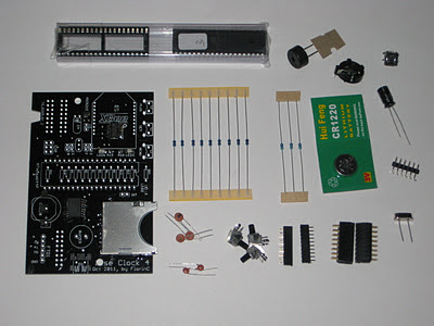


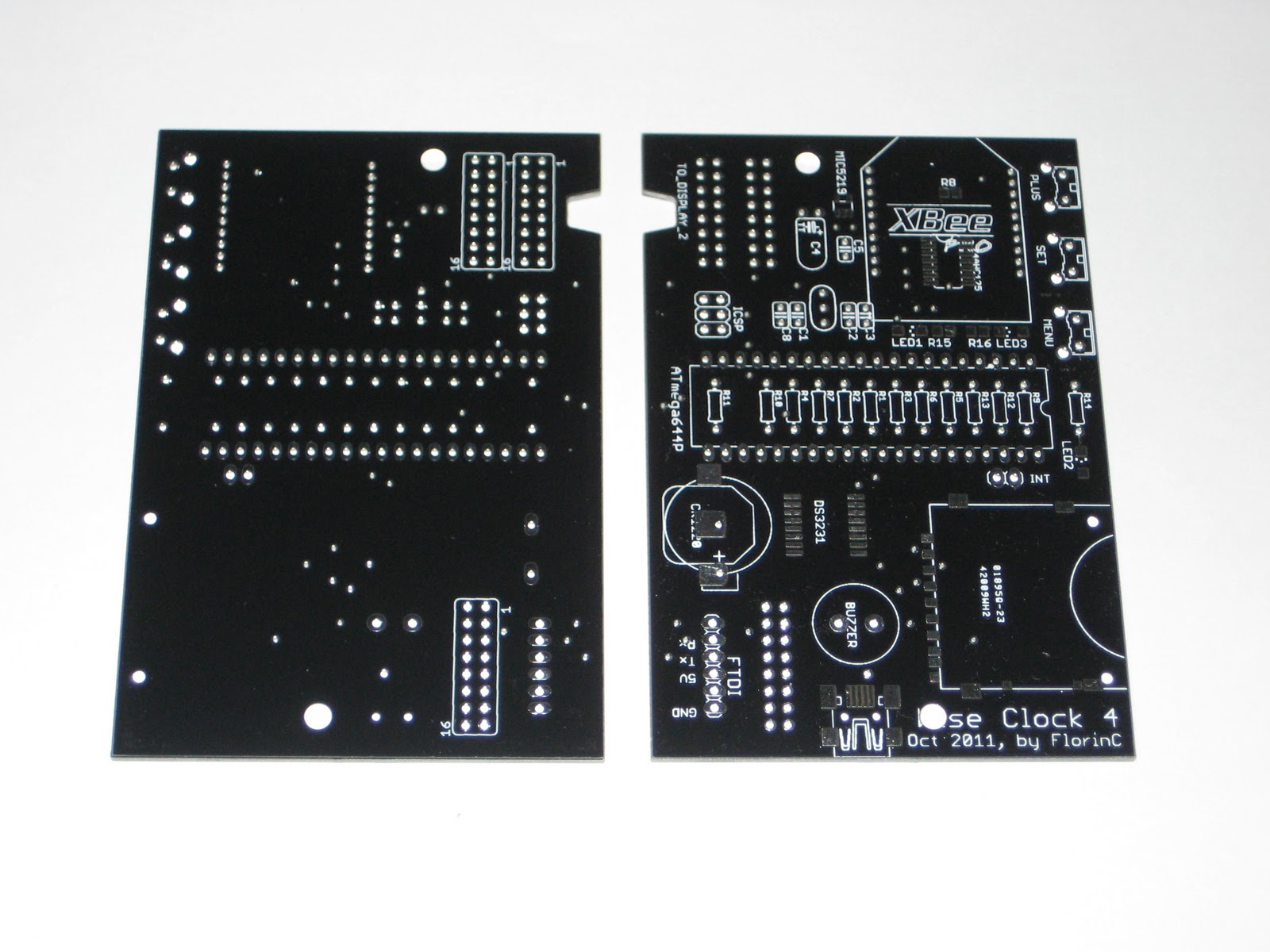
- PCB;
- SD card socket (pre-soldered);
- DS3231 extremely accurate RTC (real time clock) chip, soldered to the board;
- MIC5219 voltage regulator, soldered to the board;
- 74HC125 level shifter (5V to 3V3), soldered to the board;
- 2 SMD LEDs (soldered);
- 3 SMD resistors (soldered);
- ATmega644P, with the latest Wise Clock 4 software;
- 40-pin socket;
- 16MHz crystal;
- 2 x 22pF ceramic capacitors;
- CR1220 backup battery for RTC;
- holder for the coin battery;
- 3 x right-angle push buttons;
- 9 x 10k resistors;
- 3 x 4k7 resistors;
- piezo buzzer;
- USB miniB connector;
- 6-pin right-angle male header (FTDI connector);
- two 2x8-pin female headers (display connectors);
- two 10-pin 2mm female headers (XBee connectors);
- 220/470 uF electrolytic capacitor;
- 3 x 100nF decoupling capacitors.
Note that the first bunch of components in the list are SMDs and come soldered to the board (that is, I solder them for you).