

MixiClock - 4 digits displayed on 8x8 LED matrix
So far, on a 8x8 LED matrix, I have only seen the time displayed with scrolling numbers (beside the geeky binary/hex/tix/dice/dots/bars or other coded formats). There is simply not enough room to statically display 4 digits at once, since the tiniest set of human-readable digits can be defined in a grid not smaller than 3x5 pixels.
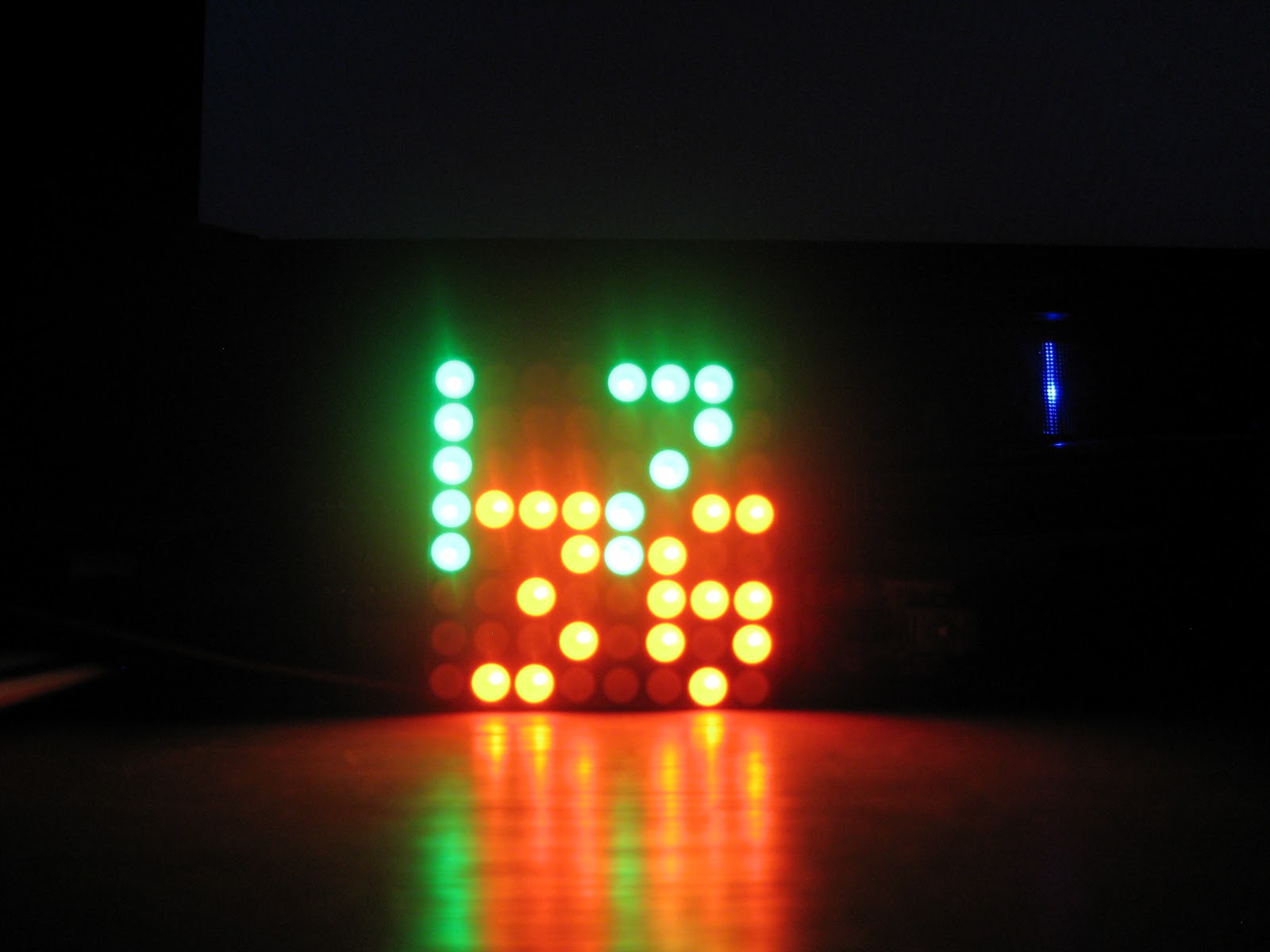
I challenged myself to find an intuitive way to display 4 digits on the "standard" 8x8 matrix. I figured that this is possible if using 2 colors. Even though they may overlap a bit (quite literally), digits of different colors can be easily distinguished. This is because the overlap makes a third color: in the case of the bi-color (red/green) LED matrix, it will be orange.
I focused on two aspects:
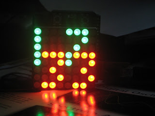

As you may have guessed, the top digits (green) indicate the hours, the bottom ones (red) the minutes. The position of the digits changes slightly depending on the combinations, so that there is no overlap or it is minimal (max 2 pixels, and those will be orange). The code is not final and I am sure it can be improved.
As always, comments and suggestions are welcome.

I challenged myself to find an intuitive way to display 4 digits on the "standard" 8x8 matrix. I figured that this is possible if using 2 colors. Even though they may overlap a bit (quite literally), digits of different colors can be easily distinguished. This is because the overlap makes a third color: in the case of the bi-color (red/green) LED matrix, it will be orange.
I focused on two aspects:
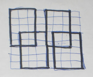
- font definition (3x5) as simple as possible, with minimal number of "on" pixels, but still readable;
// tiny 3x5 digits;
byte digit[10][5] = {
{2, 5, 5, 5, 2}, // 0
{1, 1, 1, 1, 1}, // 1
{6, 1, 2, 4, 7}, // 2
{7, 1, 2, 1, 6}, // 3
{4, 5, 7, 1, 1}, // 4
{7, 4, 7, 1, 6}, // 5
{3, 4, 7, 5, 2}, // 6
{7, 1, 2, 4, 4}, // 7
{7, 5, 2, 5, 7}, // 8
{2, 5, 7, 1, 6}, // 9
};
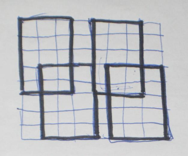
- optimal placement of the digits on the 8x8 matrix, so the overlap is minimal (sometimes 1 pixel, very rarely 2 pixels). The photo below shows the starting point. There is more tweaking of the positions in the code, depending on the combination of digits.
As for the name, there are not too many choices, most of them are already taken, so I hastily settled for "MixiClock" (I am open to suggestions though :).
The sketch, written for my 8x8 bi-color LED matrix shield (also used in the original glass-domed Wise Clock) can be downloaded from here. It should be easy to adapt it to any other RG 8x8 LED matrix. The code also features setting up the clock using two buttons.

As you may have guessed, the top digits (green) indicate the hours, the bottom ones (red) the minutes. The position of the digits changes slightly depending on the combinations, so that there is no overlap or it is minimal (max 2 pixels, and those will be orange). The code is not final and I am sure it can be improved.
As always, comments and suggestions are welcome.


