Posts with «uncategorized» label

Kickstarter, Trademarks and Lies

Kickstarter has undoubtedly changed the world by helping makers turn into an  industry to be reckoned with.
As with every brilliant invention the first prototypes always have a few issues that get fixed over time by trial and error. Figuring out a way to respond to issues and criticism quickly and effectively is the essence of growth and Kickstarter definitiely had done a lot but there is still a number of issues that are hard to deal with.

I want to show you an example of something that is happening to us right now.

A few weeks ago somebody launched a kickstarter for a project called smARtDUINO (notice the choice of lowercase/uppercase letters) that is supposed to be a better Arduino and all the rest. There is one of them every week so nothing new there.

The first issue that struck me was that right in the project title they claim to be the “former ARDUINO’s manufacturer”

Since I’ve never heard of this person I’ve emailed immediately the factory asking if they knew him.
Nobody had ever heard of him, then a long search started that ended with the realisation that he hired two factory workers who used to work for one of the many suppliers that our manufacturing partner uses.

So according to them, if I hire two factory workers from Ford I can claim I used to manufacture Ford cars…

When we got an email from an important worldwide reseller asking us if our manufacturing partner was behind this kickstarter, we really got worried that the confusion was going to create serious damages to us and decided to act.

We asked our lawyer in Italy to get in touch with this person to have some statements rectified while I got in touch with Kickstarter to see if they could act as a mediator in the dispute.

Based on the current available information, it seems that the company that owns the domain (Aldi Technology) doesn’t exist and the person who launched the kickstarter, who claims to be living in Italy (Mr. Dimitri Albino), actually moved to china years ago.

Italian speakers will find some old forum messages linking this person to some dubious activity.

Every week there is a kicstarter where, in a a way or another, somebody claims to be us… Either they call their project “Arduino” straight away or they ride the Arduino name in more clever ways. We usually email them but not all respond etc etc.

I wrote to kickstarter throught their public feedback form and emailed directly to somebody in marketing I had contact with in the past.

My point was that Kickstarter have to provide some kind of assistance when there are trademark violations or when somebody makes false statements.
Like many important websites have a clear and direct way to raise issues of trademark violations, Kickstarter should also make it easy to raise issues with them.

I got no reply from the marketing person and the next day I get this :
“Hi Massimo,

Thanks for writing in and bringing this to our attention. This is a matter that must be taken up directly with the project creator. You can contact them by clicking “Contact me” on the project page.

Best,
Kickstarter”

Well I don’t think Kickstarter can remove themselves from the picture, they are not a charity, they make money out of what they do. They should protect their users by better vetting who wants to be funded and by making it easier to raise issues about individual kicstarters.

What does the community think?

m

Arduino Blog 26 Nov 10:35

wJsonduino

Is a web server page that show the Arduino’s analog and digital input pin status, the status of the pin is transmitted with json, the page detect connection problems with the Arduino device and alert the user.
All refresh code run in browser and is write in javascript and ajax.

You can find it on the [webpage] coded by [bigjohnson].

Arduino Blog 17 Nov 17:03

arduino-line-follower-organ

Invention of a new Open Source mechanical musical instrument

Following the « DYI » trend, here comes a musical automaton created by [EricDuino]. This Arduino based autonomous robot is named « Line Follower Organ », « Orgue Suiveur de Ligne » in its maiden language.

What’s new with this instrument is that it moves along its partition in order to play it.

It’s still at a very early stage and it cannot play a full symphony or house music yet. Hopefully the Open Source community will soon make it play Electro Hop.


Ardupower

It’s a power stip driven remotely through an Ethernet network using telnet protocol.
The password and tcp parameters are saved in eeprom.
The user can give names to the six power out, that are also stored in eeprom.

Visit the page of [bigjohnson] on his site.

Arduino Blog 16 Nov 17:06

Arduino powered Lucky Cat as physical webcounter

Rebuilt my lucky cat: whenever a page of my website is loaded, the cat will be waving its arm. There’s a light sensor so when its dark, the cats RGB-LED is changing the color instead of waving the arm. Changing the color of the LED is also possible with one of the buttons on the cats ears. The other one is the reset button. Used an arduino ethernet, a servo, two buttons, an RGB LED and two small yellow LEDs. The seven segment display is one that I harvested from an old stereo. It’s driven by the arduino and two shift registers. unfortunately I’ve soldered that one together for an older project, so that it doesn’t fit into the cat too. It shows the number of pageviews of the website.

via [instructables] visit the page of [Janwil]

APDuino Project – Custom Monitoring without Coding


[srejbi] shares a new, programming-free, API-based way to programming Arduino: the APDuino project (minimum hw requirements: Arduino Mega 2560 + W5100 EtherShield). The Apduino relates to a peculiar approach towards Arduino that I noticed in the last years: using Arduino and making things without coding. This is a good thing for people that can’t code, but has to be simpler than learning code itself.

The APDuino Project provides a turn-key software solution for building custom monitoring and automation systems with custom rulesets (featuring expression evaluator with access to sensor and control arrays), cron-like scheduler, remote access and management via HTTP, SD and online logging and more…

All *without* programming (if using supported hardware components) … allowing DIY’ers to build their own automation systems much quicker and easier.

– The image collage attached is showing parts of 1 realization I built (I have 4 completely different systems running, all using the same software ) — This one pictures an aquaponics monitoring system with 16 physical sensors (lots of 1-wire DS18B20′s chained, DHT-11, photoresistors, HY-SRF05 with mechanically inverted reading surface providing tank level monitoring, radio-controlled sockets allow pump and fan controls).

Other systems feature components such as vibration detector, pH probe, BMP085,DS1307 RTC.

via [apduino.org], [Apduino on github]

Arduino Blog 15 Nov 12:42

Arduino a Robotica 2012


Anche quest’anno Arduino partecipa a Robotica – mentre non partecipa Makersitaly! – e ha scelto il mezzo della stampante termica in controtendenza con i mille volantini, flyer, cataloghi, allegati, biglietti da visita e tutta la montagna di carta che avrete nelle tasche alla fine dei tre giorni – giovedì venerdì e sabato – della manifestazione.

Siamo ad Impatto Zero, quindi non esageriamo neppure con la carta!

Questo post serve ad informare i lettori italiani della nostra partecipazione alla kermesse, ma anche ad offrire una pagina di informazione sulle attività che organizzeremo durante i tre giorni della fiera. Progetti con Arduino, regali & vendita delle Arduino Uno e Due ed altre mille informazioni che possono essere veicolate con la parola, ma che qui trovano un loro spazio online.

Quali sono le principali domande a cui Davide, Federico e Davide (sì, saremo in due) potranno rispondervi? Ecco le mitiche FAQ!

Mi scusi, che cos’é Arduino?

Che cosa vuol dire Open Source Hardware?

Come posso entrare nel mondo di Arduino?

Cos’é l’Arduino Leonardo?

Cos’é l’Arduino Due?

Ho visto il wearable kit: dove lo trovo?

Arduino é una scheda elettronica con cui prototipare ambienti interattivi, giocattoli, interfacce… un sacco di cose insomma. E’ italiano. E’ opensource. E’ facile da usare. Questo é il video che ha fatto uno dei suoi inventori (sono più di uno in effetti) qualche hanno fa.

Open Source significa che rilasciamo schemi e programmi per poter riprodurre questa scheda. Magari potrebbe sembrare una follia, invece un molte persone nel mondo hanno cominciato a realizzare oggetti nello stesso mondo, basati su Arduino. Questa é un’altra presentazione dello stesso signore, che si chiama Massimo, in durante un suo intervento a TED Global (è in inglese, ma ci sono i sottotitoli sono in italiano).


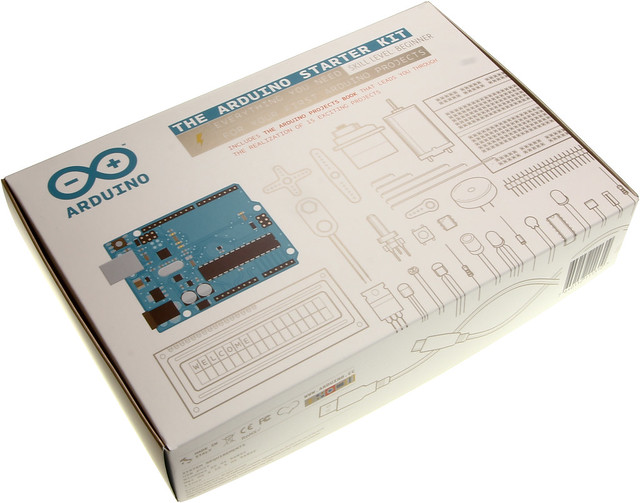
Qualche tempo fa abbiamo fatto un kit per iniziare con arduino, lo abbiamo chiamato Arduino Starter Kit!
In pratica é un libro che ti spiega come realizzare 15 progetti con Arduino. Le istruzioni sono in inglese, ma passo-passo. Massimo ha fatto dei video per spiegare come farlo e sono online qui.

L’Arduino Leonardo é presentata qui!

L’Arduino Due é presentata qui!

Trovate il post di lancio del wearable kit e molto altro qui

Per avere maggiori info su arduino potete scrivere sul forum in italiano, o cercare sullo store di arduino workshop o prodotti per iniziare a smanettare!

Ciao!

Arduino Blog 07 Nov 11:47

DIY less-expensive Thermal imaging camera

A thermal imaging camera is used for the purpose of energy auditing for homes and offices. Typically these require equipments such as FLIR B60 which are worth $5000 to $8000. This article by David Schneider however talks about a cheap DIY camera. Inspired by the award winning design using Arduino by two two 18-year-old students, Max Ritter and Mark Kohl, from Mindelheim, Germany.

The Schneider version of the thermocam, however, uses a slightly different partlist for the sake of robustness.

The parts used were:
Melexis’s MLX90614?DCI ($52), Arduino microcontroller($30), powder-coated metal enclosure for Arduino($30), Hitec HS425BB x 2 servos($13×2), DDT500H for pan-tilt mechanism($25), plastic mount for servos($5), COM-08654 Laser module with digital controller($19)

The applications were numerous:
- Checking around the home for weather-stripping faults. Even minor gaps were shown more clearly.
- Scanning people and imitating Kirilian photography to picture the actual energy that people emit.

For a more step-by-step on how to build, head here.

Happy building!

Via:[IEEE Spectrum],[Cheap-thermocam]

Arduino Blog 25 Oct 10:29

Sound Localization.

Well, it’s elementary simple in theory, how to do sound localization based on phase difference of signals, that received by two spatially distant microphones. The devil, as always, in details. I’ve not seen any such project created for arduino, and get curious if it’s possible at all. Long story short, here I’d like to present my project, which answer this question  - YES!

Moreover, quantity  of electronics components not much differs from what I’ve used in my previous blog.  Compare two drawings, you will notice only 4 resistors and 4 electret microphones were added! All circuitry is just a few capacitors, 9 resistors, one IC and mics.  Frankly speaking, writing a remix of oscilloscope, I was testing  an arduino analog inputs, keeping in mind to use it in junction with electret microphones in other projects, like sound pressure measurements (dBA),  voice recognition or something funny in “color music” series. As they call it – “a pilot” project?.  There are some issue (simplest ever) oscilloscope has when doing fast rate sampling on 4 channels (settings 7, 8 and 9 Time/Div ) I already described, so I slightly reduce sampling down to 40 kHz here.


Note: *Hardware would be different for arduino boards based on different chips, and must include pre-amplifiers with AtMega328 uCPU. 

One more important things to mention in this short introductory, as I used FFT algorithm for phase calculation ( I like FFT very much, you probably, already notice it ),

Arduino is capable not only track a MOSQUITO flying in your room, it could tell if it’s MALE of FEMALE !!!!!

                  SOFTWARE.

  As I say above, I choose 40 kHz for sampling rate, which is a good compromise between accuracy of the readings  and maximum audio frequency, that Localizator could hear. Getting signals from two mic’s simultaneously, upper limits for audio data is 10 kHz. No real-time, “conveyor belt” include 4 major separate stages:

  • sampling X dimension;
  • FFT
  • phase calculation
  • delay time extracting
  • sampling Y dimension;
  • FFT
  • phase calculation
  • delay time extracting

4 mic’s split in 2 groups for X and Y coordinate consequently. Picking up 4 mic’s simultaneously is possible, but would reduce audio range down to 5 kHz, so I decided to process two dimension (horizontal and vertical planes)  separately, in series. Removing vertical tracking from the code, if it’s not necessary, would increase speed and accuracy in leftover plane, of course. I’d refer you for description of the first and second stages to other blogs, FFT was brought w/o any modification at all. Essential and most important part of this project, stages 3 and 4.

Phase Calculation (3).

 Mathematical tutorial on a topic, I’m not any good as a teacher, so you better read somewhere else, to brush up a basic concept. Core of the process is arctangent function. This link says a number of cycles. In two words – too slow.  LUT ( Look Up Tables ) is the best solution for no-float uCPU to do complex math extremely fast, and reasonably (?) precise. Drawback of LUT is limited size, so it could be saved in FLASH memory, which in next tern  is also limited. This is what I did on “resource management” side: 1 kWords ( 16-bit integers, 2 kBytes) , 32 x 32 ( 5 x 5 bites) LUT, scaled up to 512 to get better “integer” resolution. There are a few values in top-right corner, that melted together as their differences are less than “1″ (not shown on the picture on right side). The “worst” resolution is in top-left corner, where “granularity” is reaching 256, or unacceptable 50% of the dynamic range. To stay as far away from this corner, I put a “Rainbow Noise Canceler” – single line with ” IF ” statement, which “disqualifies” any BIN with magnitude, calculated at the FFT stage, lower than 256.

IF(((sina * sina) + (cosina * cosina)) < 256) phase = -1;

 I called it “Rainbow” because of it’s shape, “red line” is an arc, going from 16 on top line to 16 on left side. Also, “Gain Reset” – 6 bit ( depends on the FFT size, has to be 6 bits for 128) reduced to 5 bits, in order to get better sensitivity. This two parameters / settings, 5-bit and 3.5 bit magnitude limit, create a “threshold” for weak spectral peaks. Basically, depends on application, both values can be adjusted in  different proportions.

 There are two category of tracking technics, with mic’s installed on moving platform, and stationary mic’s. First one is a little bit easier  to understand and build, requires Relative direction to sound source. This what I’ve done. Stationary mic’s approach, when motors are moving laser pointer (or filming camera) alone, would require Absolute direction to sound source, and must include stage #5 – angle calculation via known delay time. Math is pretty simple, acrsine function, and at this point only one calculation per several frames would be necessary, so floating point math wouldn’t be an issue at all. No LUT, scaling, rounding/truncation. Elementary school geometry knowledge – thats all you need.

Delay Time Extraction (4).

 Subtraction phase value of one “qualified” mic’s data pull from another, produce phase difference. To turn phase difference in delay time, division by BIN number is performed. Lets call this operation “Denominator” process.  The denomination is necessary, because all data after this step going to be combine and process together, doesn’t matter of wave length, which is different for every bin. Frequency and wavelength related to each other via simple formula:  Wavelength = Velocity / Frequency, where velocity is a speed of sound wave in the air ( 340 m/sec at room temperature). As distance between two mic’s is a constant,  sound with different wavelength ( frequency ) produce different phase offset, and denomination make them proportional. (WikiPedia, I’m sure, would explain this much better, mind you, I’m a Magician, not mathematician).

First picter on right side shows  ”Nuisance 3: Incorrect arctan” correction. You will find two lines with “IF” statements in the code relaited to stage #3.

Second one,  gives you idea why other correction at stage #4 is necessary As you can see, subtraction one arctan from another generates a rectangular “pulse” ( Diff. n. corr., violet line) whenever one function changes sign but other (delayed version) not yet. Light blue line (DIFF(B)) doesn’t have such abnormality. Math is simple, just two lines with “IF’s” in the same manner, only “double size” constants this time. 2048 on my scale corresponds to 2 x PI, 1024 – PI, and 512 – PI / 2.

Arduino has only 1 ADC, so there is always constant delay time equals to one sampling period ( T = 1/40 kHz = 25 usec), which also should be subtracted ( or added, depends how you associate input 1 and 2 – left / right side mic.)

Filtering.

 To fight reverberation and noise, I choose a Low Pass Filter, which I’d call here as a “Rolling Filter”. My research with regular LPF, shows that this class of filters is completely NOT appropriate for such type of data, due their high susceptibility to “spikes”, or sudden jump in magnitude level. For example, when system getting steady reading from 2-3 test frequencies with low values, let say -10, simple averaging ( should be -10 ) results will be corrupted with one accidental spike (magnitude +2000) during next 60 – 100 consecutive frames !!!  The Median Filter doing well eliminating sudden spikes, the same time is very hungry to CPU cycles, as it’s using “sort” algorithm each time new sample was arrived to the data pull. Having 64 frequencies, and setting filter kernel to 5 – 8 samples, arduino would be buried doing sorting at almost 40 ksps.  Even processing each frequencies data not individually,  and sorting only one 64 elements array still very time consuming job.  After thinking a while, I came up to conclusion, that “Rolling Filter” has almost the same efficiency as Median, but instead of “sorting” requires only 1 additive operation! On long run, the output value will “roll” and “stick” to the middle of the pull. ( Try to model it in LibreOffice. )  Adjusting “step” of the “Rolling Filter”, you can easy manipulate responsiveness,  which is almost impossible with Median Filters. (Things TO DO: Adaptive Filtering, real time adjustment depends on input data “quality”).

 To be continue…. Video will follows !

( Predicting your question, how “good” is localization?  Its about same, as Laser TRF (tracking range finder) has, look at other blogs for now to get impression.  In other words: ASTONISHINGLY GOOD,   a few (1 – 5) angular degree in closed environment.

Link to Arduino (Leonardo) sketch:  Localizator-beta-9.


Audio VU meter (AC microVoltmeter) with Extra wide Dynamic Range 69 dB.

O’K, after having some fun with stereo version of the VU meter I described in my previous blog-post, now it’s time to do a serious stuff. Studio grade VU meter !!! 24 steps, equally spaced every 3 dB, covering Extra wide Dynamic Range from -63  up to  +6 dB.  Single (mono) channel this time, no messing around, absolute precision at the stake. Plus, it keeps absolutely Top-Flat linear frequency response from 40 Hz up to 20 kHz(*).


I’m not going into details of RGB LEDs Display, which has no modification since “Tears of Rainbow” project, only plates installed in one line, form a single GIGANTIC bar-graph. There are some minor changes in mixing colors data tables, but they intuitively understandable.  The most important feature in this project is autoscaling. As you, probably know, Arduino has 10 bits ADC. Only it can’t process negative half-wave, and for this reason it has only 9 bits available for AC measurements.  According to DSP theory, maximum dynamic range is:

DR = 1.77 + 6.02 x B = 1.77 + 6.02 x 9 = 55.95 dB.

 As input audio waveform represents anything but perfect peak-to-peak 5V sine-wave, real dynamic range would be lower. How much? In first, there is a hardware limits.  OPA (NE5532), which is:

  • very low noise !!!
  •  high output-drive capability;
  •  high unity-gain and maximum-output-swing bandwidths;
  •  low distortion;
  •  high slew rate;
  •  input-protection diodes, and output short-circuit protection

 but, unfortunately,  isn’t rail-to-rail type. Test results show, that compression  become noticeable (~1 dB) when not scaled magnitude approaches level about 50 dB. That is in good agreement with observed on oscilloscope not distorted deviation peak-to-peak 2.5 V. Or only half of full range of 5V. And as theory says, half is one bit less, and real DR = 1.77 + 6.02 x 8 = 49.93  (~50 dB). In second, audio data is processed on “block” structure basis. It means, having average of the block 50 dB, doesn’t mean that there was no spikes in the sampling pull, that obviously would be clipped and introduce error in the measurements results.  This phenomenon is defined as Crest Factor. Different sources estimate crest factor of musical content between 10 – 20 dB.  So, taking direct approach, Arduino with OPA mentioned above as front-end could accurately cover only:              50 – 20 = 30 dB.  To get wider dynamic range, I have to scale input amplifier gain, and this is exactly what I did, building amplifier in two stages and selecting one cascade (by-passing second one) or two cascades using internal ADC multiplexer. As there is no switching IC in analog signal path involved, gain is defined with high stability, could be one time precisely measured – calibrated via coefficient stored in EEPROM (nice feature to add).

On the right side there are electrical drawings of “slightly” modified kit,  where stereo amplifier was converted into 2 stage mono version. First stage, with gain about  G1 = 1 + 10 k / 1 k = 11  is necessary to “bump-up” line-level signal, to create DC bias required for correct operation of the ADC, and also served as buffer to lower signal source impedance, as it seen by ADC input.  I set a gain of the second stage amplifier at 40 dB:  20 x Log_10 ( G2 ),     where    G2 = 1 + 100 k / 1 k = 101.

IMHO, setting gain limit for only 30 db per stage as it follows from paragraph above, is overkill, and would be justified for “real-time” radio broadcasting or audio processing for storage media, when high fidelity of audio program must be preserved. For visual display “clipping” of bursts in signal is not noticeable at all due high refresh rate of display, 78 Hz. Human just can’t see, if LED lights-up with such speed.  For steady AC amplitude measurements (micro Voltmeter mode) this is not a problem at all, and headroom as small as 3 dB would be sufficient, leaving wide 47 dB per stage.

 Software

  There are two thresholds are defined in program, where switching between one or two stage amplification is happening:

      if ( magn_new <=  44 ) sensitv = 1;

      if ( magn_new >= 47 ) sensitv = 0;

  44 and 47, with hysteresis 3 dB. First line defines switching to high sensitive mode (overall gain 1100), and second line, does exactly opposite. Look at the chart, hope it would save me a million words -);

 Couple words on using this device as precise AC micro-voltmeter. Having 1100 overall amplification as add-up to already quite sensitive Arduino ADC, driving overall sensitivity to enormously  5 / ( 1024 x 1100 ) = 4.439 uV Special care should be taken on grounding, shielding of amplifier PCB, probably, EMI suppressor ferrite chokes wouldn’t be an excess in power line and signal path.   In my project, w/o any modification to original kit’s board (except couple jumper wires to cascade two stage amplifier) of course, I was not expecting to get to such high sensitivity level. Moreover, in project arduino is driving LED display, “ADC noise reduction mode” is off, plus ADC is working on double speed – preselector set to 250 kHz!!!  And this is why constant 14 was subtracted in software from magn_new, just before it goes for BarGraph “mapping” procedure:

      magn_new  -= 14;

Basically 14 is a noise flour of my analog front-end.  Approximately 51 micro volts AC is turning on first LED bar. Look at the table, which reflect my current hardware set-up.

* Other things to keep in mind, there is a “gap” 78 Hz wide in frequency range at 10 kHz,  It introduces a small error, about  78 / 20.000 = 0.39% in white noise measurements result. For musical content, which has really low power density level at 10 kHz, magnitude of error would be much lower, probably, less than 0.05 %.

 Running FFT in code creates great opportunity to reject any interference in the audio band. For example, if there is a noticeable hum from electrical grid lines in the content, issue easily could be fixed NOT including bin[1] in final sum of magnitude calculation. Though to make it works more efficient, some adjustment in sampling period would be necessary, setting bin[1] frequency precisely at 50/60 Hz.

 One more advantage of having FFT based  filtering     (primary mission is HPF, look in stereo VU meter, how long kernel of the FIR filter has to be otherwise), is great opportunity to create “weighting” A, B, C or D curve for audio noise measurements. (:TO DO).

 Link to Download Arduino sketch:  Audio_VU_Meter_Mono_69dB