

More thoughts on EKG
Before doing the EKG lab, we should definitely discuss safety concerns, including things like the following chart (information from http://electronicstechnician.tpub.com/14086/css/14086_34.htm):
| Human reaction at 60Hz | Current in mA |
|---|---|
| Perception—slight tingling sensation | 1.1 |
| Can’t let go (120 lb. person)—arm and hand muscles close involuntarily | 10.0 |
| Can’t let go (175 lb. person) | 16.0 |
| Can’t breathe—paralysis of the chest muscles | 18.0 |
| Heart fibrillation—rapid irregular contractions of the heart muscles, which could be fatal | 65.0 |
The very small voltages we work with (5–10 V DC) means that we rarely need to be concerned about safety issues in the lab. Most of the resistance of the body comes from the skin, and varies enormously according to how sweaty the skin is. Cleaning dead skin cells off (as is done with most preps for EKG electrodes) reduces the resistance of the skin quite a bit. DC is somewhat safer than AC, because skin is less conducting than the rest of the body, and so acts as a capacitor in parallel with a resistor. Puncturing or scraping the skin reduces resistance considerably.
It would probably be useful to have students measure the resistance between two Ag/AgCl electrodes and compute the currents that would flow at different voltages. When I tried this on two chest electrodes (just after showering, so clean, damp skin) I measured around 50kΩ. Pressing the electrodes more firmly against the skin dropped the resistance to 25 kΩ, and it gradually crept back up.
I keep thinking that the 3-wire design for EKGs is overkill. The 3rd wire seems to be just provided to bias the body to be between the power rails of the instrumentation amplifier. It should be sufficient to bias one of the electrodes with a large resistor to the reference voltage directly, rather than through the body.
I tried this. First I hooked up the 3-wire system of the 2-stage EKG amplifier (though there was a mistake on that post, as the Rgain resistor was really 4.7kΩ, not 820Ω). This was to make sure that I was getting good contacts and a clean signal. I then disconnected the bias lead and tried to bias the opposite end of the wires. This did not work at all. Disconnecting the bias wire resulted in a large signal with a period of 16.7ms (60Hz, though with a complex waveform). Adding resistors between Vplus and Vref, Vminus and Vref, or both, just made this noise worse. I then tried taking my body out of the loop, connecting a 25 kΩ resistor between the clip leads. Without the biasing resistors I saw the same complex 60Hz signal. It seems to come from capacitive coupling to the leads, as moving my hand closer or further from the leads changes the magnitude of the signal, and grounding myself eliminates it. Putting 24kΩ resistors between Vplus and Vref and between Vminus and Vref reduced the noise, but did not eliminate it. Touching either Vplus or Vminus was enough to produce huge noise again.
I tried another experiment, where I attached the ground electrode not to Vref directly, but through a 0.56 μF capacitor. This worked fine, even though there was no DC bias connection for the instrumentation amp inputs! It stopped working if I then touched either the +5V or 0V power rail—the DC bias is important, but my body was working as a pretty good capacitor, holding the DC bias for quite a while. It is clear that the AC path to ground is crucial also.
I found that I could clean up the EKG signal by putting a 0.56 μF capacitor between Vplus and Vminus—enough that the P part of the EKG was visible.
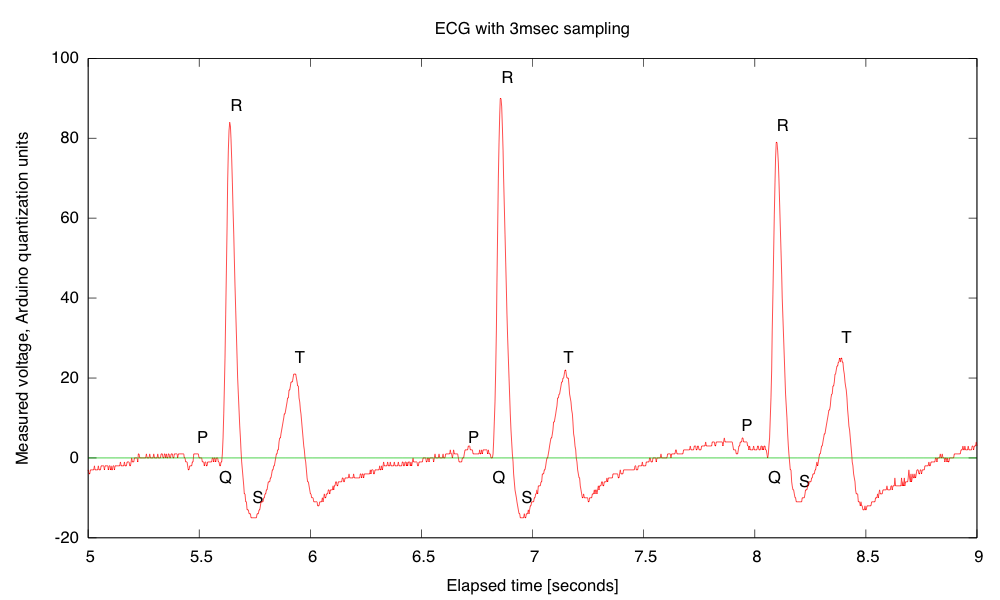
Clean EMG with P,Q,R,S,T parts of signal all clearly visible. The remaining noise seems to be mainly quantization noise in the Arduino analog-to-digital converter, which could be reduced by increasing the amplifier gain.
Since the remaining noise seemed to be all quantization noise, I upped the amplifier gain. Trying to raise the gain on the first stage did not work, so I raised the gain on the second stage.
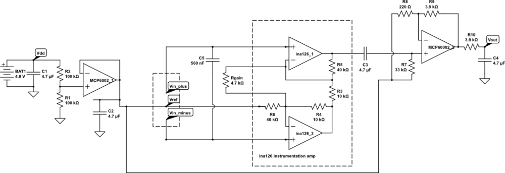
Higher gain EKG circuit, with capacitor on the inputs. The first-stage gain should be 22.02, and the second stage 18.73, for a total gain of 412.4.
The higher gain amplifier did produce good traces, with less evidence of quantization noise:
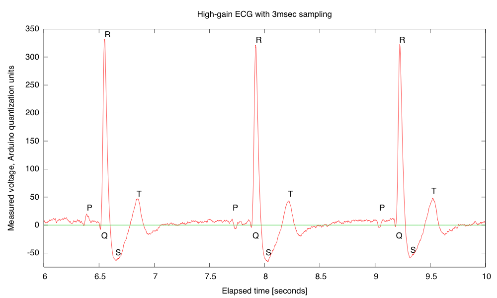
The “Arduino units” are 4.967 V/ 1024 = 4.851 mV at the output of the EKG, or 11.76µV at the electrodes. The R peaks are about 3.9mV and the S dips about -0.7mV. The first R-R interval is 1.368 seconds for a pulse rate of 43.86 bpm.
One thing that is important—the EKG readings are resting EKGs. If I flex the left pectoral muscle, I can swamp out the EKG signal.
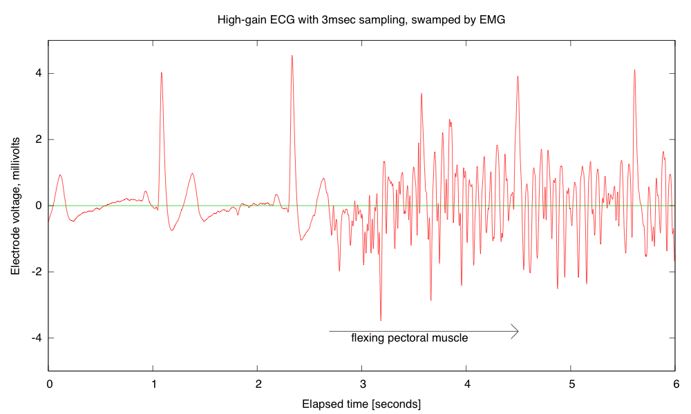
Every EKG is also an EMG (electromyograph), and flexing muscles between the electrodes (here the left pectoral muscle) can swamp out the EKG signal. I computed the electrode voltage from the recorded signal, the measured Arduino A-to-D reference voltage, and the gain of the EKG amplifier. The zero-reference is determined by recording the Vref signal as well as the EKG output signal. The quantization noise from the A-to-D converter is about 3μV (less than 1 pixel in this picture).
Filed under: Circuits course, Data acquisition Tagged: Arduino, bioengineering, circuits, course design, ECG, EKG, electrocardiogram, instrumentation amplifier, op amp, pulse

