Posts with «led hacks» label

Dinural Reef Control Realistically Insolates Your Aquarium

[Phillip]’s project is not just great for learning new words, it also shows just how complex natural systems can be. 

As we know from news around the word, reefs are delicate systems prone to damage from just about any imaginable threat. Escaped aquarium fish, sunscreen, and the wayward feet of well meaning tourists to name a few. So it’s no wonder that aquarium hobbyists sometimes go to incredible lengths to simulate the natural environments these creatures live in.

While [Phillip] is still tinkering with his designs for this project, we found the data he included really interesting. His goal is to be able to plug in any coordinate on the earth and have the lights replicate the location. That includes not just the sun, but also the light from the moon as many corals seem to only spawn during certain tides. Of course no LED is perfect so he’s even experimenting with putting light sensors under the water to provide a feedback loop to make it perfect.

We really like the ambition of this project and we hope he continues.

Hack a Day 04 Jan 06:00
arduino  coral  led  led hacks  light  reef  simulate  tide  

Optical Communication Using LEDs Alone

We’re all used to the humble LED as a ubiquitous source of light, but how many of us are aware that these components can also be used as photodiodes? It’s something [Giovanni Blu Mitolo] takes us through as he demonstrates a simple data link using just a pair of LEDs and a couple of Arduinos. It’s a showing off his PJON networking layer, and while you’d need a bit more than a couple of LEDs on breadboards for a real-world application, we still think it’s a neat demonstration.

PJON itself is very much worth a look, being an implementation of a robust and error-tolerant network for Arduinos and other small microcontroller platforms. It has a variety of communication strategies for various different media, and as this LED demonstration shows, its strength is that it’s capable of working through media that other networks would balk at. Whether it’s controlling home automation through metal heating ducts or providing an alternative to LoRa at 433 MHz, it’s definitely worth a second look. We’ve mentioned it before, but remain surprised that we haven’t seen it more often since. Take a look, the video is below the break.

Hack a Day 22 Dec 09:00

Big And Glowy Tetris Via Arduino

Tetris was a breakout hit when it was released for the Nintendo Game Boy in 1989, in much the same way that Breakout was a breakout hit in arcades in 1976. Despite this, gamers of today expect a little more than a tiny monochrome LCD with severe motion blur problems. Enter the LED Tetris build from [Electronoobs].

The build relies on a hacker favourite, the WS2812B LED string. The LEDs are set up in a 8×16 matrix to create the familiar Tetris playfield. Buttons and a joystick are then installed on the front panel to allow the player to control the action. An Arduino Mega runs the show, with a DFPlayer used to play the famous theme music as the cherry on top.

It’s a fun build that would be an awesome addition to any hacker’s coffee table. Big glowing LEDs make everything better, after all – this ping-pong ball display is a great example of the form. Video after the break.

Hack a Day 06 Sep 16:30

A Colorful Way To Play Chess On An ATmega328

We’ve all seen those chess computers that consist out of a physical playing field, and a built-in computer that would indicate where you should put its pieces while inputting the position of your pieces in some way. These systems are usually found in a dusty cardboard box in a back room’s closet, as playing like this is fairly cumbersome, and a lot depends on the built-in chess computer.

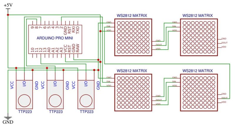
This take by [andrei.erdei] on this decades-old concept involves an ATmega328p-based Arduino Pro Mini board, a nice wooden frame, and 4 WS2812-based 65×65 mm RGB 8×8 LED matrices, as well as some TTP223 touch sensors that allow one to control the on-board cursor. This is the sole form of input: using the UP and RIGHT buttons to select the piece to move, confirm with OK, then move to the new position. The chess program will then calculate its next position and indicate it on the LED matrix.

Using physical chess pieces isn’t required either: each 4×4 grid uses a special pattern that indicates the piece that occupies it.  This makes it highly portable, but perhaps not as fun as using physical pieces. It also kills the sheer joy of building up that collection of enemy pieces when you’ve hit that winning streak. You can look at the embedded gameplay video after the break and judge for yourself.

At the core of the chess program is [H.G. Muller]’s micro-Max project. Originally ported to the Arduino Uno, this program outputs the game to the serial port. After tweaking it to use the LED matrix instead, [andrei.erdei] was then faced with the lack of memory on the board for the most common LED libraries. In the end, the FAB_LED library managed to perform the task with less memory, allowing it and the rest of the program to fit comfortably into the glorious 2 kB of SRAM that the ATmega328p provides.

Classic 8-bit chess engines are marvels of software engineering. Ever wonder how they stack up against modern chess software? Check out this article!

A Multi-Layered Spin On Persistence Of Vision

By taking advantage of persistence in human vision, we can use modest bits of hardware to create an illusion of a far larger display. We’ve featured many POV projects here, but they are almost always an exploration in two dimensions. [Jamal-Ra-Davis] extends that into the third dimension with his Volumetric POV Display.

Having already built a 6x6x6 LED cube, [Jamal] wanted to make it bigger, but was not a fan of the amount of work it would take to grow the size of a three-dimensional array. To sidestep the exponential increase in effort required, he switched to using persistence of vision by spinning the slight source and thereby multiplying its effect.

The current version has six arms stacked vertically, each of which presents eight individually addressable APA102 LEDs. When spinning, those 48 LEDs create a 3D display with an effective resolution of 60x8x6.

We saw an earlier iteration of this project a little over a year ago at Bay Area Maker Faire 2018. (A demo video from that evening can be found below.) It was set aside for a while but has now returned to active development as an entry to Hackaday Prize 2019. [Jamal-Ra-Davis] would like to evolve his prototype into something that can be sold as a kit, and all information has been made public so others can build upon this work.

We’ve seen two-dimensional spinning POV LED display in a toy top, and we’ve also seen some POV projects taking steps into the third dimension. We like where this trend is going.

The HackadayPrize2019 is Sponsored by:

A Ping Pong Ball LED Video Wall

Constrained builds are often the most fun. Throw an artificial limit into the mix, like time limiting your effort or restricting yourself to what’s on hand, and there’s no telling what will happen.

[bitluni] actually chose both of those constraints for this ping pong ball LED video display, and the results are pretty cool, even if the journey was a little rough. It seems like using sheet steel for the support of his 15 x 20 Neopixel display was a mistake, at least in hindsight. A CNC router would probably have made the job of drilling 300 holes quite a bit easier, but when all you have is a hand drill and a time limit, you soldier on. Six strings of Neopixels fill the holes, a largish power supply provides the 18 or so amps needed, and an Arduino knock-off controls the display. The ping pong ball diffusers are a nice touch, even if punching holes in them cost [bitluni] a soldering iron tip or two. The display is shown in action in the video below, mostly with scrolling text. If we may make a modest suggestion, a game of Pong on a ping pong ball display might be fun.

[bitluni] says that the display is on its way to Maker Faire Berlin this weekend, so stop by and say hi. Maybe he’ll have some of his other cool builds too, like his Sony Watchman Game Boy mashup, or the electric scooter of questionable legality.

Hack a Day 17 May 16:30

Freeform Wire Frame Tulip Blooms To The Touch

Holidays are always good for setting a deadline for finishing fun projects, and every Valentine’s Day we see projects delivering special one-of-a-kind gifts. Why buy a perishable bulk-grown biological commodity shipped with a large carbon footprint when we can build something special of our own? [Jiří Praus] certainly seemed to think so, his wife will receive a circuit sculpture tulip that blooms when she touches it.

via @jipraus

This project drew from [Jiří]’s experience with aesthetic LED projects. His Arduino-powered snowflake, with LEDs mounted on a custom PCB, is a product available on Tindie. For our recent circuit sculpture contest, his entry is a wire frame variant on his snowflake. This tulip has 7 Adafruit NeoPixel in the center and 30 white SMD LEDs in the petals, which look great. But with the addition of mechanical articulation, this project has raised the bar for all that follow.

We hope [Jiří] will add more details for this project to his Hackaday.io profile. In the meantime, look over his recent Tweets for more details on how this mechanical tulip works. We could see pictures and short videos of details like the wire-and-tube mechanism that allowed all the petals to be actuated by a single servo, and the components that are tidily packaged inside that wooden base.

Need more digital expressions of love? We have no shortage of hearts. Animated LED hearts, illuminated acrylic hearts, and talking hearts. We’re a little short on flower projects, but we do have X-ray of a rose among others to accompany [Jiří]’s tulip.

It’s done! Mechanical tulip as a present for my wife. When caressed it blooms into various colors. And will never fade. #freeform #jewelry #arduino pic.twitter.com/yDePeURXXd

— Jiří Praus (@jipraus) February 12, 2019

Gyro Controlled RGB Blinky Ball Will Light up Your Life

[James Bruton], from the XRobots YouTube channel is known for his multipart robot and cosplay builds. Occasionally, though, he creates a one-off build. Recently, he created a video showing how to build a LED ball that changes color depending on its movement.

The project is built around a series of 3D printed “arms” around a hollow core, each loaded with a strip of APA102 RGB LEDs. An Arduino Mega reads orientation data from an MPU6050 and changes the color of the LEDs based on that input. Two buttons attached to the Mega modify the way that the LEDs change color. The Mega, MPU6050, battery and power circuitry are mounted in the middle of the ball. The DotStar strips are stuck to the outside of the curved arms and the wiring goes from one end of the DotStar strip, up through the middle column of the ball to the top of the next arm. This means more complicated wiring but allows for easier programming of the LEDs.

Unlike [James’] other projects, this one is a quickie, but it works as a great introduction to programming DotStar LEDs with an Arduino, as well as using an accelerometer and gyro chip. The code and the CAD is up on Github if you want to create your own. [James] has had a few of his projects on the site before; check out his Open Dog project, but there’s also another blinky ball project as well.

Hack a Day 03 Nov 03:00

This Cup Holder Crystal Ball Tells Your MPG Future

Hybrid vehicles, which combine an eco-friendly electric motor with a gasoline engine for extended range, are becoming more and more common. They’re a transitional technology that delivers most of the advantages of pure electric vehicles, but without the “scary” elements of electric vehicle ownership which are still foreign to consumers such as installing a charger in their home. But one element which hybrids are still lacking is a good method for informing the driver whether they’re running on petroleum or lithium; a way to check at a glance how “green” their driving really is.

[Ben Kolin] and his daughter [Alyssa] have come up with a clever hack that allows retrofitting existing hybrid vehicles with an extremely easy to understand indicator of real-time vehicle efficiency. No confusing graphics or arcade-style bleeps and bloops, just a color-changing orb which lives in the cup holder. An evolved version which takes the form of a smaller “dome light” that sits on the top of the dashboard could be a compelling aftermarket accessory for the hybrid market.

The device, which they are calling the ecOrb, relies on an interesting quirk of hybrid vehicles. The OBD II interface, which is used for diagnostics on modern vehicles, apparently only shows the RPM for the gasoline engine in a hybrid. So if the car is in motion but the OBD port is reporting 0 RPM, the vehicle must be running under electric power.

With a Bluetooth OBD adapter plugged into the car, all [Ben] and [Alyssa] needed was an Arduino Nano clone with a HC-05 module to read the current propulsion mode in real-time. With some fairly simple conditional logic they’re able to control the color of an RGB LED based on what the vehicle is doing: green for driving on electric power, purple for gas power, and red for when the gas engine is at idle (the worst case scenario for a hybrid).

Check out our previous coverage of OBD hacking on the Cadillac ELR hybrid if you’re looking to learn more about what’s possible with this rapidly developing class of vehicle

Light Painting Animations Directly From Blender

Light painting: there’s something that never gets old about waving lights around in a long exposure photo. Whilst most light paintings are single shots, some artists painstakingly create frame-by-frame animations. This is pretty hard to do when moving a light around by hand: it’s mostly guesswork, as it’s difficult to see the results of your efforts until after the photo has been taken. But what if you could make the patterns really precise? What if you could model them in 3D?

[Josh Sheldon] has done just that, by creating a process which allows animations formed in Blender to be traced out in 3D as light paintings. An animation is created in Blender then each frame is automatically exported and traced out by an RGB LED on a 3D gantry. This project is the culmination of a lot of software, electronic and mechanical work, all coming together under tight tolerances, and [Josh]’s skill really shines.

The first step was to export the animations out of Blender. Thanks to its open source nature, Python Blender add-ons were written to create light paths and convert them into an efficient sequence that could be executed by the hardware. To accommodate smooth sliding camera movements during the animation, a motion controller add-on was also written.

The gantry which carried the main LED was hand-made. We’d have been tempted to buy a 3D printer and hack it for this purpose, but [Josh] did a fantastic job on the mechanical build, gaining a solidly constructed gantry with a large range. The driver electronics were also slickly executed, with custom rack-mount units created to integrate with the DragonFrame controller used for the animation.

The video ends on a call to action: due to moving out, [Josh] was unable to continue the project but has done much of the necessary legwork. We’d love to see this project continued, and it has been documented for anyone who wishes to do so. If you want to check out more of [Josh]’s work, we’ve previously written about that time he made an automatic hole puncher for music box spools.

Thanks for the tip, [Nick].