Posts with «ir thermometer» label

You can make this 3D-printed, Arduino-powered IR thermometer yourself

If you want to measure the temperature of an object, one very convenient way is to use an infrared thermometer. MN Maker didn’t have one, and after wondering just how hot a component was getting, he decided to simply build one.

His device utilizes an Arduino Nano for control, and resides inside a 3D-printed enclosure that he designed. Temperature sensing is handled by an MLX90614 IR thermometer on a GY-906 breakout board, and a small laser is used for aiming. Once the temperature is obtained, it’s displayed on an OLED screen in the back of the housing in both Celsius and Fahrenheit. 

Arduino code and print files are available via the project’s write-up.

DIY Thermal Imaging Done Low-Tech Style

[Niklas Roy] has always wanted to try out thermal imaging and saw his opportunity when he received one of those handheld IR thermometers as a gift. But not content with just pointing it at different spots and looking at the temperatures on the LCD display, he decided to use it as the basis for a scanning, thermal imaging system that would display a heat map of a chosen location on his laptop.

DIY thermal imaging system

He still wanted to to be able to use the IR thermometer as normal at a later date so cutting it open was not an option. Instead he firmly mounted a webcam to it pointing at the LCD display. He then wrote software on his laptop to process the resulting image and figure out what temperature was being displayed.

Once he got that working, he next put the thermometer on a platform with servos connected to an Arduino for slowly rotating it in the horizontal and vertical directions, also under control of the software on his laptop. Each time the thermometer measures the temperature of a spot, the software decodes the temperature on the LCD display and then tells the Arduino to use the servos to point the thermometer at the next spot to be measured. Each measurement takes a little time, so scanning an entire location as 70×44 spots takes around a half hour. But the end result is a heat map drawn on the laptop, done by a device that is low-tech. [Editor’s Snark: Because attaching a webcam and processing the images is “low-tech” these days.] He can overlay the heat map on a normal photo to see at a glance where the hot spots are.

The software he wrote is available on GitHub and the video below shows it in action. We’ve got to admit, it’s pretty awesome to watch. You can even see the heat map being filled in one measurement at a time.

[Niklas] is somewhat of a regular here on Hackaday and his projects span an impressive range of creative ideas. Check out his massive music construction machine, or his RC beer crate delivery robot, or his supersized DIY pinball machine. Whatever you do [Niklas], keep those creative juices flowing!


Filed under: misc hacks

Reading an IR Thermometer the Hard Way

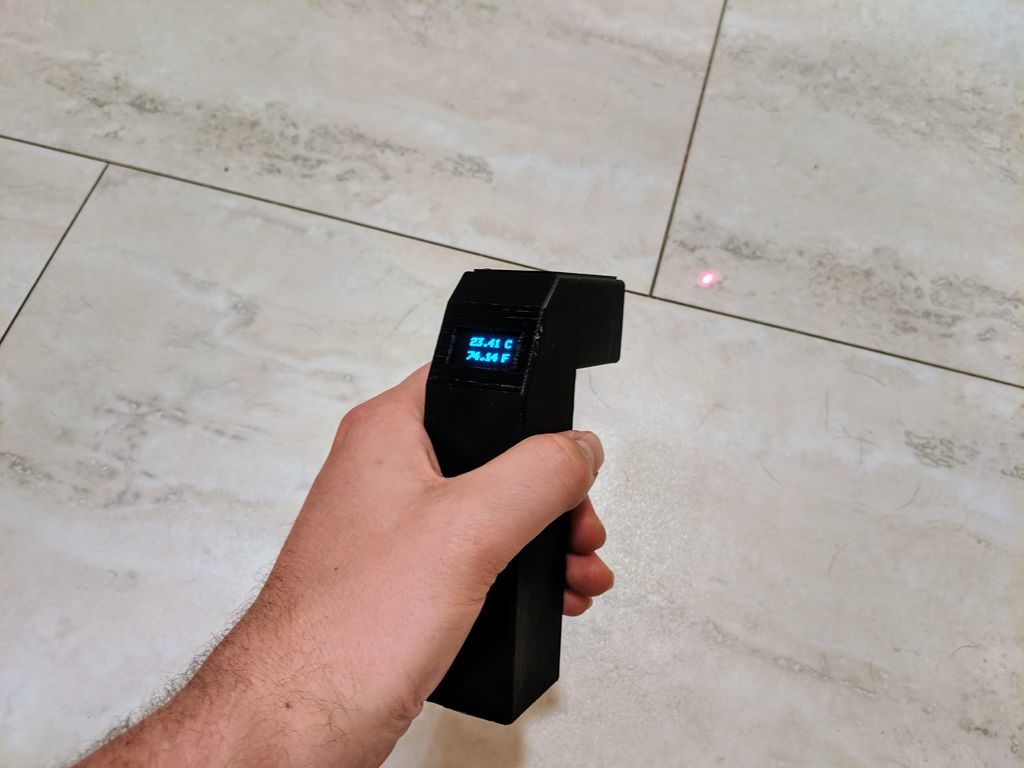
[Derryn Harvie] from the MakeHackVoid maker space hacked a $10 IR Thermometer and made it talk USB. Sounds easy? Read on.

He opened it up in the hope of finding, and tapping into, a serial bus. But he couldn’t find one, and the main controller was a COB blob – hidden under unmarked black epoxy. Normally this is a dead-end.  (We’ve seen some interesting approaches to decapping epoxy blobs, and even ICs with lasers.)

But [Derryn] went his own way – intercepting the data going from the micro-controller to the LCD display, and reverse engineering it using another microcontroller. He scraped off the solder mask over the tracks leading to the LCD display, and used an oscilloscope to identify the common drive lines. He then used a function generator to excite each of the LCD common lines and the segments lines to build a complete matrix identifying all the combinations that drove the segments. With all the information decoded, wires were soldered so he could hook up an Arduino, and the cut tracks repaired.

Since the LCD was a multiplexed display, the bias voltages were at four levels. Luckily, he could extract most of the LCD information by reading just eight of the segment drive lines, using up all of the analog inputs on the Arduino. Perhaps a different microcontroller with more ADC inputs would have allowed him to display more LCD functions. Well, he can always upgrade his upgrade later. If you have a similar hack to implement, then [Derryn]’s code could be useful to get started.

Thanks, [csirac2] for sending us this tip from MakeHackVoid.


Filed under: hardware