My Life in the Connector Zoo
“The great thing about standards is that there are so many to choose from.” Truer words were never spoken, and this goes double for the hobbyist world of hardware hacking. It seems that every module, every company, and every individual hacker has a favorite way of putting the same pins in a row.
We have an entire drawer full of adapters that just go from one pinout to another, or one programmer to many different target boards. We’ll be the first to admit that it’s often our own darn fault — we decided to swap the reset and ground lines because it was convenient for one design, and now we have two adapters. But imagine a world where there was only a handful of distinct pinouts — that drawer would be only half full and many projects would simply snap together. “You may say I’m a dreamer…”
This article is about connectors and standards. We’ll try not to whine and complain, although we will editorialize. We’re going to work through some of the design tradeoffs and requirements, and maybe you’ll even find that there’s already a standard pinout that’s “close enough” for your next project. And if you’ve got a frequently used pinout or use case that we’ve missed, we encourage you to share the connector pinouts in the comments, along with its pros and cons. Let’s see if we can’t make sense of this mess.
FTDI TTL Serial
The de-facto standard for a hacker’s TTL serial pinout is definitely the layout that FTDI uses for their USB/TTL serial cables. Said cable is just so handy to have on hand that you’d be silly to use any other pinout for the job. And the good news is that the rest of the world has basically joined in. From the Chinese “Pro Mini” cloneduinos to the Hackaday Edition Huzzah ESP8266 board, and from Adafruit’s FTDI Friend to Modern Device’s USB-BUB, almost everyone uses this pinout. A victory for the common man!

There is one slight point of contention, however, and that’s whether pin 6 is DTR or RTS#. We never use either, so we couldn’t care less, but if you’re counting on your programmer sending the DTR signal to enter programming mode on the device (we’re looking at you Arduino!) then you’ll want DTR on pin 6, and the original FTDI cable, ironically, has the “wrong” pinout. Perhaps that’s why Sparkfun avoided the whole debacle and went their own way, breaking out every signal off the FTDI chip into their own unique configuration.
If you’re only going to break out TTL serial lines, you’d be a fool to use any other pinout.
Modules and Other Communications
Unlike the case with simple serial, connecting various kinds of modules to mainboards is a difficult problem. Creating a single pinout or connector specification for many potential protocols or arbitrary signals is a Herculean task. Surprisingly, it’s been done a few times over. Here are some notables.
Pmod
Digilent makes a wide range of FPGA demo boards, and they needed an in-house standard pinout that they could use to plug into various add-on peripheral modules that they sell. Thus Pmod was born. It has since become a full-fledged, and trademarked, open standard that you can use in your designs. Here’s the PDF version of the specification for you to print out, so you know they mean business.
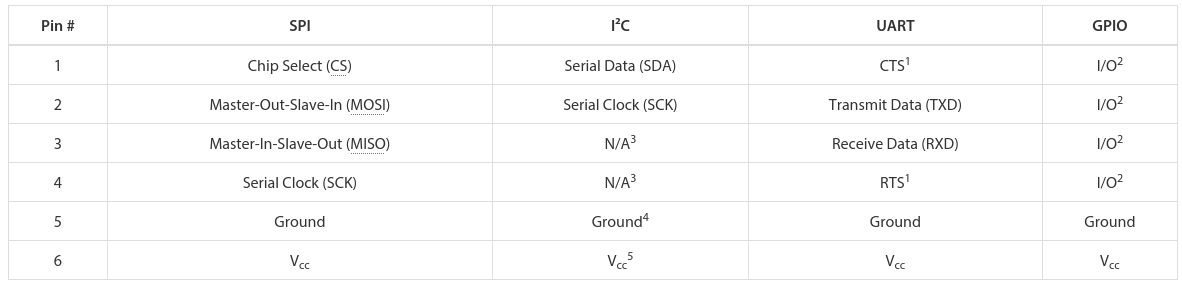
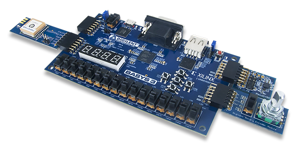 There are a few aspects of Pmod that we think are particularly clever. First, the number of pins involved is “just right” at six, and it’s easily expandable. They use standard 0.1″ pitch pins and headers. Two lines carry power and ground, leaving four free pins for SPI, UART, or whatever else. The specification is that all power and signal voltages are 3.3 V because they’re designed for FPGAs after all. You can mix and match if you know what you’re doing, but they won’t let you call it Pmod(tm).

If you need more than four signals, there’s a twelve-pin version which is just two six-pin Pmods stacked into a double-row header. The extra power and ground are redundant, but it makes a twelve-pin output very flexible, because nothing stops it from being used as two sixes. The standard also says that the twelve-pin headers are to be spaced at 0.9″ center-to-center, so you can even connect two of them together when you need sixteen board-to-board signal connections. We like the modularity and expandability.
Pmod connectors are multi-protocol, but for each protocol there is a single pinout. So there’s an SPI Pmod and an I2C Pmod, and the pins are always in the same place. There isn’t a Pmod standard for every conceivable application, of course, so there’s a GPIO pinout that gives you free rein over what goes where. We think that it would be nice if some additional notable protocols (I2S? one-wire? servos? analog stereo audio?) were included in the specs, but the community can also handle these lower-level details.
 In our eyes, Pmod is nearly perfect. It uses cheap hardware, is easily expandable, and the smallest incarnations are small enough to fit on all four sides of a one-inch-square board. If you’re willing to pay the brand-name premium, Digilent makes an incredible range of modules. We want to see more hackers outside of the FPGA scene get on it.
mikroBUS
 What Digilent is to development boards in the US, MikroElektronika is in Europe. While Pmod aims to be capable of doing anything, Mikro-E’s mikroBUS connector wants to do everything, which is to say it has I2C, SPI, UART, two voltages, and even a few extra signals all on the same pinout. Physically, it’s two single rows of eight pins, spaced 0.9″ apart side-to-side, which means it fits into a breadboard nicely. Here’s the spec in PDF.
The tradeoff here, relative to Pmod, is that a lot of pins go unused on any given design. With (only) one “analog” channel, you wouldn’t choose mikroBUS to send stereo audio, whereas nothing stops you from calling the Pmod’s GPIO lines analog and sending four channels of sound. But that mikroBUS gains is fool-proofness. (Well, they could have also made it asymmetric…) There’s no chance of a newbie plugging an SPI module in where an I2C module is expected and scratching their heads. With mikroBus, it should just work.
Microchip has added a mikroBus port to their Curiosity boards, and MikroElektronika makes a ton of modules. If your audience consists of beginners, and one footprint for all protocols, it’s worth considering.
Seeed’s Grove
 Meanwhile in China, Seeed Studios makes open-source modules, and makes them cheap. Their Grove connector uses only four pins, with power and ground among them. The have standard pinouts for UART, I2C, and for servo motors. Sensors and other analog peripherals are allocated one “primary” pin and one “secondary” and it’s assumed that you know what you’re doing. The idea behind their system is that you add a shield to your microcontroller board, and they break out the relevant pins into these four-pin Grove headers.
This is great for small things and I2C devices, which is Seeed’s catalog, but there just aren’t enough signal pins to run SPI or an analog RGB LED, for instance. But because of the small number of pins, they use very inexpensive polarized cables and shrouds that you can’t plug in the wrong way, and that take up relatively little board space. That’s Grove’s design trade-off.
Servo Motor control

Hobby servo motors need three wires: voltage, ground, and a signal to tell them where to point. There are three distinct ways to arrange these wires, but Futaba, HiTec, Tower, GWS, and JR servos all chose to put them in SVG (or GVS) order, and there’s no reason to buck the trend. (Airtronics, what were you thinking?!)
SVG is also a handy pinout to use for all sorts of one-signal sensors or actuators where space is a premium, and we’ve seen this in a few designs (here and here, for instance). But we’re torn. Relative to the Grove, for instance, you’re just saving one pin. Even the Pmod would work with only three pins’ overhead. Is that worth complicating your life with another pinout? If you need a lot of powered one-signal devices, or servos, it probably is, and you can hardly beat SVG or GVS, whichever way you look at it.
Arduino
Viewed in the light of any of the other module interconnection systems, the Arduino is the worst of all worlds. It’s monolithic like mikroBUS, but it’s gigantic — you have to build a 55×73 mm board and accommodate 30 pins and pass-throughs if you’d like it to be stackable. The pins have a funny spacing (that gap!), that doesn’t fit any normal protoboard. Nobody goes through the trouble of building a shield just for an I2C connection. No wonder most Arduino projects look like a breadboard hedgehog. About the only good thing we can say about it is that it’s hard to plug one in backwards.
There’s also the tiny little factor that there’s a million Arduino shields out there, a huge community built around them, and widespread support for them. Which turns out to trump all of the reasonable design concerns. (Shakes head.)
Miscellany
 Of course, there are other very specific pinouts that one might encounter, like the old ESP-01 module, or the XBee, or the nRF24. Adapting modules to fit boards is always going to be a pain, because the manufacturers will pick whatever suits them on that day. Programmer pinouts for specific microcontrollers are a similar story, as is JTAG, which is a beautiful standard with a dogs’ breakfast of pinout possibilities. (We could do a whole column!)
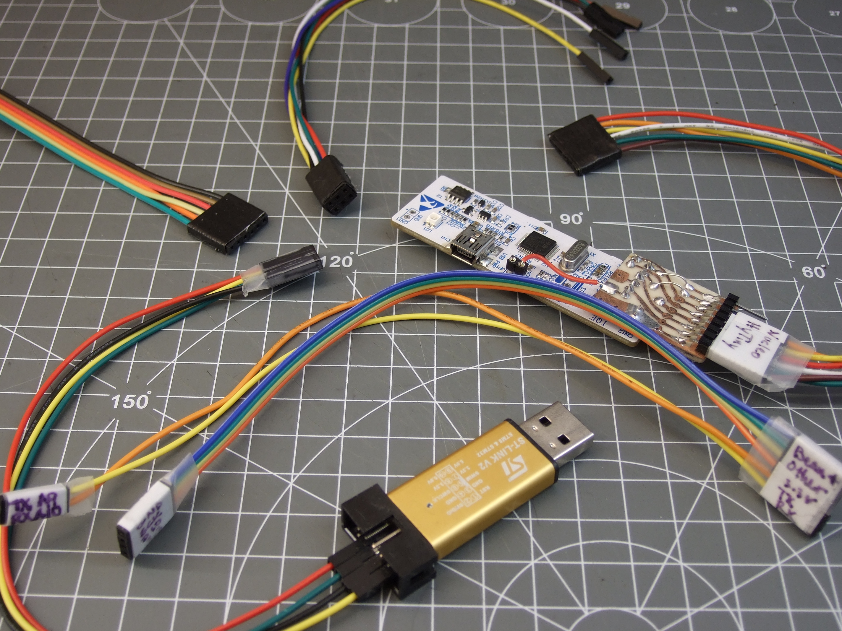
Faced with this inevitability, and the need for many one-off adapters, what can you do? What we do is buy a lot of those cheap “Dupont” female-to-female cables, get the connections working and tested, and then tape them permanently together and label them. It’s not as pretty as a dedicated PCB adapter, but it’s quick and easy and gets you moving on to what you wanted to do in the first place.
Wrapup and Recommendations
The goal of connectors, and their standards, is putting parts together. If you’re designing a sensor module with more than a couple components, and you want it to be maximally easy for yourself and others to hook up to whatever mainboard they’ve got, this is no easy task. The end result is a proliferation of translators, adapter boards, hats, shields, capes, or whatever else. We have a drawer and a half full, and we bet you do too.
What’s your solution to the ultimate connector conundrum? Are there important connector systems that we’ve left out? What are their design tradeoffs? How stoked would you be if things could just plug together? Let us know!
Thumbnail image courtesy of [Raspberry Pi Controller].
Filed under: Engineering, Hackaday Columns, hardware, rants