PART TWO
If you happened to land on this page and missed
PART ONE, I would advise you go back and read that section first. You may get lost coming in half way through the story. This is what you'll find in part one.
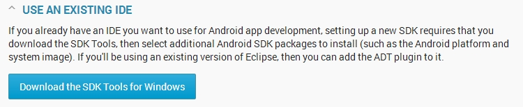
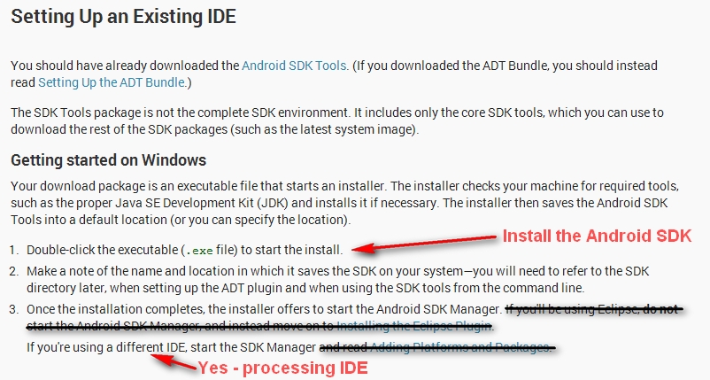
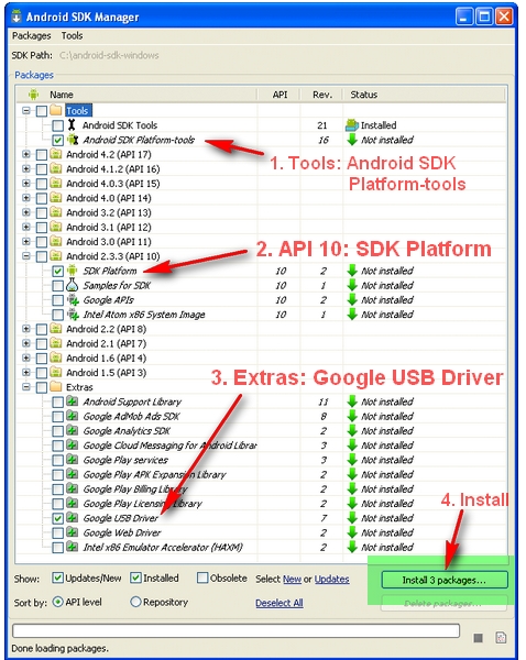
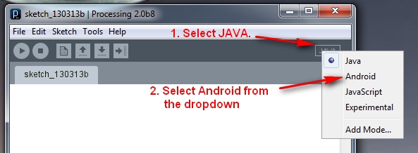
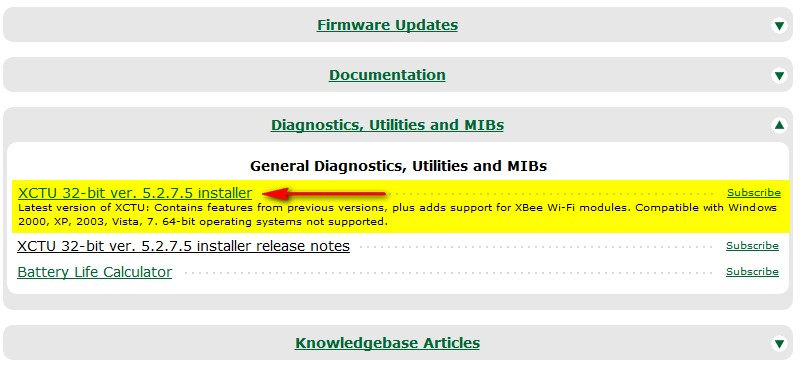
- Downloading and setting up the Android SDK
- Downloading the Processing IDE
- Setting up and preparing the Android device
- Running through a couple of Processing/Android sketches on an Andoid phone.
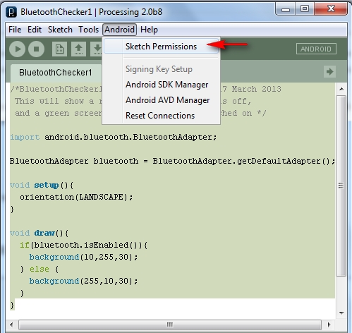
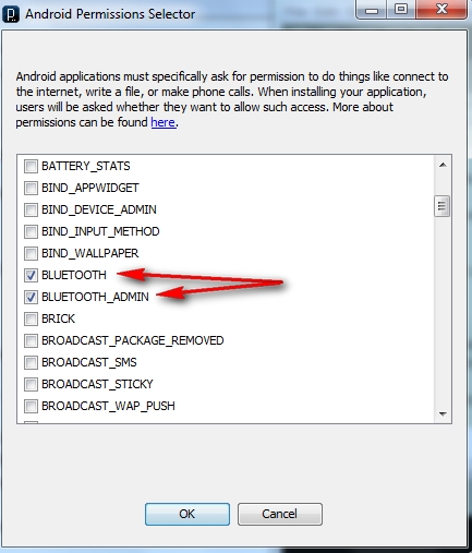
In the last sketch we checked to see if Bluetooth was enabled, if not, we then asked for permission to turn it on. The screen would then display a different colour depending on the Bluetooth state. So let's keep on going,
 ToastMaster - the master of all Toasts
I will now introduce you to Toast. What does "Toast" have to do with programming ? Toast is used by Android to quietly display little messages on the screen.
Have a look
here for a a quick introduction to Toast, otherwise have a look at the
Android Developers Toast information.
I will be creating my own method that relies on Toast to make the process of displaying messages easier. I have named this method: "ToastMaster".
A word of warning. Calling ToastMaster from within setup()
will cause errorsin the DiscoverBluetooth sketch (further down this page).
This will not happen in every sketch, but the Discoverbluetooth sketch has subActivities which may cause some sort of conflict.. I did warn you.
Here is a quick look at my ToastMaster method (no need to compile this code):
1
2
3
4
5
6
7
8 | /* My ToastMaster function to display a messageBox on the screen */
void ToastMaster(String textToDisplay){
Toast myMessage = Toast.makeText(getApplicationContext(),
textToDisplay,
Toast.LENGTH_LONG);
myMessage.setGravity(Gravity.CENTER, 0, 0);
myMessage.show();
} |
Here is a breakdown of what this is doing:
- Toast.makeText() - is used to construct the message to be displayed.
- getApplicationContext() - gets a handle on the Application
- textToDisplay - is obvious, this is the text you want to display.
- Toast.LENGTH_LONG - is how long you want the message to displayed for. (or LENGTH_SHORT)
- setGravity() - sets the message position on the screen, in this case I have chosen to center the text.
- show() - is used to actually show the message.
Broadcast Receivers : Looking out for Bluetooth devices
To listen/look out for any Bluetooth devices that are within range, we need to create and
register a Broadcast receiver.
When registering a BroadcastReceiver, you will need to tell the program what it is you are looking / listening out for. In our case we want to listen out for occasions whereby a Bluetooth device is FOUND. This is represented by:
If a BluetoothDevice is found, then the designated BroadcastReceiver will be called. We make our own BroadcastReceiver in order to perform a task such as displaying the name of the discovered device on the phone. However, before you will find anything, you have to start Discovering. This is done by calling the startDiscovery() method of the default Bluetooth adapter.
Here are the relevant components:
1
2
3
4
5
6
7
8
9
10
11
12
13
14
15
16
17
18
19
20
21
22
23
24
25 | BluetoothAdapter bluetooth = BluetoothAdapter.getDefaultAdapter();
BroadcastReceiver myDiscoverer = new myOwnBroadcastReceiver();
//Within Setup()
if (bluetooth.isEnabled()) {
registerReceiver(myDiscoverer, new IntentFilter(BluetoothDevice.ACTION_FOUND));
if (!bluetooth.isDiscovering()){
bluetooth.startDiscovery();
}
}
/* This BroadcastReceiver will display discovered Bluetooth devices */
public class myOwnBroadcastReceiver extends BroadcastReceiver {
@Override
public void onReceive(Context context, Intent intent) {
String discoveredDeviceName = intent.getStringExtra(BluetoothDevice.EXTRA_NAME);
//Display the name of the discovered device
ToastMaster("Discovered: " + discoveredDeviceName);
}
}
|
Discovering Bluetooth devices: putting it all togetherYou will notice that in the following sketch, we have to import a whole lot more. Which is why I have tried to break it down into bite size chunks, to help you digest it all. Now we will put it all together into a sketch which will
- ask to turn Bluetooth ON if it happens to be disabled.
- If you don't turn on Bluetooth, it will tell you that you need to turn it on.
- If you turn on bluetooth (or if it was already on), it will try to discover any bluetooth devices in range. These devices need to be made "discoverable" before running this sketch.
- If the phone finds a bluetooth device, it will display the name of the device and will change the background screen colour to GREEN.
Android/Processing Sketch 4: DiscoverBluetooth1
2
3
4
5
6
7
8
9
10
11
12
13
14
15
16
17
18
19
20
21
22
23
24
25
26
27
28
29
30
31
32
33
34
35
36
37
38
39
40
41
42
43
44
45
46
47
48
49
50
51
52
53
54
55
56
57
58
59
60
61
62
63
64
65
66
67
68
69
70
71
72
73
74
75
76
77
78
79
80
81
82
83
84
85
86
87
88
89
90
91
92
93
94
95
96
97 | /* DiscoverBluetooth: Written by ScottC on 18 March 2013 using
Processing version 2.0b8
Tested on a Samsung Galaxy SII, with Android version 2.3.4
Android ADK - API 10 SDK platform */
import android.content.BroadcastReceiver;
import android.content.Context;
import android.content.Intent;
import android.content.IntentFilter;
import android.widget.Toast;
import android.view.Gravity;
import android.bluetooth.BluetoothAdapter;
import android.bluetooth.BluetoothDevice;
boolean foundDevice=false; //When this is true, the screen turns green.
//Get the default Bluetooth adapter
BluetoothAdapter bluetooth = BluetoothAdapter.getDefaultAdapter();
/*The startActivityForResult() within setup() launches an
Activity which is used to request the user to turn Bluetooth on.
The following onActivityResult() method is called when this
Activity exits. */
@Overrideprotected void onActivityResult(int requestCode, int resultCode, Intent data){
if(requestCode==0){
if(resultCode == RESULT_OK){
ToastMaster("Bluetooth has been switched ON");
} else {
ToastMaster("You need to turn Bluetooth ON !!!");
}
}
}
/* Create a Broadcast Receiver that will later be used to
receive the names of Bluetooth devices in range. */
BroadcastReceiver myDiscoverer = new myOwnBroadcastReceiver();
void setup(){
orientation(LANDSCAPE);
/*IF Bluetooth is NOT enabled, then ask user permission to enable it */
if (!bluetooth.isEnabled()) {
Intent requestBluetooth = new Intent(BluetoothAdapter.ACTION_REQUEST_ENABLE);
startActivityForResult(requestBluetooth, 0);
}
/*If Bluetooth is now enabled, then register a broadcastReceiver to report any
discovered Bluetooth devices, and then start discovering */
if (bluetooth.isEnabled()) {
registerReceiver(myDiscoverer, new IntentFilter(BluetoothDevice.ACTION_FOUND));
//Start bluetooth discovery if it is not doing so already
if (!bluetooth.isDiscovering()){
bluetooth.startDiscovery();
}
}
}
void draw(){
//Display a green screen if a device has been found
if(foundDevice){
background(10,255,10);
}
}
/* This BroadcastReceiver will display discovered Bluetooth devices */
public class myOwnBroadcastReceiver extends BroadcastReceiver {
@Override
public void onReceive(Context context, Intent intent) {
String discoveredDeviceName = intent.getStringExtra(BluetoothDevice.EXTRA_NAME);
//Display the name of the discovered device
ToastMaster("Discovered: " + discoveredDeviceName);
//Change foundDevice to true which will make the screen turn green
foundDevice=true;
}
}
/* My ToastMaster function to display a messageBox on the screen */
void ToastMaster(String textToDisplay){
 Toast myMessage = Toast.makeText(getApplicationContext(),
 textToDisplay,
 Toast.LENGTH_LONG);
 myMessage.setGravity(Gravity.CENTER, 0, 0);
 myMessage.show();
} |
Ok, we have the device name. But what other information can we collect from the device? You can call
This will return the discovered BluetoothDevice, which can then be probed to find the following information.
- .getName() = Which is a different way of getting the name of the BluetoothDevice.
- .getAddress() = Returns the hardware address of the BluetoothDevice. eg. "00:11:22:AA:BB:CC"
- .getBondState() = Returns an integer which describes the BondState of the BluetoothDevice
These are the three possible BondStates
Here is an updated version of the custom BroadcastReceiver class (myOwnBroadcastReceiver) from the DiscoverBluetooth sketch described above.
1
2
3
4
5
6
7
8
9
10
11
12
13
14
15
16
17
18
19
20
21
22
23
24
25
26
27
28
29
30
31
32
33
34 | /* This BroadcastReceiver will display discovered Bluetooth devices */
public class myOwnBroadcastReceiver extends BroadcastReceiver {
@Override
public void onReceive(Context context, Intent intent) {
//Display the name of the discovered device
String discoveredDeviceName = intent.getStringExtra(BluetoothDevice.EXTRA_NAME);
ToastMaster("Discovered: " + discoveredDeviceName);
//Display more information about the discovered device
BluetoothDevice discoveredDevice = intent.getParcelableExtra(BluetoothDevice.EXTRA_DEVICE);
ToastMaster("getAddress() = " + discoveredDevice.getAddress());
ToastMaster("getName() = " + discoveredDevice.getName());
int bondyState=discoveredDevice.getBondState();
ToastMaster("getBondState() = " + bondyState);
String mybondState;
switch(bondyState){
case 10: mybondState="BOND_NONE";
break;
case 11: mybondState="BOND_BONDING";
break;
case 12: mybondState="BOND_BONDED";
break;
default: mybondState="INVALID BOND STATE";
break;
}
ToastMaster("getBondState() = " + mybondState);
//Change foundDevice to true which will make the screen turn green
foundDevice=true;
}
} |
If you replace the old version of myOwnBroadcastReceiver with this one, you will know a little bit more about the devices discovered.
Connecting to the Bluetooth Device:
While we now have more information about the Bluetooth device, we don't really need it, and we will get rid of it by the end of the tutorial, however we will keep it here for the time being. In the next updated sketch we will be making a connection to the discovered device, and turning the background purple when the connection is made. In order to do this we will need to
- Create a boolean variable to hold the connection status
- Create and register a new BroadcastReceiver to notify us when a connection broadcast action has been received.
- Create a new thread to handle the connection
- Change the background screen colour when a successful connection has been made
First we need the boolean to hold the connection status:
- boolean BTisConnected=false;
When the boolean is true, the screen will change to purple. The draw() method will be updated to accommodate this requirement.
Next we will create and register a new BroadcastReceiver, it is created using this:
- BroadcastReceiver checkIsConnected = new myOwnBroadcastReceiver();
This broadcastreceiver will be used to notify us when a connection has been made. Therefore we need to register the (BluetoothDevice.ACTION_ACL_CONNECTED)
action with the BroadcastReceiver in the following way
- registerReceiver(checkIsConnected, new IntentFilter(BluetoothDevice.ACTION_ACL_CONNECTED));
We will need to update myOwnBroadcastReceiver() to be able to differentiate beween this action and the (BluetoothDevice.ACTION_FOUND) action used already. This is done by first getting the action from the intent variable described in the onReceive() method within myOwnBroadcastReceiver().
- String action=intent.getAction();
We can differentiate the two actions using the following simplified code in myOwnBroadcastReceiver:
1
2
3
4
5
6
7
8
9
10
11
12
13
14
15
16 | public class myOwnBroadcastReceiver extends BroadcastReceiver {
@Override
public void onReceive(Context context, Intent intent) {
String action=intent.getAction();
//Notification that BluetoothDevice is FOUND
if(BluetoothDevice.ACTION_FOUND.equals(action)){
foundDevice=true; //Change the screen to green
}
//Notification if bluetooth device is connected
if(BluetoothDevice.ACTION_ACL_CONNECTED.equals(action)){
BTisConnected=true; //turn screen purple
}
}
} |
Now that we can be notified about the connection made to the Bluetooth Device, lets go through the code required to make the connection. We will only connect if we have actually discovered a device, so we will put this code within the FOUND section of myOwnBroadcastReceiver.
1
2
3
4
5
6
7
8 | //Connect to the discovered bluetooth device (SeeedBTSlave)
if(discoveredDeviceName.equals("SeeedBTSlave")){
unregisterReceiver(myDiscoverer);
ConnectToBluetooth connectBT = new ConnectToBluetooth(discoveredDevice);
//Connect to the the device in a new thread
new Thread(connectBT).start();
}
} |
We use the discoveredDeviceName variable to specifically target the Bluetooth device we wish to connect to. We then unregister the myDiscoverer BroadcastReceiver because we are going to stop discovering before we connect to the Bluetooth Device, plus if you don't, it will generate an error. We then pass our discovered device to a new Thread to connect to that device in the background. The class used to handle the connection is the "ConnectToBluetooth" class as displayed below:
We will cancelDiscovery() on the bluetooth Adapter to prevent a slow connection.
Also we will need to use a specific UUID as per below:
- private UUID uuid = UUID.fromString("00001101-0000-1000-8000-00805F9B34FB");
I have tried changing the UUID, but changing it to a different number prevented it from establishing a connection.
Before you can connect to the Bluetooth shield you need to use the UUID to create a BluetoothSocket.
- mySocket = btShield.createRfcommSocketToServiceRecord(uuid);
Once you have the socket, you can then try to connect using:
Make sure you have some way of closing the socket, this is done in the cancel() method.
1
2
3
4
5
6
7
8
9
10
11
12
13
14
15
16
17
18
19
20
21
22
23
24
25
26
27
28
29
30
31
32
33
34
35
36
37
38
39
40 | public class ConnectToBluetooth implements Runnable{
private BluetoothDevice btShield;
private BluetoothSocket mySocket = null;
private UUID uuid = UUID.fromString("00001101-0000-1000-8000-00805F9B34FB");
public ConnectToBluetooth(BluetoothDevice bluetoothShield) {
btShield = bluetoothShield;
try{
mySocket = btShield.createRfcommSocketToServiceRecord(uuid);
}catch(IOException createSocketException){
//Problem with creating a socket
}
}
@Override
public void run() {
/* Cancel discovery on Bluetooth Adapter to prevent slow connection */
bluetooth.cancelDiscovery();
try{
/*Connect to the bluetoothShield through the Socket. This will block
until it succeeds or throws an IOException */
mySocket.connect();
} catch (IOException connectException){
try{
mySocket.close(); //try to close the socket
}catch(IOException closeException){
}
return;
}
}
/* Will cancel an in-progress connection, and close the socket */
public void cancel() {
try {
mySocket.close();
} catch (IOException e){
}
}
} |
The major structure of this code was made possible using the following site:
http://jayxie.com/mirrors/android-sdk/guide/topics/wireless/bluetooth.htmlAnd the following sites were also useful in getting some of the information I needed:
http://stackoverflow.com/questions/13238600/use-registerreceiver-for-non-activity-and-non-service-classhttp://developer.android.com/guide/topics/connectivity/bluetooth.html
While I have described all the major components required to connect to the Bluetooth Device, I will now put it all together in a new and updated version of the "DiscoverBluetooth" Android/Processing sketch and call it "ConnectBluetooth". There is some additional code in this sketch which I did not specifically go through, for example, the code used to turn the background to purple in the draw() method. Look out for that one. Anyway, read through the following code, and make sure that you understand what each section is doing.
Android/Processing Sketch 5: ConnectBluetooth1
2
3
4
5
6
7
8
9
10
11
12
13
14
15
16
17
18
19
20
21
22
23
24
25
26
27
28
29
30
31
32
33
34
35
36
37
38
39
40
41
42
43
44
45
46
47
48
49
50
51
52
53
54
55
56
57
58
59
60
61
62
63
64
65
66
67
68
69
70
71
72
73
74
75
76
77
78
79
80
81
82
83
84
85
86
87
88
89
90
91
92
93
94
95
96
97
98
99
100
101
102
103
104
105
106
107
108
109
110
111
112
113
114
115
116
117
118
119
120
121
122
123
124
125
126
127
128
129
130
131
132
133
134
135
136
137
138
139
140
141
142
143
144
145
146
147
148
149
150
151
152
153
154
155
156
157
158
159
160
161
162
163
164
165
166
167
168
169
170
171
172
173
174
175
176
177
178
179
180
181
182
183
184
185
186
187
188
189
190
191
192
193
194
195
196
197
198
199
200 | /* ConnectBluetooth: Written by ScottC on 18 March 2013 using
Processing version 2.0b8
Tested on a Samsung Galaxy SII, with Android version 2.3.4
Android ADK - API 10 SDK platform */
import android.content.BroadcastReceiver;
import android.content.Context;
import android.content.Intent;
import android.content.IntentFilter;
import android.widget.Toast;
import android.view.Gravity;
import android.bluetooth.BluetoothAdapter;
import android.bluetooth.BluetoothDevice;
import java.util.UUID;
import java.io.IOException;
import java.io.InputStream;
import java.io.OutputStream;
import android.util.Log;
import android.bluetooth.BluetoothServerSocket;
import android.bluetooth.BluetoothSocket;
boolean foundDevice=false; //When true, the screen turns green.
boolean BTisConnected=false; //When true, the screen turns purple.
//Get the default Bluetooth adapter
BluetoothAdapter bluetooth = BluetoothAdapter.getDefaultAdapter();
/*The startActivityForResult() within setup() launches an
Activity which is used to request the user to turn Bluetooth on.
The following onActivityResult() method is called when this
Activity exits. */
@Overrideprotected void onActivityResult(int requestCode, int resultCode, Intent data){
if(requestCode==0){
if(resultCode == RESULT_OK){
ToastMaster("Bluetooth has been switched ON");
} else {
ToastMaster("You need to turn Bluetooth ON !!!");
}
}
}
/* Create a BroadcastReceiver that will later be used to
receive the names of Bluetooth devices in range. */
BroadcastReceiver myDiscoverer = new myOwnBroadcastReceiver();
/* Create a BroadcastReceiver that will later be used to
identify if the Bluetooth device is connected */
BroadcastReceiver checkIsConnected = new myOwnBroadcastReceiver();
void setup(){
orientation(LANDSCAPE);
/*IF Bluetooth is NOT enabled, then ask user permission to enable it */
if (!bluetooth.isEnabled()) {
Intent requestBluetooth = new Intent(BluetoothAdapter.ACTION_REQUEST_ENABLE);
startActivityForResult(requestBluetooth, 0);
}
/*If Bluetooth is now enabled, then register a broadcastReceiver to report any
discovered Bluetooth devices, and then start discovering */
if (bluetooth.isEnabled()) {
registerReceiver(myDiscoverer, new IntentFilter(BluetoothDevice.ACTION_FOUND));
registerReceiver(checkIsConnected, new IntentFilter(BluetoothDevice.ACTION_ACL_CONNECTED));
//Start bluetooth discovery if it is not doing so already
if (!bluetooth.isDiscovering()){
bluetooth.startDiscovery();
}
}
}
void draw(){
//Display a green screen if a device has been found,
//Display a purple screen when a connection is made to the device
if(foundDevice){
if(BTisConnected){
background(170,50,255); // purple screen
}else {
background(10,255,10); // green screen
}
}
}
/* This BroadcastReceiver will display discovered Bluetooth devices */
public class myOwnBroadcastReceiver extends BroadcastReceiver {
@Override
public void onReceive(Context context, Intent intent) {
String action=intent.getAction();
ToastMaster("ACTION:" + action);
//Notification that BluetoothDevice is FOUND
if(BluetoothDevice.ACTION_FOUND.equals(action)){
//Display the name of the discovered device
String discoveredDeviceName = intent.getStringExtra(BluetoothDevice.EXTRA_NAME);
ToastMaster("Discovered: " + discoveredDeviceName);
//Display more information about the discovered device
BluetoothDevice discoveredDevice = intent.getParcelableExtra(BluetoothDevice.EXTRA_DEVICE);
ToastMaster("getAddress() = " + discoveredDevice.getAddress());
ToastMaster("getName() = " + discoveredDevice.getName());
int bondyState=discoveredDevice.getBondState();
ToastMaster("getBondState() = " + bondyState);
String mybondState;
switch(bondyState){
case 10: mybondState="BOND_NONE";
break;
case 11: mybondState="BOND_BONDING";
break;
case 12: mybondState="BOND_BONDED";
break;
default: mybondState="INVALID BOND STATE";
break;
}
ToastMaster("getBondState() = " + mybondState);
//Change foundDevice to true which will make the screen turn green
foundDevice=true;
//Connect to the discovered bluetooth device (SeeedBTSlave)
if(discoveredDeviceName.equals("SeeedBTSlave")){
ToastMaster("Connecting you Now !!");
unregisterReceiver(myDiscoverer);
ConnectToBluetooth connectBT = new ConnectToBluetooth(discoveredDevice);
//Connect to the the device in a new thread
new Thread(connectBT).start();
}
}
//Notification if bluetooth device is connected
if(BluetoothDevice.ACTION_ACL_CONNECTED.equals(action)){
ToastMaster("CONNECTED _ YAY");
BTisConnected=true; //turn screen purple
}
}
}
public class ConnectToBluetooth implements Runnable{
 private BluetoothDevice btShield;
 private BluetoothSocket mySocket = null;
 private UUID uuid = UUID.fromString("00001101-0000-1000-8000-00805F9B34FB");

 public ConnectToBluetooth(BluetoothDevice bluetoothShield) {
 btShield = bluetoothShield;
 try{
 mySocket = btShield.createRfcommSocketToServiceRecord(uuid);
 }catch(IOException createSocketException){
 //Problem with creating a socket
 }
 }

 @Override
 public void run() {
 /* Cancel discovery on Bluetooth Adapter to prevent slow connection */
 bluetooth.cancelDiscovery();

 try{
 /*Connect to the bluetoothShield through the Socket. This will block
 until it succeeds or throws an IOException */
 mySocket.connect();
 } catch (IOException connectException){
 try{
 mySocket.close(); //try to close the socket
 }catch(IOException closeException){
 }
 return;
 }
 }

 /* Will cancel an in-progress connection, and close the socket */
 public void cancel() {
 try {
 mySocket.close();
 } catch (IOException e){
 }
 }
}
/* My ToastMaster function to display a messageBox on the screen */
void ToastMaster(String textToDisplay){
Toast myMessage = Toast.makeText(getApplicationContext(),
textToDisplay,
Toast.LENGTH_SHORT);
myMessage.setGravity(Gravity.CENTER, 0, 0);
myMessage.show();
} |
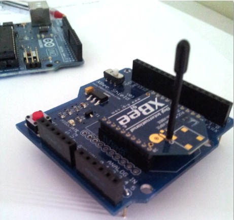
Most of the Android/Processing code used so far has depended on a Bluetooth Device being discoverable. Our ultimate aim it to connect to a Bluetooth Shield on an Arduino UNO or compatible board such as the Freetronics Eleven. The following sketch was essentially taken from one of my previous posts (
here), however, I have stripped it down to the bear essentials so that it will only be discoverable, and will not send or receive data. I will provide this functionality later. I just wanted to show you the essential bits to establish the connection to the Shield.
ARDUINO Sketch 1: Bluetooth Pair and Connect1
2
3
4
5
6
7
8
9
10
11
12
13
14
15
16
17
18
19
20
21
22
23
24
25
26
27
28
29
30
31
32
33
34
35
36
37
38
39
40
41
42
43
44
45
46
47
48
49
50
51
52
53 | /* This project combines the code from a few different sources.
This project was put together by ScottC on the 22/03/2013
http://arduinobasics.blogspot.com/
Bluetooth slave code by Steve Chang - downloaded from :
http://www.seeedstudio.com/wiki/index.php?title=Bluetooth_Shield
This sketch does nothing more than setup bluetooth
connection capabilities. It does not send or receive data.
*/
#include <SoftwareSerial.h> //Software Serial Port
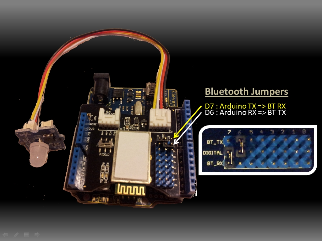
#define RxD 6 // This is the pin that the Bluetooth (BT_TX) will transmit to the Arduino (RxD)
#define TxD 7 // This is the pin that the Bluetooth (BT_RX) will receive from the Arduino (TxD)
#define DEBUG_ENABLED 1
SoftwareSerial blueToothSerial(RxD,TxD);
/*----------------------SETUP----------------------------*/ void setup() {
Serial.begin(9600); // Allow Serial communication via USB cable to computer (if required)
pinMode(RxD, INPUT); // Setup the Arduino to receive INPUT from the bluetooth shield on Digital Pin 6
pinMode(TxD, OUTPUT); // Setup the Arduino to send data (OUTPUT) to the bluetooth shield on Digital Pin 7
pinMode(13,OUTPUT); // Use onboard LED if required.
setupBlueToothConnection(); //Used to initialise the Bluetooth shield
}
/*----------------------LOOP----------------------------*/ void loop() {
digitalWrite(13,LOW); //Turn off the onboard Arduino LED
}
//The following code is necessary to setup the bluetooth shield ------copy and paste----------------
void setupBlueToothConnection()
{
blueToothSerial.begin(38400); //Set BluetoothBee BaudRate to default baud rate 38400
blueToothSerial.print("\r\n+STWMOD=0\r\n"); //set the bluetooth work in slave mode
blueToothSerial.print("\r\n+STNA=SeeedBTSlave\r\n"); //set the bluetooth name as "SeeedBTSlave"
blueToothSerial.print("\r\n+STOAUT=1\r\n"); // Permit Paired device to connect me
blueToothSerial.print("\r\n+STAUTO=0\r\n"); // Auto-connection should be forbidden here
delay(2000); // This delay is required.
blueToothSerial.print("\r\n+INQ=1\r\n"); //make the slave bluetooth inquirable
Serial.println("The slave bluetooth is inquirable!");
delay(2000); // This delay is required.
blueToothSerial.flush();
}
|
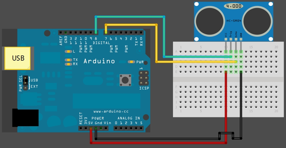
Please make sure to setup the Bluetooth jumpers as per the picture below, otherwise you will not have much luck with the sketch above.
Well that brings us to the end of part TWO.
PART THREEIn
part three we will attempt to actually send some data from the Android phone to the Arduino via Bluetooth, and vice versa. This will be when the real fun starts.
or GO BACKClick on the link if you missed
PART ONE