Nextion Enhanced Stepper Motor Piano Project
Introduction
Nextion is a programmable human machine interface (HMI) that can be customized and designed to simplify the interaction between you and your project.
This Nextion Enhanced module (NX4827K043) with a resistive touch screen display, has some additional features not seen in previous traditional versions of the Nextion series.
- A built in real time clock (RTC)
- Accessible flash memory (32MB)
- GPIO functionality
- Faster clock speed
Before you connect the Nextion Enhanced module to your project, you need to design your interface with the free Nextion Editor. The editor can be downloaded here.
In this project, I will be designing a simple dynamic interface, which will allow me to interact with a stepper motor in two different ways.
The first interface will let me control the direction and speed of the stepper motor through the use of a simple GUI. I will have left and right arrows for the direction, and up and down arrows for the speed. I will also map the Expansion board to this interface for a more tactile experience.
The second interface will be more musical in nature. I will design a functional “Stepper motor piano” that will allow me to play simple songs using the rotational sounds of the stepper motor. This concept is not new, but I will show you how easy it is to make.
Parts Required:
- Arduino UNO (or compatible board)
- Nextion Enhanced NX4827K043 from iTead Studio (more info here)
- Nextion Expansion board for Nextion Enhanced display
- Micro SDHC Card
- SD Card Reader/Writer - to transfer files from computer to SDHC card
- Breadboard
- Stepper Motor (42BYGHM809) - (Here is the datasheet)
- 100 uF Capacitor
- Duinotech Stepper Motor Driver (L298) - [JayCar part# XC4492] (Here is the datasheet).
- External Power supply - e.g. Regulated Lab Power Supply
Project Scope
My project will show a splash screen when the project is powered up. After 3 seconds, the first interface will display.
The first interface will have 4 arrows:
- Left and Right arrows for the stepper motor direction of rotation
- Up and down arrows to increase/decrease stepper motor rotational speed
- Next Page button – to jump to the next interface
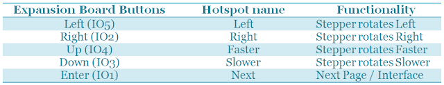
Each arrow/button on the first interface will be mapped to a specific button on the expansion board. Eg.
- Left/Right arrow is mapped to Left/Right button
- Up/Down arrow is mapped to Up/Down button
- Next page button is mapped to Enter button on the expansion board
The second interface will look like a piano on the Nextion Enhanced display. Each key on the piano will transmit a specific and unique number to the Arduino.
The specific number received by the Arduino will allow it to set the speed of stepper motor which will ultimately affect the frequency of sound it produces. Therefore when the “C” key is pressed on the Nextion display, the stepper motor will rotate at a frequency that sounds like a “C” note.
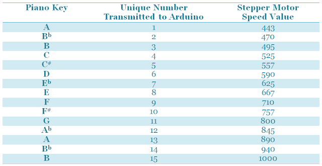
The stepper motor speeds can be determined by tuning the motor to specific notes using the first interface and an iPhone app called Tuner T1 Free".
If you plan to replicate this project, you will need to determine the relevant speeds of your own stepper motor, and substitute your values into the Arduino code later on in this tutorial.
Create a New Project
The first step is to create the interfaces in the Nextion Editor on your PC. You can download the Nextion Editor here.. Load up the Nextion Editor and create a new project.
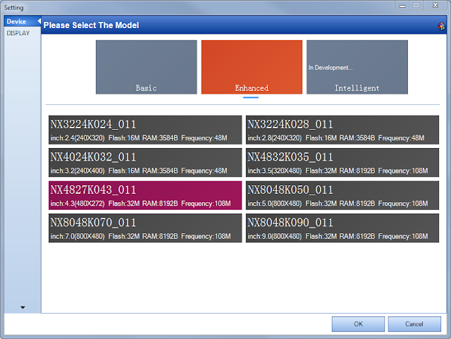
When you start a new project, you need to make sure that you select the correct Nextion device from the available options.
I am using the “Nextion Enhanced NX4827K043” device.
- Select File → New
- Select a name for the project and save it to a suitable place on the hard drive
- Select the appropriate Nextion device from the available options
- My device has a screen size of 480 x 272 pixels
Project Resources
You need to import all of the resources (eg. pictures and fonts) into your project, and then design the interface to suit your specific needs.
Fonts
I will not be using any fonts in my project, but if you wanted to write any text to the display, you will need to generate a font in the Nextion Editor.
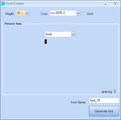
- Tools → Font Generator
- Select the Height of the Font (eg. 16)
- Select the Font code type (eg. iso-8859-2)
- Select if you want it to be in Bold or not
- Choose the Font you want to use (eg. Arial)
- Choose the spacing (eg. 0)
- And finally give this Font a unique name (e.g. Arial_16)
- Push the “Generate Font” button on the bottom right of the window
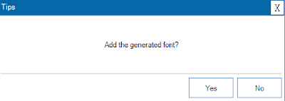
Once you press the Generate Font button, it will get you to save the font using a *.zi extension, and will automatically ask you if you would like to “Add the generated font?” to the project. If you are happy with the font, and would like to use this font in your project, then select “Yes”, otherwise select “No” and start again.
You cannot add any text to your project until you have imported or added a font. All of your project fonts will be displayed in the fonts window.
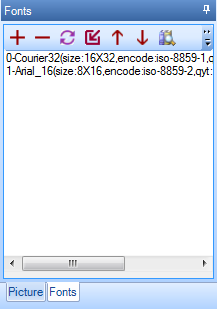
Each font will automatically be indexed, so that you can reference the font programmatically if required. In fact all resources that you add to your project are assigned a number and incremented by one for every resource added. For some resources, you can see this number to the left of the item. E.g. In the picture above, the Courier Font has an index of 0, whereas the Arial font has an index of 1. If you delete a resource, the index number may change for that item.
Pictures
As I said before, I will not be using any fonts for my project because the words on the screen will not be changing in any way. I can get away with designing a “Picture” and importing that into the project. I will need 3 pictures for my project.
- Splash screen
- Stepper Motor Controller
- Stepper Motor Piano
On the Nextion Enhanced NX4827K043 device, each picture must be
- 480 x 272 pixels in size
We will now import the following pictures into the Nextion Editor so that we can use them in the project.
In the bottom left hand corner of the Nextion editor is the “Fonts and Picture” resource window:
- Select the Picture tab
- Then select the “+” icon
- This will open a dialog box to allow you to select the picture(s) to add to the project. You can select more than one picture to import.
I imported the following pictures from my computer:
Splash Screen

Interface 1: Stepper Motor Controller
Interface 2: Stepper Motor Piano
Creating the GUI
Pages
Every resource will get an ID based on the order it is added, and each resource will automatically get a name. You can change the name of the resource or object, but you cannot edit the ID.
Three pages will be designed to meet the criteria described above.
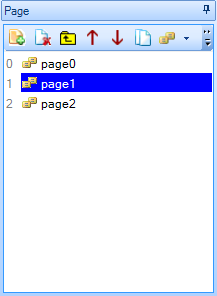
To add a page, you simply select the “Add” icon from the “page window”. And keep adding pages until you have a total of 3 pages (page0, page1 and page2).
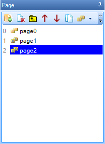
Page 0 - Splash Screen
When the Nextion is powered up, the splash screen will be displayed for 3 seconds before it shows the Stepper Motor Controller screen. I used the following steps to create the splash screen.
- Add the splash screen picture to page0
- Select “page0” from the Page window
- Select “Picture” from the Toolbox window
- Double-click the “pic” attribute from the Attribute window
- Select the splash screen image from the list
- Press the OK button
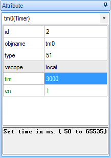
- Add a Timer to page0
- Select Timer from the Toolbox window
- Change the “tim” attribute from 400 to 3000 in the Attribute window
- Enter “page page1” in the User code section of the Timer Event(0)
This timer event will make the Nextion jump to page1 after 3 seconds.
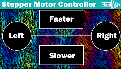
Page 1 - Stepper Motor Controller
This page is designed to control the direction and speed of the stepper motor.
There will be two buttons for the direction (Left and Right), and two buttons for the speed (Faster and Slower). And one more button to jump to the next page (i.e. the Stepper Motor Piano page). These buttons will also be mapped to the Nextion expansion board. The tactile buttons of the expansion board will provide an alternative method of controlling the motor.
- Add the Stepper Motor Controller picture to page1
- Select “page1” from the Page window
- Select “Picture” from the Toolbox window
- Double-click the “pic” attribute from the Attribute window
- Select the “Stepper Motor Controller” image from the list
- Press the OK button
- Add Hotspots over each button on the Stepper Motor Controller image
- Select “Hotspot” from the Toolbox window
- Drag and resize the Hotspot so that it covers the “Left” button
- This is the area that will respond to “Left button” presses.
- It will be transparent when uploaded to the Nextion board
- Select the “Touch Press Event” tab in the Event window
- Un-Check the “Send Component ID” checkbox
- Type the following code into the “User Code” Section of the Event window:
- print “L”
- Change the object name of the hotspot to “Left” using the following process:
- Select objname from the attribute window and change the text from “m0” to “Left”
- It is not compulsory to change the hotspot object name; however it will help later on.
- Repeat steps 2a-2f for each of the other buttons in the following order and as per the table below
- Right
- Faster
- Slower
- Next
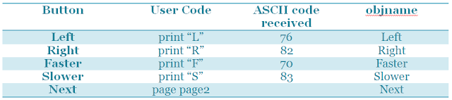
The decimal ASCII code for the letter “L” is 76, hence when the Nextion Enhanced display sends the letter L to the Arduino using the print “L” command, the Arduino will receive the number 76. When the right button is pressed, it will receive the number 82, and so on.
The “Next” button does not transmit anything to the Arduino, it is simply there to jump to the next interface on the Nextion Enhanced display, hence the reason why the user code is different for that button.
- Map the buttons to the Expansion board
- Select “page0” and then “page1” from the Page window
- Select the “Preinitialize Event” tab from the Event window
- Enter the following code into the “User Code” field of the Preinitialize Event tab:
- cfgpio 5,1,Left
- cfgpio 2,1,Right
- cfgpio 4,1,Faster
- cfgpio 3,1,Slower
- cfgpio 1,1,Next
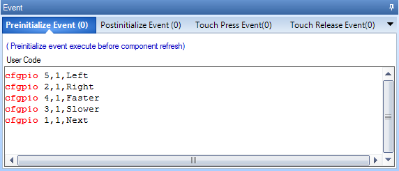
Please note: There is one space between cfgpio and the number next to it, but there are no other spaces on each line. If you introduce extra spaces, it will not compile.
This code maps the buttons on the expansion board to the hotspot objects on page1. For example, when the Left button (IO5) on the expansion board is pressed, it simulates the actions or events associated with hotspot m0/Left. In this case it will send a value of “L” (76) to the Arduino.
The IO number is marked within brackets on the expansion board.
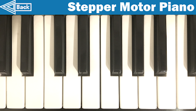
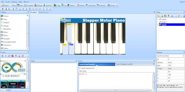
Page 2 - Stepper Motor Piano
This interface will be designed to look like a piano, and will allow me to control the stepper motor such that it produces a note in the same key as the one I press on the Nextion display. The stepper motor will produce the note by rotating at a specific frequency.
- Add the Stepper Motor Piano picture to page2
- Select “page2” from the Page window
- Select “Picture” from the Toolbox window
- Double-click the “pic” attribute from the Attribute window
- Select the “Stepper Motor Piano” image from the list
- Press the OK button
- Add Hotspots over each key on the Stepper Motor Piano image
- Select “Hotspot” from the Toolbox window
- Drag and resize the Hotspot so that it covers the the “A” key.
- This is the area that will respond to “A-key” presses.
- It will be transparent when uploaded to the Nextion board
- Select the “Touch Press Event” tab in the Event window
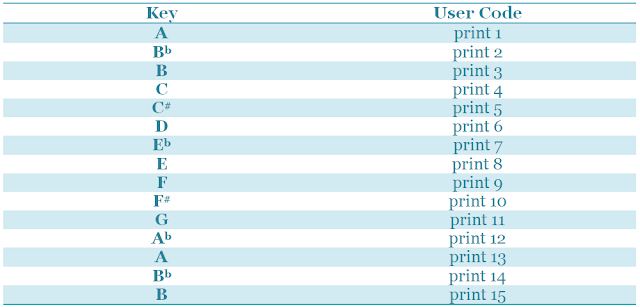
- Type the following into the “User Code” section
- print 1
- Repeat steps 2a-2d for each of the other keys as per the table below
When the specific key is pressed, the Nextion Enhanced board will transmit the printed number, followed by three 0x00 values. The terminating values can be ignored.
- The “Back” button will allow me to jump back to the previous interface on the Nextion Enhanced board.
- Create a hotspot for the back button using the following process:
- Select Hotspot from the Toolbox window
- Move/Resize the hotspot over the “Back” button
- Select the Event window
- Make sure the “Touch press event” tab is selected
- Type: page page1 into the User Code section
- Create a hotspot for the back button using the following process:
Debugging
The good thing about the Nextion Editor, is that you can test out the interface functionality before uploading it to the board.

- Save the project by pressing the save button on the task bar
- Then press the compile button
- Then press the debug button.
A Nextion emulator window will appear. This window should respond in the same manner as Nextion module after the Nextion file is uploaded to the board. This emulator is a great way to test out your interface and to make sure it looks and works as expected. Once I was happy with the interface(s), I transferred the compiled Nextion file onto an SD card:
- Press the compile button
- File → Open Build Folder
- Select the *.tft file with the same name as that of the project
- Copy it to a micro SDHC card
- Insert the SDHC card into the SD card slot on the Nextion display
- Power up the Nextion board
Wait for the file to flash the Nextion board, and you should see a message that looks like this:
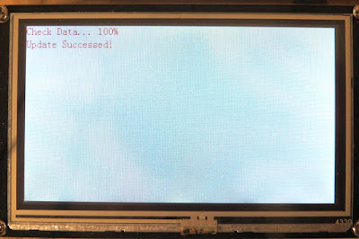
The next step is to power off the Nextion board, and remove the SDHC card.
ARDUINO SETUP
The Nextion Enhanced display is ready, and now it is the Arduino’s turn. The Arduino is programmed to receive Serial messages from the Nextion Enhanced display and control the stepper motor based on the letters or numbers received. The unique letters or numbers being transmitted from the Nextion board, allow the Arduino to understand what button is being pressed, and it uses those numbers or letters to control the flow of code in order to perform specific stepper motor actions.
Arduino Libraries and IDE
The Arduino IDE can be downloaded from this site.
The SoftwareSerial library is used to enable Serial communication between the Arduino and the Nextion Enhanced display.
The AccelStepper library is used to simplify the process of stepper motor control.
ARDUINO CODE:
Here is the Arduino Code for this project:
I set up a maximum and minimum speed for the motors, and some pre-defined keys. It is possible to “tune” the motor using the first interface of the Nextion display. You can do this by making the motor turn faster or slower until you reach the desired key.
I used the “Tuner T1 Free” app from the iTunes app store to identify WHEN the motor was producing a note in key.
When the motor was producing a specific note, I would write down the stepper motor speed that was printed to the Serial monitor window. Every time the motor speed is increased or decreased, the Arduino code prints the speed to the serial monitor window. I then use these speeds to update the notes[] array in the Arduino code.
The notes[] array holds the stepper motor speeds that correspond to the individual notes on the piano. The Nextion display essentially sends the index number of the note to play from the notes array on the Arduino, thereby simplifying the code required to spin the motor at 16 different speeds.
Hooking it up:
With all boards powered off, the next step is to make all of the necessary hardware connections to the Arduino. There are two major sections to consider,
- The Stepper motor driver and motor
- The Nextion Enhanced board
You need to ensure that you use an external power source to power both the stepper motor and the Nextion Enhanced board. The stepper motor driver board itself was powered by the Arduino without any problems, but the actual stepper motor will need an external power supply. The Nextion Enhanced board also needs an external power supply because it requires more current than the Arduino can safely provide.
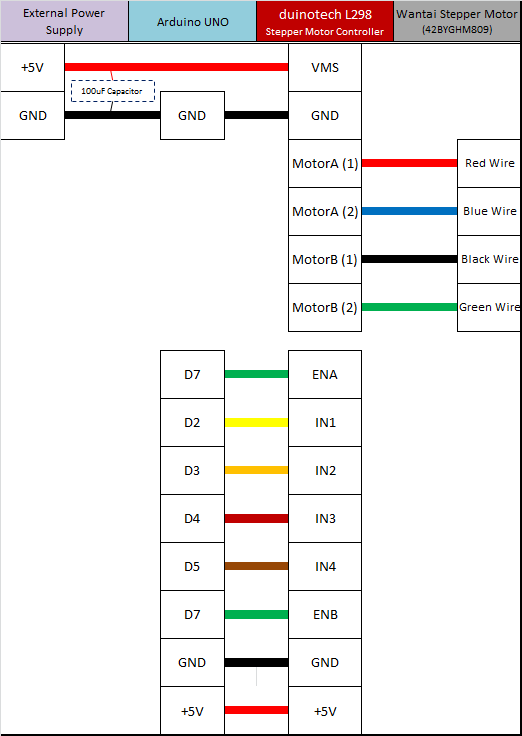
Here is how you would connect the Arduino to the Stepper motor driver board and associated stepper motor.


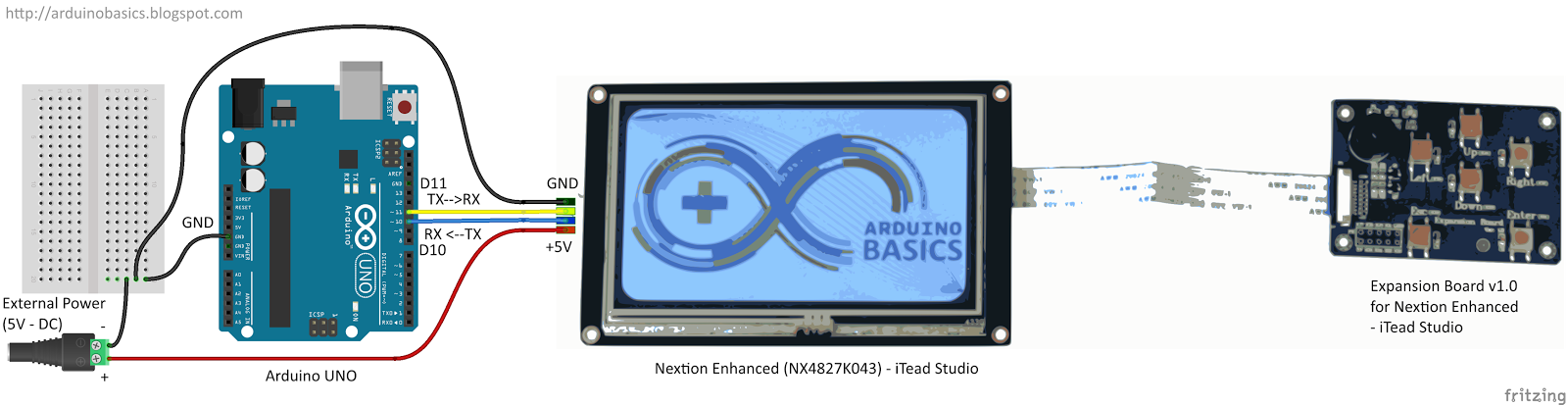
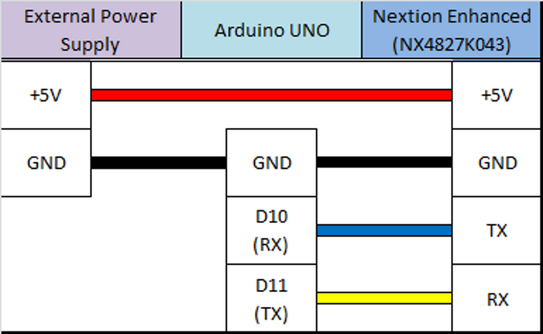
And this is how you would connect the Arduino to the Nextion Enhanced display
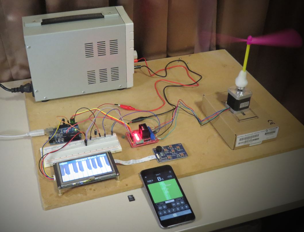
And this is what it looked like when I put it all together:

Make note of the external power supply used. I made sure that I had a large enough power supply to handle the power requirements of the project, and utilized the relevant datasheets to help me identify those requirements. If you plan to replicate this project, make sure you take into consideration the specific power requirements of your motor, your motor driver and your Nextion display. The Arduino can only supply 400mA of current from the 5V pin.
With everything hooked up, I powered up the Nextion display, then powered up the Arduino. The stepper motor starts spinning automatically. I used the first interface to change the direction and/or speed of the motor. Please note the maximum and minimum speeds set up in the Arduino code.
I then used the Next button to jump to the second interface on the Nextion Enhanced display. The second interface looks like a piano. And when I press a key on the piano display, the motor changes speed to match the note I pressed.
Voila !! The stepper motor piano is born !!
I played a number of simple tunes on the Stepper motor piano and was surprised how well it worked. Very clever !!
Concluding comments
This project is relatively simple, but stepper motors can be tricky to set up and tune. Nothing a bit of determination cannot fix.
This project was a lot of fun. If you plan to replicate this project, I would be interested to see your versions, or just knowing if this helped you in any way.

This project would not have been possible without the collaborative efforts of iTead Studio. Their Nextion Enhanced display has a lot more to offer than what I have shown you here. But hopefully this tutorial gives you some insight into the power of such a display, and perhaps how it could improve the project you are currently working on. The only thing I did not like was the power requirements. I would have preferred something within Arduino power supply limits. Nevertheless, I am very happy with the Nextion Enhanced display, and would recommend it to anyone looking for a Human Machine interface to include in their project. You can see how simple it was to create TWO interfaces for my project, and I only scratched the surface.