

Wise Clock 4 with Bluetooth
Another thing that was supposed to be easy, but it wasn't: Arduino communicating with Windows XP through Bluetooth.
Like everybody else, I purchased the cheap and ubiquitous Bluetooth module from dealextreme.
I soldered it myself on the XBee-footprinted PCB (bare BTBee from IteadStudio), for a total price of about $8 (compare that to at least $15 as these Bluetooth XBees go for).
Without knowing much about Bluetooth, I plugged this new "BTBee" module in Wise Clock 4 expecting it to be "discovered" by XP (which has an USB Bluetooth dongle). Discovered it was: the name "linvor" appeared in the list of BT devices, with two serial ports attached to it.
Communication between XP and BT module is performed through the serial ports, I figured. Tried CoolTermWin, HyperTerminal, Putty, on both ports, nothing seemed to work. Time to read the documentation (which always reminds me of that joke). I learned that others had similar problems, and some have solved them by installing new BT drivers. The best advice came from this post. Putty did not work for me, so I stuck with what I had, namely HyperTerminal.
So here is my own step-by-step tutorial on how to make an Arduino communicate with Windows XP via a Bluetooth module.
Note: From the Bluetooth perspective, Wise Clock 4 I used for my testing is similar to Arduino.
1. Upload this simple sketch that "echos" what it reads from Bluetooth and also broadcasts a message periodically. The communication between Arduino and the BT module is serial, with a baud rate of 9600, according to the documentation.
#if ARDUINO < 100
#include
#else
#include
#endif
Serial.begin(9600);
}
void loop()
{
while (Serial.available())
{
// get char from bluetooth;
char inChar = (char) Serial.read();
// output it back, between brackets;
Serial.print('[');
Serial.print(inChar);
Serial.print(']');
}
// broadcast message;
Serial.print("millis() from Arduino: ");
Serial.println(millis());
delay(2000);
}
2. Power Arduino, with the BT module connected, and let it run the sketch.
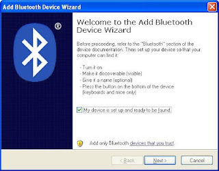
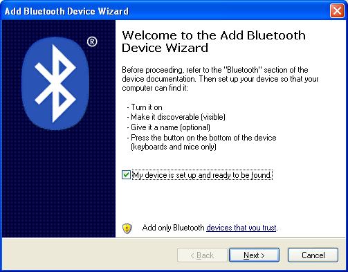
3. Make the BT module (on the Arduino) visible to XP, by adding it to the list of Bluetooth devices. For this, click on the "Bluetooth Devices" icon in the tray (bottom right corner of the XP's desktop). You will see this box.
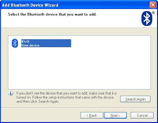
Next, you will see the BT device added to the list, under the name "linvor".
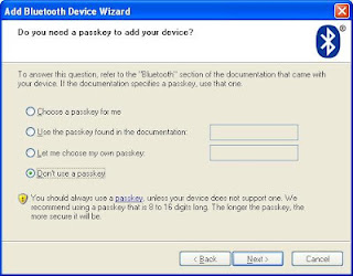
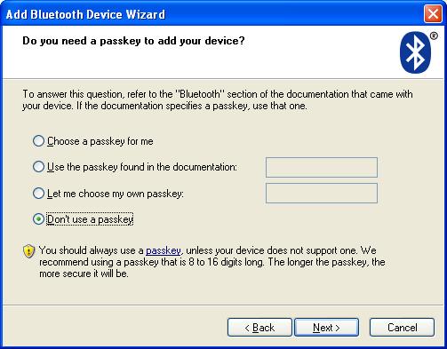
Then select the last option, "Don't use a passkey". Although it makes little sense at this point (since you know that the passkey is 1234, according to the documentation), it is very important to not use a passkey here.
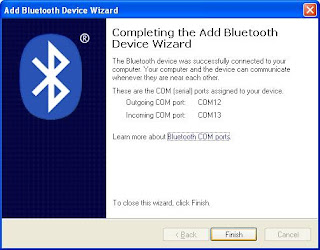
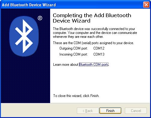
The last step of the wizard shows the two ports that have been added. Write down the "Outgoing COM port", since this is the one we will be using for communication (step 4).
4. Open HyperTerminal to establish the 2-way communication between XP and Arduino, via Bluetooth.
Select, from the list, the COM port specified as "outgoing" for the BT device.

Next, you will be shown this pop-up.

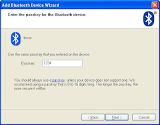
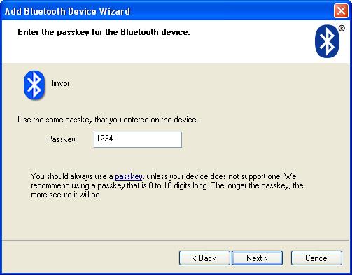
After you click on it, you are prompted to enter the passkey, the one you (reluctantly) skipped in the process of setting up the BT device. Type "1234", as specified in the BT module documentation.
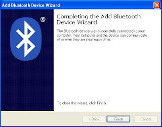
After hitting "Next", you are shown this last confirmation box.
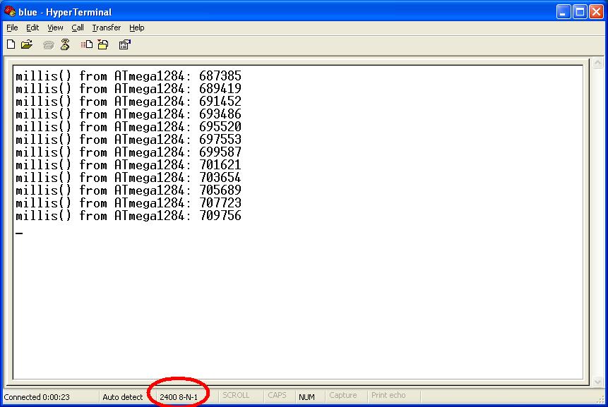
In the same time, the HyperTerminal starts displaying the message coming from Arduino.
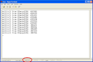
Note that, when the COM port was opened in Auto mode, no parameters (bad rate etc) being specified.
Interestingly, after the communication is established, the baud rate is reported as 2400 (for some unexplained reason).
You can also type characters in the HyperTerminal and they will be echoed back (between brackets) by Arduino.
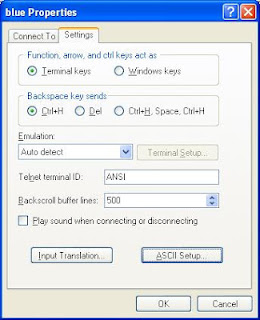
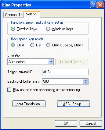
Optionally, if you want to see what you typed (before the echoing from Arduino takes place), you can enable local echo, by selecting "Properties", then "ASCII Setup".

Once the communication between XP (HyperTerminal) and Arduino is established via Bluetooth, the "Status" LED (if you have it soldered) is on continuously. When the BT module is not communicating, the "Status" LED is blinking at a frequency of about 2Hz.
The next time a HyperTerminal session is opened, XP remembers the BT device and the communication params (ports, passkey) and does not ask to set it up again. (I guess that's why it is called "pairing", although this word does not appear anywhere in the process.)
Time to write some serious applications using Bluetooth:)
Like everybody else, I purchased the cheap and ubiquitous Bluetooth module from dealextreme.
I soldered it myself on the XBee-footprinted PCB (bare BTBee from IteadStudio), for a total price of about $8 (compare that to at least $15 as these Bluetooth XBees go for).
Without knowing much about Bluetooth, I plugged this new "BTBee" module in Wise Clock 4 expecting it to be "discovered" by XP (which has an USB Bluetooth dongle). Discovered it was: the name "linvor" appeared in the list of BT devices, with two serial ports attached to it.
Communication between XP and BT module is performed through the serial ports, I figured. Tried CoolTermWin, HyperTerminal, Putty, on both ports, nothing seemed to work. Time to read the documentation (which always reminds me of that joke). I learned that others had similar problems, and some have solved them by installing new BT drivers. The best advice came from this post. Putty did not work for me, so I stuck with what I had, namely HyperTerminal.
So here is my own step-by-step tutorial on how to make an Arduino communicate with Windows XP via a Bluetooth module.
Note: From the Bluetooth perspective, Wise Clock 4 I used for my testing is similar to Arduino.
1. Upload this simple sketch that "echos" what it reads from Bluetooth and also broadcasts a message periodically. The communication between Arduino and the BT module is serial, with a baud rate of 9600, according to the documentation.
#if ARDUINO < 100
#include
#else
#include
#endif
void setup()
{Serial.begin(9600);
}
void loop()
{
while (Serial.available())
{
// get char from bluetooth;
char inChar = (char) Serial.read();
// output it back, between brackets;
Serial.print('[');
Serial.print(inChar);
Serial.print(']');
}
// broadcast message;
Serial.print("millis() from Arduino: ");
Serial.println(millis());
delay(2000);
}
2. Power Arduino, with the BT module connected, and let it run the sketch.
3. Make the BT module (on the Arduino) visible to XP, by adding it to the list of Bluetooth devices. For this, click on the "Bluetooth Devices" icon in the tray (bottom right corner of the XP's desktop). You will see this box.
Next, you will see the BT device added to the list, under the name "linvor".

Then select the last option, "Don't use a passkey". Although it makes little sense at this point (since you know that the passkey is 1234, according to the documentation), it is very important to not use a passkey here.
The last step of the wizard shows the two ports that have been added. Write down the "Outgoing COM port", since this is the one we will be using for communication (step 4).
4. Open HyperTerminal to establish the 2-way communication between XP and Arduino, via Bluetooth.
Select, from the list, the COM port specified as "outgoing" for the BT device.
Next, you will be shown this pop-up.

After you click on it, you are prompted to enter the passkey, the one you (reluctantly) skipped in the process of setting up the BT device. Type "1234", as specified in the BT module documentation.
After hitting "Next", you are shown this last confirmation box.

In the same time, the HyperTerminal starts displaying the message coming from Arduino.
Note that, when the COM port was opened in Auto mode, no parameters (bad rate etc) being specified.
Interestingly, after the communication is established, the baud rate is reported as 2400 (for some unexplained reason).
You can also type characters in the HyperTerminal and they will be echoed back (between brackets) by Arduino.
Optionally, if you want to see what you typed (before the echoing from Arduino takes place), you can enable local echo, by selecting "Properties", then "ASCII Setup".
Once the communication between XP (HyperTerminal) and Arduino is established via Bluetooth, the "Status" LED (if you have it soldered) is on continuously. When the BT module is not communicating, the "Status" LED is blinking at a frequency of about 2Hz.
The next time a HyperTerminal session is opened, XP remembers the BT device and the communication params (ports, passkey) and does not ask to set it up again. (I guess that's why it is called "pairing", although this word does not appear anywhere in the process.)
Time to write some serious applications using Bluetooth:)


