Arduino-compatible VFD modular clock from Akafugu
There aren't many VFD clock kits out there that are software-compatible with Arduino (and by that I mean the "Arduino sketch" being compilable in Arduino IDE and uploadable through USB-FTDI).
Most of these kits come with the microcontroller pre-programmed, so they can be built quickly and easily, with minimal effort (totally understandable instant gratification; nobody wants to end up with an expensive dud). Upgrading the software usually requires familiarity with the microcontroller toolchain (compile-build-flash), plus an ISP programmer. (Note: The only processor I am familiar with is AVR/Atmega.)
I was going to build myself an Arduino-based VFD clock, one that can take a sketch through the FTDI cable. Instead of starting from scratch (choosing a schematic, making the board etc), I decided to try one of the only 2 open-source VFD clock kits I found that are based on Atmega processor and :
I settled for the VFD modular clock because the Akafugu people offered me the pair of PCBs in their kit (for a very reasonable $19, shipping included) and also because I already had most of the parts, including the two SMDs (that come pre-soldered in the kit: ATmega328 and HV5812) and the IV-17 VFD tubes.

I built the clock following their great assembling instructions, but, as you will see, not without hitting a few stumbling blocks on the way.
I should clarify that this post is not a review of the VFD modular clock kit (since I did not have the kit), but just a record of my observations. It was my choice to not use the kit, thus forcing myself to try to understand the schematic and the software.
Since my goal was to make the VFD modular clock Arduino-compatible, I was aware of the challenges awaiting me:
- burning the bootloader for ATmega328 with internal 8MHz oscillator;
- connecting a makeshift FTDI header;
- adapting the software to work in Arduino IDE;
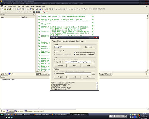
Once I figured out the fuses, burning the bootloader was straightforward. For this purpose I created this section in boards.txt:
intclock328.name= ATmega328 Internal clock 8MHz
intclock328.upload.protocol=stk500
intclock328.upload.maximum_size=30720
intclock328.upload.speed=57600
intclock328.bootloader.low_fuses=0xE2
intclock328.bootloader.high_fuses=0xDA
intclock328.bootloader.extended_fuses=0x05
intclock328.bootloader.path=atmega
intclock328.bootloader.file=ATmegaBOOT_168_atmega328_pro_8MHz.hex
intclock328.bootloader.unlock_bits=0x3F
intclock328.bootloader.lock_bits=0x0F
intclock328.build.mcu=atmega328p
intclock328.build.f_cpu=8000000L
intclock328.build.core=arduino
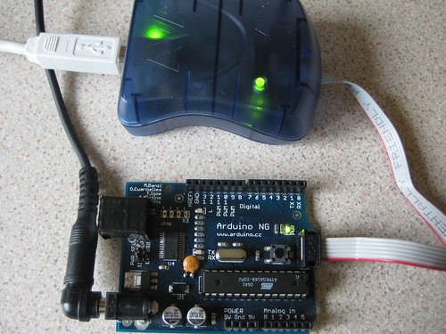
Then I checked that the bootloader works, by uploading a simple sketch that outputs on D9 (which is connected to the buzzer). Before doing this, I had to connect the FTDI breakout to the board. Luckily (more probably intentionally), all of the required pins (Rx, Tx, Vcc, Gnd, Rst) are broken out on the female header, so just using wires worked, as shown in the next photo. This is not a nice solution though, since the top board (with the VFDs) needs to be removed before every sketch upload. (Hopefully the Akafugu team will also include an FTDI header in the next revision.)

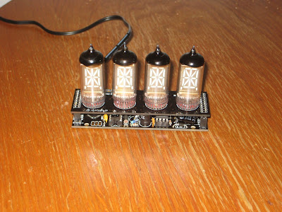
After I soldered all the parts on the base board, I realized the biggest problem of them all: some parts (sourced by me, and obviously of different size than those in the kit) stuck well above the two lateral headers, so the display shield (upper board) could not be plugged in the base board. Almost a showstopper at this point. The solution was to replace the tall 330uF/16V capacitor, bend both 47uF capacitors sideways, replace the 330uF/50V with a pair of thinner 100uF, push both inductors as much into the PCB as possible, then cut the top plastic wrapping on one of them. These, combined with the male headers not being flush to the display board when I soldered them, did the trick. I managed to have the clock looking as intended by its creators (if you don't look too closely), as shown in the next photo.
The Akafugu designers tried to minimize the size of the clock, leaving little room for flexibility (that is, ability to use a broader range of components, of different sizes eventually). The sizes for the chosen components (especially the capacitors and the inductors) are really unique, any deviation would lead to the boards not fitting together.
Using (smaller) SMD components would not be a good solution, since these would also need to be pre-soldered (or otherwise potential non-SMD-soldering clients would be excluded). The only compromise I can think of is enlarging the base board a little bit, keeping in mind that this 4-tube version is the smallest of the display boards, all others extending laterally beyond both sides of the base board.
And finally, the last challenge: the software. I started from the original C code published here. This was written for the avr-gcc compiler and produces a hex file, which is then flashed onto the processor (no bootloader needed, nor provided) using an ISP programmer.
I changed the code (available here), mostly cosmetically, to compile with Arduino 1.0. It does not require any other external libraries and it includes its own I2C/Wire functions (does not use Arduino's Wire library).
In the end, I have an Arduino-compatible Akafugu VFD modular clock that looks just like the original one (I need to add the spacers though).


Most of these kits come with the microcontroller pre-programmed, so they can be built quickly and easily, with minimal effort (totally understandable instant gratification; nobody wants to end up with an expensive dud). Upgrading the software usually requires familiarity with the microcontroller toolchain (compile-build-flash), plus an ISP programmer. (Note: The only processor I am familiar with is AVR/Atmega.)
I was going to build myself an Arduino-based VFD clock, one that can take a sketch through the FTDI cable. Instead of starting from scratch (choosing a schematic, making the board etc), I decided to try one of the only 2 open-source VFD clock kits I found that are based on Atmega processor and :
I settled for the VFD modular clock because the Akafugu people offered me the pair of PCBs in their kit (for a very reasonable $19, shipping included) and also because I already had most of the parts, including the two SMDs (that come pre-soldered in the kit: ATmega328 and HV5812) and the IV-17 VFD tubes.

I built the clock following their great assembling instructions, but, as you will see, not without hitting a few stumbling blocks on the way.
I should clarify that this post is not a review of the VFD modular clock kit (since I did not have the kit), but just a record of my observations. It was my choice to not use the kit, thus forcing myself to try to understand the schematic and the software.
Since my goal was to make the VFD modular clock Arduino-compatible, I was aware of the challenges awaiting me:
- burning the bootloader for ATmega328 with internal 8MHz oscillator;
- connecting a makeshift FTDI header;
- adapting the software to work in Arduino IDE;
Once I figured out the fuses, burning the bootloader was straightforward. For this purpose I created this section in boards.txt:
intclock328.name= ATmega328 Internal clock 8MHz
intclock328.upload.protocol=stk500
intclock328.upload.maximum_size=30720
intclock328.upload.speed=57600
intclock328.bootloader.low_fuses=0xE2
intclock328.bootloader.high_fuses=0xDA
intclock328.bootloader.extended_fuses=0x05
intclock328.bootloader.path=atmega
intclock328.bootloader.file=ATmegaBOOT_168_atmega328_pro_8MHz.hex
intclock328.bootloader.unlock_bits=0x3F
intclock328.bootloader.lock_bits=0x0F
intclock328.build.mcu=atmega328p
intclock328.build.f_cpu=8000000L
intclock328.build.core=arduino

After I soldered all the parts on the base board, I realized the biggest problem of them all: some parts (sourced by me, and obviously of different size than those in the kit) stuck well above the two lateral headers, so the display shield (upper board) could not be plugged in the base board. Almost a showstopper at this point. The solution was to replace the tall 330uF/16V capacitor, bend both 47uF capacitors sideways, replace the 330uF/50V with a pair of thinner 100uF, push both inductors as much into the PCB as possible, then cut the top plastic wrapping on one of them. These, combined with the male headers not being flush to the display board when I soldered them, did the trick. I managed to have the clock looking as intended by its creators (if you don't look too closely), as shown in the next photo.

The Akafugu designers tried to minimize the size of the clock, leaving little room for flexibility (that is, ability to use a broader range of components, of different sizes eventually). The sizes for the chosen components (especially the capacitors and the inductors) are really unique, any deviation would lead to the boards not fitting together.
Using (smaller) SMD components would not be a good solution, since these would also need to be pre-soldered (or otherwise potential non-SMD-soldering clients would be excluded). The only compromise I can think of is enlarging the base board a little bit, keeping in mind that this 4-tube version is the smallest of the display boards, all others extending laterally beyond both sides of the base board.
And finally, the last challenge: the software. I started from the original C code published here. This was written for the avr-gcc compiler and produces a hex file, which is then flashed onto the processor (no bootloader needed, nor provided) using an ISP programmer.
I changed the code (available here), mostly cosmetically, to compile with Arduino 1.0. It does not require any other external libraries and it includes its own I2C/Wire functions (does not use Arduino's Wire library).
In the end, I have an Arduino-compatible Akafugu VFD modular clock that looks just like the original one (I need to add the spacers though).