

4-Digit Seven Segment TM1637 Display interfacing with arduino
Hello Arduino Lovers,
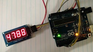
In this post, I am going to interface 4-digit seven segment display with arduino. It's TM1637 based display and it just requires 4-pins. And it's better than conventional 4-digid SSD since that requires 12 (8+4) output pins. So, it saves our pin. As MCU have limited I/Os it's very useful.
The pins are as follows:
CLK, DIO, VCC and GND.
It's 2-wire serial communication and it's different from I2C communication.
The connections are as follows:
In this post, I am going to interface 4-digit seven segment display with arduino. It's TM1637 based display and it just requires 4-pins. And it's better than conventional 4-digid SSD since that requires 12 (8+4) output pins. So, it saves our pin. As MCU have limited I/Os it's very useful.
The pins are as follows:
CLK, DIO, VCC and GND.
It's 2-wire serial communication and it's different from I2C communication.
 |
| 4-Digit SSD |
Display Arduino
CLK Pin no. 2
DIO Pin no. 3
VCC +5 V
GND GND
In order, to send proper data, we have pass start commands , then data and finally stop commands. We are using functions for each of them.

Source Code:
/*
Program for displaying counting from 0-9999
www.funwidelectronics.blogspot.in
This source code is modified from:
https://blog.3d-logic.com/2015/01/21/arduino-and-the-tm1637-4-digit-seven-segment-display/
Thanks for the code
*/
// Module connection pins (Digital Pins)
#define clk 2
#define data 3
uint8_t digits[] = { 0x3f, 0x06, 0x5b, 0x4f, 0x66, 0x6d, 0x7d, 0x07, 0x7f, 0x6f };
void setup()
{
pinMode(clk, OUTPUT);
pinMode(data, OUTPUT);
start();
writeValue(0x8f); // for changing the brightness (0x88-DIM 0x8f-Bright)
stop();
// clear display
//write(0x06, 0x5b, 0x4f, 0x00);
}
void loop()
{
for(int j=0;j<10000;j++)
{
write(digits[j/1000], digits[(j%1000)/100], digits[((j%1000)%100)/10], digits[j%10]);
delayMicroseconds(50);
}
}
void start(void)
{
digitalWrite(clk,HIGH);//send start signal to TM1637
digitalWrite(data,HIGH);
delayMicroseconds(5);
digitalWrite(data,LOW);
digitalWrite(clk,LOW);
delayMicroseconds(5);
}
void stop(void)
{
digitalWrite(clk,LOW);
digitalWrite(data,LOW);
delayMicroseconds(5);
digitalWrite(clk,HIGH);
digitalWrite(data,HIGH);
delayMicroseconds(5);
}
void write(uint8_t first, uint8_t second, uint8_t third, uint8_t fourth)
{
start();
writeValue(0x40);
stop();
start();
writeValue(0xc0);
writeValue(first);
writeValue(second);
writeValue(third);
writeValue(fourth);
stop();
}
bool writeValue(uint8_t value)
{
for(uint8_t i = 0; i < 8; i++)
{
digitalWrite(clk, LOW);
delayMicroseconds(5);
digitalWrite(data, (value & (1 << i)) >> i);
delayMicroseconds(5);
digitalWrite(clk, HIGH);
delayMicroseconds(5);
}
// wait for ACK
digitalWrite(clk,LOW);
delayMicroseconds(5);
pinMode(data,INPUT);
digitalWrite(clk,HIGH);
delayMicroseconds(5);
bool ack = digitalRead(data) == 0;
pinMode(data,OUTPUT);
return ack;
}
[original story: FunWithElectronics]