Smart Mirror: local visual AI turns a mirror into a style consultant

The Smart Mirror turns a mirror into a style consultant. With a tap on Scan your look, a USB camera frames the garment being worn and the system recognises its colour and type, then suggests how to complete the outfit. The example runs on the Arduino VENTUNO Q board and shows how local visual AI can become part of a context-aware retail experience. Here the inference happens on the board, not on a remote server: images never leave the device, so privacy and latency stay under control.

The flow is linear and reads well from start to finish. A USB camera provides a live video stream, and the most recent frame is saved into a shared buffer. When Scan your look is tapped, the last frame is analysed locally on the VENTUNO Q board by the Qwen3-VL model, accessible through the Arduino VLM Brick. The model identifies the main garment and its colour and returns two short sentences: a description of the outfit and a style suggestion.

Two App Lab Bricks and an MJPEG stream to the browser

The result is sent to the browser and shown over the live camera view. The browser displays the live feed through an MJPEG stream exposed by the backend. The application therefore uses two App Lab Bricks: the Vision Language Model Brick and the Web Interface Brick. The first handles frame analysis, the second the page and the stream. The prompt behaviour can also be customised through a single configuration file, prompt.py.

Arduino VENTUNO Q as the compute board

  • USB camera for the live video stream
  • Arduino VLM Brick to access the model
  • Vision Language Model Brick for frame analysis
  • Web Interface Brick for the page and MJPEG stream
  • prompt.py to customise the prompt

Anyone who wants to rebuild the project will find the parts list here is fairly short overall. The VENTUNO Q board is the heart of the system, while the USB camera is the only sensor required. The Qwen3-VL model does not need training: it is used as it is, through the Arduino VLM Brick.

The physical assembly is not described in the example: the system relies on a USB camera connected to the VENTUNO Q board and on a backend that exposes the MJPEG stream. The rest, from the framing to the physical mirror, depends on how you want to build the mount. The software side, on the other hand, is all inside the two Bricks and the prompt.py file.

What changes with visual AI inference running locally

The interesting point is not the individual style suggestion, but where it is computed. The Qwen3-VL model runs on the VENTUNO Q board, so no image of the garment being worn is sent to a cloud service. As a result, latency stays low and privacy is simpler to guarantee: what the camera sees does not leave the mirror. The system also works without an internet connection, because inference is local.

The complete flow can be summed up like this: the camera produces the frames, the shared buffer holds the most recent one, the model analyses it on request and the browser shows the result over the live video. Every step stays on the board or on the local network, and the tap on Scan your look is the only trigger for the analysis. If you want to see how the project is built and which files it uses, the post on the Arduino blog is the place to start.

For those working in retail or in the maker world, this Smart Mirror is a concrete example of how local visual AI can power a complete, real-time user experience. No cloud is needed, no fast connection is needed, no images travelling outside the home are needed. A USB camera, a VENTUNO Q board and two well-chosen Bricks are enough.

Source: https://blog.arduino.cc/2026/09/23/making-retail-smarter-build-context-aware-experiences-with-the-arduino-ventuno-q-board/

The post Smart Mirror: local visual AI turns a mirror into a style consultant appeared first on Open Electronics.
He Built a PC Hardware Monitor That Looks Like a Four-Gauge Aircraft Instrument Panel

He Built a PC Hardware Monitor That Looks Like a Four-Gauge Aircraft Instrument Panel

Reddit maker Night-Caps built an aircraft-style PC hardware monitor using an Arduino, Switec stepper motors, and HWiNFO data. It displays CPU/GPU temperature, load, power, and RAM on four retro…

Aswinth Raj
Circuit Digest 05 Nov 23:57

What will you build next? Arduino Black Friday deals are here

You have an idea. Maybe it’s a smart home device that solves an everyday annoyance, a robot you’ve been sketching for months, or an experiment that becomes something bigger. Now comes your first major decision: what hardware will you use to bring it to life?

With so many development boards available, choosing the right one isn’t always straightforward. But there’s more to the decision than specifications or price. The hardware is only the beginning. What truly makes a difference is the community and resources behind it.

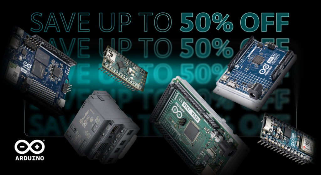
And with the holiday season bringing discounts of up to 50% on selected Arduino® boards, there’s an added incentive to explore what the original Arduino has to offer.

The original Arduino advantage is more than the hardware

An Arduino board may be small enough to fit in your hand, but what comes with it extends far beyond the hardware.  Choosing a genuine Arduino means having access to an ecosystem built to help you turn ideas into working projects. Official documentation, ready-to-use libraries, tutorials, projects, demos, and development tools take much of the guesswork out of the process — whether you’re writing your first lines of code or tackling a sophisticated prototype.

And let’s not forget about the community. Millions of makers, educators, and developers around the world share their knowledge, troubleshoot challenges, and inspire one another through projects that push the boundaries of innovation.

That’s the advantage of the original Arduino. You’re not just purchasing a board. You’re tapping into years of engineering expertise, trusted resources, and a global community that helps you make the best of it.

A board for every ambition — a few favorites to explore

How you bring your projects to life often depends on the tools you choose. Whether you’re experimenting with electronics, connecting devices, or developing a sophisticated prototype, Arduino has a board to match your ambitions. Here are six solid options for the makers, developers, and builders in your life.

Start building. Keep exploring

There’s a reason the Arduino® UNO Rev3 board continues to be a favorite among makers and educators. Its reliability, approachable design, and extensive learning resources make it an excellent tool for exploring electronics, coding, and interactive projects. 

Ready for more processing power? The UNO R4 Minima brings 32-bit performance to the familiar UNO form factor, opening up new opportunities for experimentation.

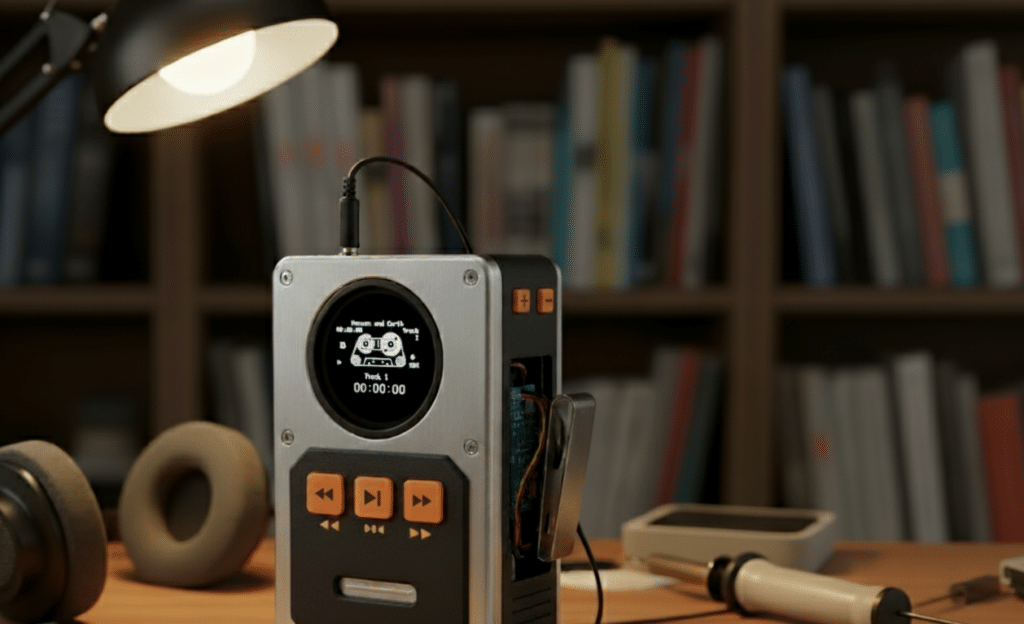
Build your own retro-style MP3 player with the UNO R4 Minima, perfect for music lovers and makers.

Give your projects a smarter edge

Want to make your projects smarter and more connected? The UNO R4 WiFi combines 32-bit processing with WiFi and Bluetooth® wireless connectivity, along with a 12×8 LED matrix, making it a compelling choice for connected devices, automation, and interactive builds. 

For projects where space matters, the compact Arduino® Nano ESP32 board delivers wireless connectivity and support for MicroPython, giving developers plenty of flexibility for IoT applications.

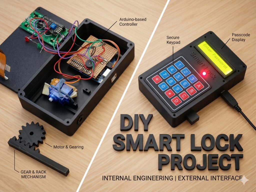
Build a keypad password lock system with the UNO R4 WiFi, which replaces the physical key with a secure digital interface.

Think bigger. Build bolder

Some ideas demand more room to grow. With a generous selection of input/output pins, the Arduino® Mega 2560 board is well suited for projects involving multiple sensors, motors and other components. 

And for developers tackling more computationally demanding applications, the Arduino® GIGA R1 WiFi board brings dual-core processing, wireless connectivity, and advanced peripherals to the workbench.

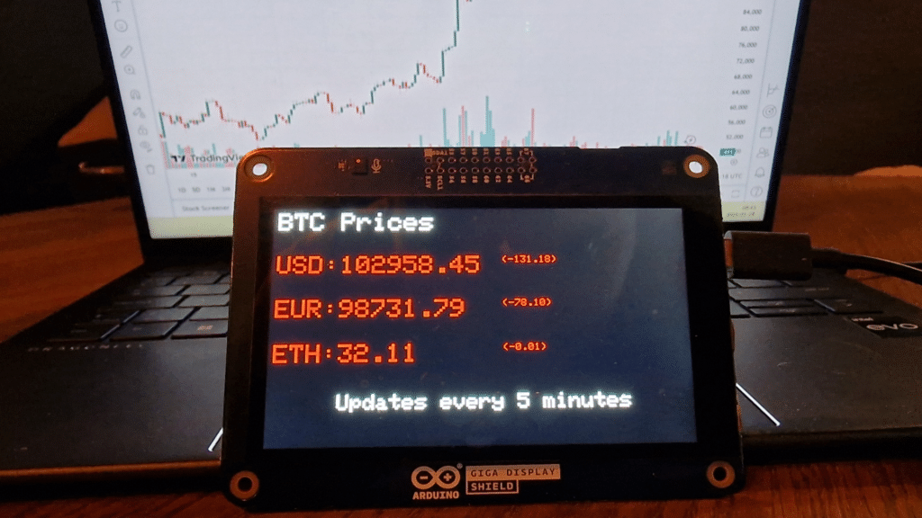
Keep an eye on the ever changing cryptocurrency value on this cryptocurrency tracker with the GIGA R1 and GIGA Display Shield.

Six boards. Different strengths, and one shared purpose: give makers and developers the freedom to experiment, solve problems, and bring ambitious ideas to life.

Big ideas deserve great hardware. And a great deal!

Whether it’s your first experiment or you’re building more sophisticated prototypes, Arduino hardware opens the gates to all kinds of creative and innovative possibilities. And this holiday season, there’s an added reason to explore them. 

If you’ve been waiting to get started with Arduino, expand your collection, or tackle a project that’s been in the planning stages for a while, we’ve got the perfect incentive for you; selected hardware available at discounts up to 50% during our holiday promotion. So what will you build next?

Explore the holiday deals.

Arduino, UNO, Nano, Mega, and GIGA are trademarks or registered trademarks of Arduino S.r.l.

The post What will you build next? Arduino Black Friday deals are here appeared first on Arduino Blog.

Stuff Made Here Built an Arduino-Run Car Wash for His Muddy Dog, and the Dog Said No

Stuff Made Here Built an Arduino-Run Car Wash for His Muddy Dog, and the Dog Said No

Shane Wighton of Stuff Made Here built an Arduino-controlled car-wash-style rig for his muddy dog. The viral video shows the machine in action, tackling the problem of mud splashes, though the dog…

Aswinth Raj
Circuit Digest 03 Nov 00:04

This 3D-Printed Robot Duck Learned to Walk With a Neural Network, and Now It Kicks a Ball

This 3D-Printed Robot Duck Learned to Walk With a Neural Network, and Now It Kicks a Ball

XGO-Duck, an open-source 3D-printed robot duck, uses a neural network on an Arduino UNO Q to learn to walk. Developed by Luwu Dynamics, it recently demonstrated kicking a ball, becoming a top post on…

Aswinth Raj
Circuit Digest 02 Nov 00:07

A $300 Robot That Plays Fetch: It Finds the Ball, Picks It Up and Brings It Back on Its Own

A $300 Robot That Plays Fetch: It Finds the Ball, Picks It Up and Brings It Back on Its Own

A hobbyist built a $300 3D-printed robot named Fetch that autonomously finds an orange ball, picks it up, and brings it back to its owner, using an Arduino UNO Q and a custom Edge Impulse vision…

Aswinth Raj
Circuit Digest 02 Nov 00:06

XGO Duck: the open source robot duck that walks with neural policies

XGO Duck is an open source, 3D-printable robot duck that Luwu Dynamics built starting from Pollen Robotics’ Microduck. From the original project it keeps the body, the layout of the 15 servos and the joint order, but replaces all of the electronics. In place of the Pollen Robotics board there is an Arduino UNO Q, which runs neural policies for walking, getting up from the ground and picking. So there is no need to wait for a commercial robot: anyone with a 3D printer can build one.

The heart of the system is the Arduino UNO Q itself, which hosts two computers on a single board. On one side there is a host with a Qualcomm processor running Linux, on the other an STM32U585 MCU running Zephyr. This division of tasks is the most interesting architectural choice in the project. The host handles the neural policies, the MCU handles real-time motor control. On top of that, the link between the two is a 2 Mbps Bridge, so the two worlds stay synchronised without Linux ever having to wait on the servo bus.

Two computers, two loops: 50 Hz for the policies and 100 Hz for the bus

The host runs the ONNX policies at 50 Hz on a dedicated thread, with the web UI listening on port 9527. The MCU, on the other hand, runs a 100 Hz bus loop and does not wait for Linux. It publishes a 240-byte duck_state snapshot at 100 Hz; the host filters every snapshot on arrival and the 50 Hz thread reads the latest available one, skipping late cycles. That way the robot does not stall if the host is busy.

The servo bus always addresses all 15 servos in the order ID 10-14, 20-24, 30-34. The order in action 14-D of the policy is instead 10-14, 30-33, 20-24. The servo bus is on Serial1 at 1 Mbps, while the QMI8658 IMU is on Wire at 400 kHz, with I2C address 0x6A then 0x6B. Servo positions are saturated to the encoder range 0-4095, with a raw centre position of 2047.

  • 15 FeeTech 1910 servos on a serial bus
  • Arduino UNO Q with Qualcomm host and STM32U585 MCU
  • QMI8658 IMU on the Wire bus at 400 kHz
  • Bridge host-MCU link at 2 Mbps
  • servo bus on Serial1 at 1 Mbps

The neural policies: observation [1, 61], action [1, 14] and automatic get-up

The policies expect an observation [1, 61] and output an action [1, 14]. There are three: xgoduck_walk.onnx for walking, xgoduck_getup.onnx for getting up from the ground and xgoduck_pick.onnx for the pick, which lasts 4 s. A tilt above 55° for 0.15 s triggers the get-up model, then the action is forced to 0 for 1 s. When the tilt drops below 15° for 1 s, the robot goes back to walking.

The home pose has hip and ankle at ±24°, knee at 0°, hip roll at ±5°, neck and head pitch at 20°, mouth at 0°. The action_scale is 1. The walking commands are vx ±0.4, vy ±0.3 and ωz ±1.0, with a joystick dead zone of 0.1. The four head channels sit within ±1 radian. The mouth is driven from the web UI from 0° to 30°, and in the pick cycle it opens to 30° and closes when φ ≥ 0.4.

Action smoothing uses α = 0.45 on the slices [0:5], [5:10] and [10:14], yaw smoothing uses α = 0.5 and joint speed smoothing uses α = 0.4. The gravity complementary filter uses τ = 0.3 s, with accelerometer correction dropping when the norm deviates from 1 g by more than about 20%. Position control stops if commands are missing for 250 ms or if the IMU is missing for 100 ms; a host feedback older than 150 ms disarms it.

The Zephyr firmware, servo calibration and the web UI on port 9527

The firmware is a CLI app built with Arduino Zephyr core 1.0.0, on top of RouterBridge 0.4.3, RPClite 0.3.1 and MsgPack 0.4.2. A patch to RouterBridge 0.4.3 raises the RPC thread stack from 500 to 4096 bytes, and the serial router is set to 2 Mbps. Calibration and servo setup use a 2 s heartbeat. The temporary gains for the centring movement are KP = 6 and KD = 20, with a temporary KP = 10 for the servo with ID 34. During calibration the gains become KP = 3 and KD = 0, and every servo is commanded to 2047.

The servo setup page starts with default values KP = 5 and KD = 20. Writing the ID unlocks register 0x37 and then writes 0x05; writing KP/KD unlocks 0x37 and stores both bytes at 0x15. The duck_command sent by the host is 80 bytes. Closing the page or leaving it in the background for more than 1 s disables position control, so the web UI is not just a convenience panel.

The Luwu Dynamics repository collects the project code: sketch, configurations, ONNX models and support scripts. Among the tools are tools/prepare-bridge.py, tools/router-2m.sh, tools/reuse-toolchain.py, tools/verify-elf.py and tools/measure.py, which measures for 60 seconds. There are also python/rl_core.py, python/requirements.txt, sketch/sketch.yaml, app.yaml, data/zero_pos.json and sketch/duck_config.h. Anyone who wants to rebuild it will find everything needed to get started there.

The host needs a Linux environment with ONNX Runtime and Python, while the MCU runs on Zephyr. The UNO Q loader error in case of a tail-call is ENOEXEC (−8), a detail familiar to anyone who compiles firmware. The default rate of Bridge.begin() in another app is 115200, so it has to be raised to 2 Mbps to run the bus as needed. If you want to start with the right hardware, an Arduino UNO Q with a complete accessory kit covers the host and MCU side on a single board.

Source: https://github.com/LuwuDynamics/xgoduck_runtime_arduino

Related products

The post XGO Duck: the open source robot duck that walks with neural policies appeared first on Open Electronics.
Arduino examples for the 6-colour e-paper display on the reTerminal E1002

Driving a 6-colour e-paper display is not like driving a monochrome panel. Seeed Studio’s reTerminal E1002 carries a 7.3-inch ACeP with 800×480 resolution, and a XIAO ESP32-S3 runs underneath it. Mariusz Jurgielewicz has put together a set of Arduino examples tested on exactly this combination, so newcomers don’t have to reinvent pinout, polarity and refresh sequences.

The practical value of the collection lies in the details the official drivers don’t tell you. The GDEP073E01 panel uses the ED2208 controller and is wired to the carrier through an internal FPC. So the pins are not the ones you’d expect from a breakout module: SCK is on GPIO 7, MOSI on GPIO 9, CS on GPIO 10, DC on GPIO 11, RST on GPIO 12 and BUSY on GPIO 13. Logging is also duplicated across two serials, Serial1 on GPIO 43 and GPIO 44 through the USB-UART bridge, plus the XIAO ESP32-S3’s native USB CDC Serial.

BUSY active-low and SPI clock at 2 MHz

Trap number one is the BUSY polarity. On the ED2208 the signal is active-low: 0 means refresh in progress, 1 means ready. Inverting it locks up the driver or corrupts subsequent writes, and the symptom isn’t a clear error but a panel that stays half-drawn.

The second trap is the clock. The SPI bus runs reliably at 2 MHz, and this also applies to the upload speed set in the Arduino IDE, fixed at 115200. The log serial runs at 115200 baud. Higher frequencies on the internal flex risk clock distortion, with pixel dropouts or corrupted command bytes. Finally there’s the watchdog: during a cold refresh the 40-second timeout can fire, so the sequence has to be handled accordingly.

  • SCK on GPIO 7, MOSI on GPIO 9, CS on GPIO 10
  • DC on GPIO 11, RST on GPIO 12, BUSY on GPIO 13
  • BUSY active-low: 0 refresh in progress, 1 ready
  • Reliable SPI clock at 2 MHz
  • Serial1 on GPIO 43 (TX) and GPIO 44 (RX), plus native USB CDC
  • 192,000 bytes of frame buffer in OPI PSRAM

A full frame buffer of 800×480 pixels at 4 bits per pixel, two pixels per byte, requires 192,000 bytes. It doesn’t fit in the ESP32-S3’s internal RAM, so it has to be buffered in OPI PSRAM. The panel exposes 6 native solid colour fields: black, white, red, green, blue and yellow. So each pixel is not a grey value but a colour index, and dithering has to be planned accordingly.

On the software side the collection covers three driver stacks. The first is Jean-Marc Zingg’s GxEPD2, the upstream one you get from the Library Manager. The second is the Good Display vendor driver. The third is Waveshare’s GUI_Paint graphics framework, sitting on top of Adafruit_GFX. Watch out for one detail: the Seeed_GxEPD2 fork should not be installed, because it conflicts with the upstream GxEPD2.

Besides the display, the examples cover the carrier board’s onboard peripherals. There’s the PCF8563 real time clock and the SHT4x environmental sensor, so a complete project can show the time plus temperature and humidity data without adding external modules. Anyone who wants to rebuild everything from scratch will find Mariusz Jurgielewicz’s repository with the sketches ready to upload.

To work on it you need the Arduino IDE with XIAO ESP32-S3 support, the GxEPD2 library from the Library Manager, and the panel connected to the carrier.

Source: https://github.com/melastmohican/reTerminal-E1002-arduino-examples

The post Arduino examples for the 6-colour e-paper display on the reTerminal E1002 appeared first on Open Electronics.
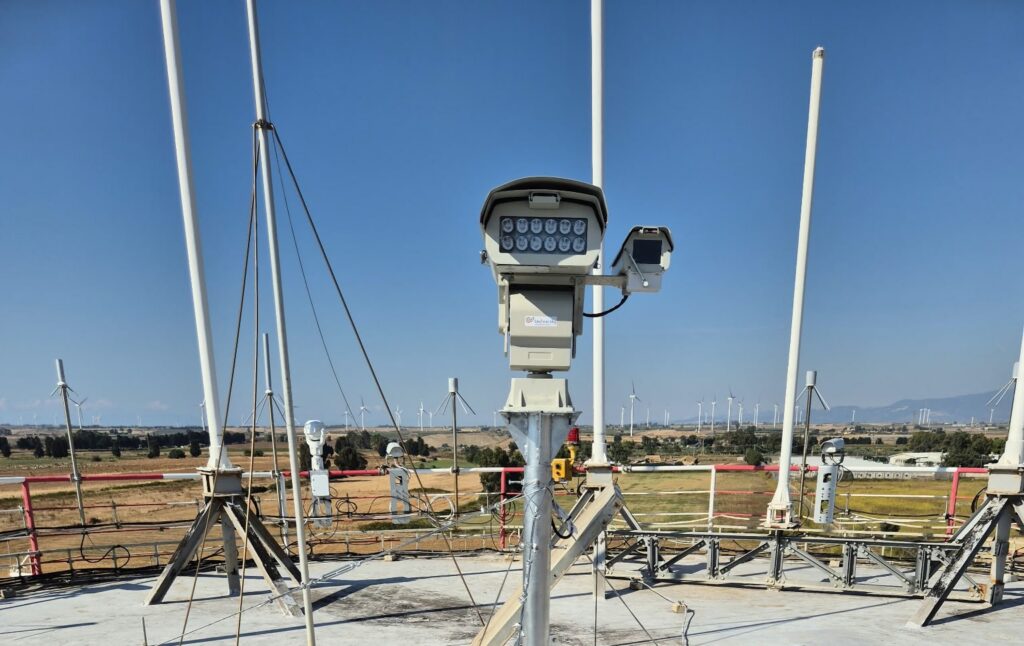
How Techno Sky and Arduino Opta brought an industrial visual emergency signaling solution to air traffic management

When you’re developing systems that support air navigation services, the margin for compromise is essentially zero. Reliability isn’t a “nice to have,” it’s the baseline. That’s the world in which Techno Sky operates, and it’s what makes their decision to build around the Arduino® Opta RS485 microPLC responsive to the project’s identified requirements.

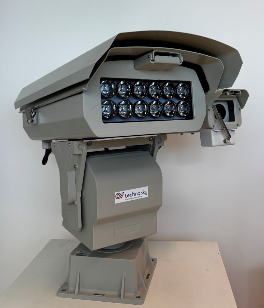
Techno Sky is an ENAV Group company that manages and maintains hardware and software systems supporting air navigation services, and develops innovative technologies for the Air Traffic Management (ATM) sector. Their R&D department works on solutions for air navigation service providers (ANSPs), airports, aviation authorities, and organizations worldwide – systems designed for use under demanding operational conditions.

The challenge: a compact, reliable visual emergency signaling system

The project that brought Techno Sky to Arduino was the development of a visual emergency signaling system for integration within ENAV’s Digital Tower environment. The requirements were unambiguous: industrial-grade reliability, compact form factor, continuous operating capability, Ethernet and industrial communication interfaces, integrated I/O, and the ability to develop and maintain the system without building dedicated custom electronics from scratch.

A fully custom hardware design was on the table, but it would have added significant time and complexity – hardware design, integration, and validation cycles that would delay the project without necessarily improving the outcome. The team needed a platform that would let them focus on application logic and system integration, not on reinventing the controller underneath it.

Opta: a non-conventional, but versatile and effective path to innovation

The R&D team evaluated conventional PLCs, custom embedded electronics, and single-board computers before landing on Opta. It selected Opta based on its combination of industrial characteristics and software flexibility in a single package. The team determined that the conventional PLCs it evaluated offered less development agility for this project. Custom electronics would have added hardware design overhead. The single-board computers evaluated by the team did not meet the project’s identified specifications.

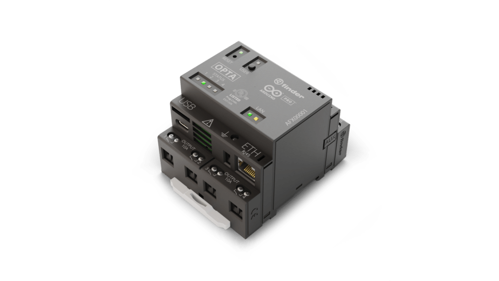
The Opta RS485 offered integrated Ethernet and RS485 communications, relay outputs, and the flexibility of the Arduino programming environment and library ecosystem – all in a compact, DIN rail-mountable form factor designed for industrial applications. Critically, it allowed new functionality to be implemented through software without adding dedicated hardware, a quality that would prove important as the system evolved.

An architecture for in-house deployment within the year

In the deployed system, Opta acts as the main embedded controller, managing signaling outputs, Ethernet communication, RS485 communication with external equipment, operating modes and timing, supervision functions, and communication integrity and security. The system currently implements eight signaling modes on a single controller – functions that the Techno Sky team determined could otherwise have required additional hardware or a more complex architecture.

The main engineering challenge during development was coordinating communications, physical outputs, signaling sequences, and supervision in parallel. The team addressed this through a modular software architecture and the use of watchdog and communication-validation mechanisms – approaches intended to support a manageable codebase and consistent system behavior. Development was carried out internally by Techno Sky’s R&D team using Arduino documentation, libraries, and development resources.

According to Techno Sky, the project started in October and reached operational deployment in under 12 months. One Opta controller integrating more than ten main control functions, designed for continuous operation, with the same architecture carried through from R&D prototype to operational system.

From prototype to production on the same platform

That last point deserves emphasis. R&D teams may prototype on one platform and later transition hardware when moving toward deployment. Techno Sky didn’t need to make that transition. The architecture based on Opta developed during R&D was the architecture retained for operational use – a decision that they report was based on its assessment of the platform for this application.

Techno Sky summarized their experience: “Opta enabled us to move rapidly from an R&D concept to an operational solution. Its industrial hardware, combined with the Arduino programming environment and library ecosystem, allowed us to integrate and expand multiple functions without increasing hardware complexity. The fact that we are retaining Opta in the operational system reflects our positive assessment of its effectiveness and reliability for this application.”

More ideas, more innovation

The Techno Sky team has been working with Arduino platforms across their R&D activities for several years, and this project showcases their reinforced confidence in their chosen Arduino product line. Future applications under consideration include monitoring systems, remote control, sensor integration, robotics, automated test equipment, and ATM infrastructure – a range of potential uses that Techno Sky is evaluating.

For teams facing similar integration challenges – multiple control and communication functions, demanding reliability requirements, and pressure to move quickly from concept to deployment – Techno Sky’s assessment is direct: Opta is well suited, in Techno Sky’s assessment, when those functions need to come together in a compact system, without the overhead of custom hardware design.

Ready to explore options for your industrial application? Find out more about the Opta family and Arduino’s industrial-grade range at arduino.cc/pro.

Arduino, Opta, and the Arduino logo are trademarks or registered trademarks of Arduino S.r.l.

The post How Techno Sky and Arduino Opta brought an industrial visual emergency signaling solution to air traffic management appeared first on Arduino Blog.

How about a Hallowuino half-dozen?

It’s almost that time of year again! No chance to 3D print your Arduino®-powered pumpkin project? Didn’t get around to animating the LEDs on your costume? There’s still time, and here’s a half-dozen Hallowuino-themed projects to get you inspired.

Spooky, Sassy Pumpkin

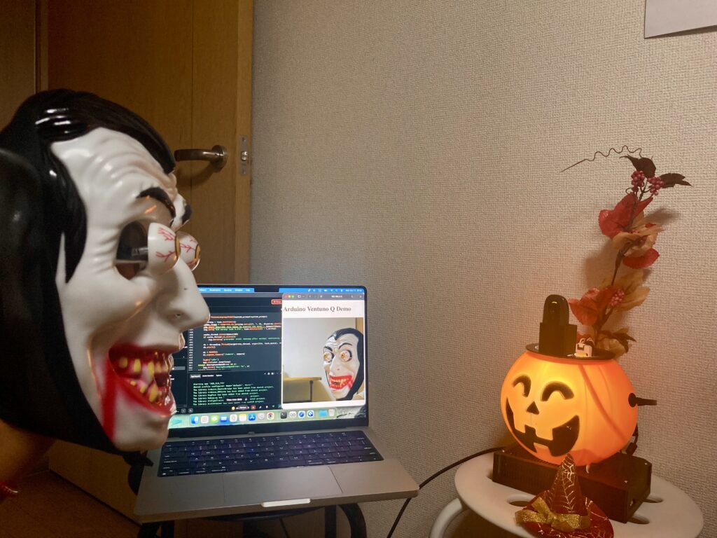
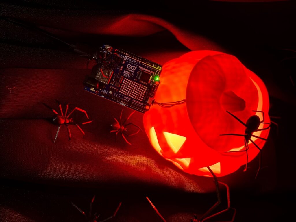
You’ve heard of Spooky, Scary Skeletons, well here’s a Spooky, Sassy Pumpkin that is built to use a USB webcam to identify visitors as they approach, then answer their questions about what it sees using the Arduino App Lab Vision-Language Model (VLM) Brick. This jack-o’-lantern packs a whole lot more smarts than your average fruit thanks to the dual-brain VENTUNO Q concealed underneath it. All processing is designed to be handled offline, on-device without sending users’ faces and voices  across networks or to the cloud.

Arduino-Powered Animatronic Supergroup

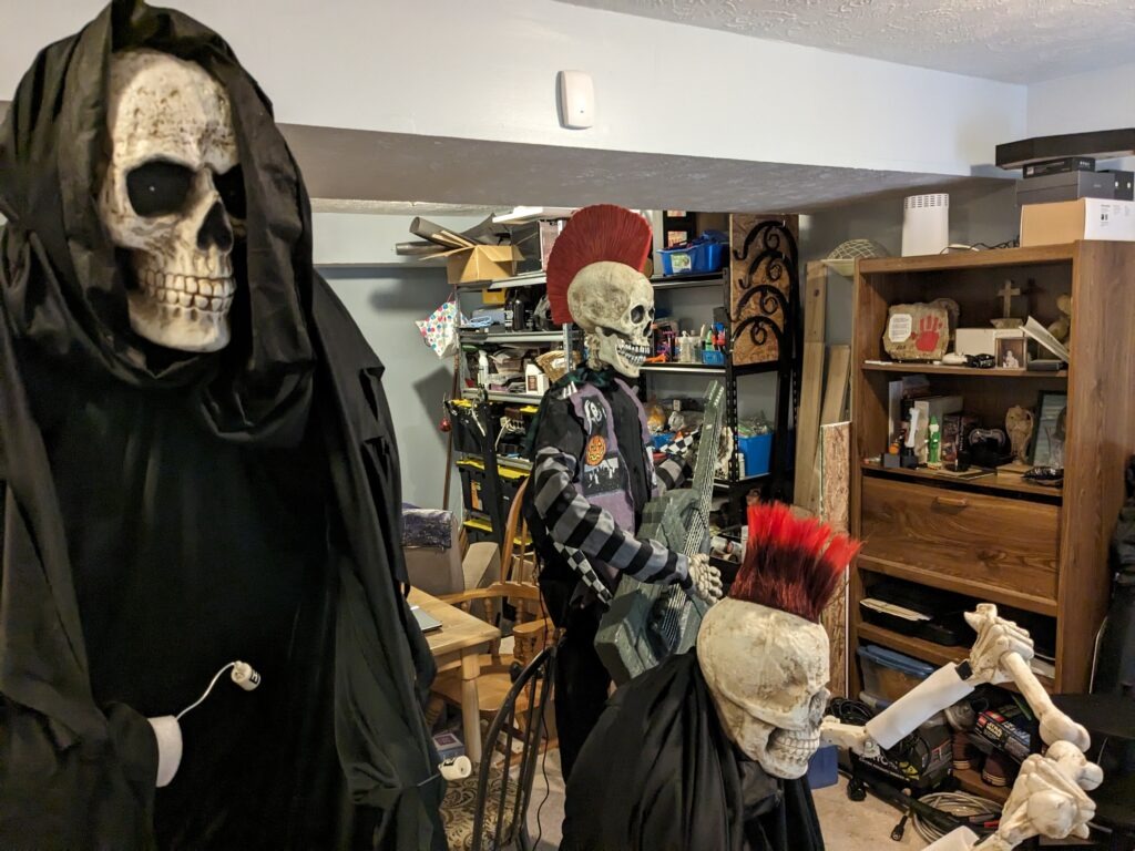
Bands break up for all kinds of reasons, so we were pleased to see Arduino Project Hub member nerdabilly figure out a way to sync the Costco Skeleton Punk Rocker animatronic with the Lowe’s Reaper Band. The band members are centered around a Bluetooth speaker, while the rocker is triggered by a timer or motion sensor. Not wanting to permanently alter these expensive displays, nerdabilly used the existing analog signal from the band leader to trigger the pink in place of its motion-sensing trigger, so the whole crew can rock out with their skulls out. Nerdabilly, we salute you for keeping this spooky symphony in sync!

Simple Spookiness with Modulinos and MP3s

Here’s some simple steps to sprinkle some spookiness into your season from our own team. Using the UNO R4-based Plug and Make Kit, plus a DFRobot DFPlayer MP3 player module, we show you how to trigger spooky lights and sounds when the Modulino® Distance sensor detects a presence. You can even connect to the Arduino Cloud to activate, customize, and monitor your project remotely. And that’s just the start – the seven included modules and built-in Wi-Fi give you plenty of options for creating your own frightful projects!

Ultrasonic Spider

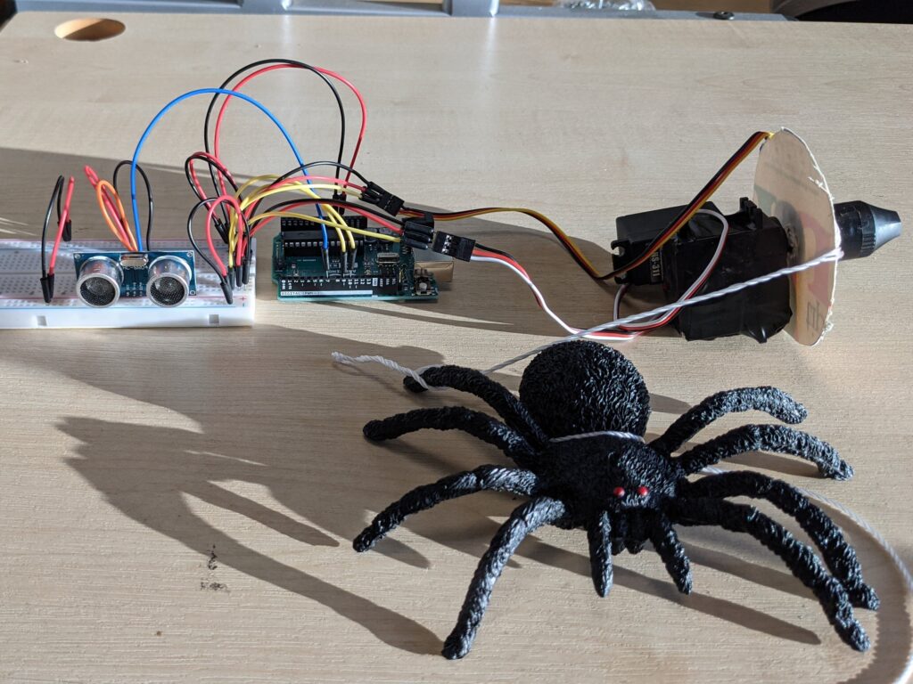
Everyone has to start their Arduino journey somewhere, and for Project Hub member ParzivalUK, that place was a half-decade old project video demonstrating a fake spider dropping on unsuspecting passers-by. Unfortunately, ParzivalUK found that the accompanying code no longer worked for their project, and there weren’t detailed steps on how to recreate it. Driven by a desire to delight their son with a fun Halloween prank, ParzivalUK pushed on, combining a servo with an ultrasonic sensor to drop a toy spider on anyone who comes within approximately 40cm of the trap, with a continuous rotation servo to wind it back up, ready for the next victim!

Portal Sentry Turret

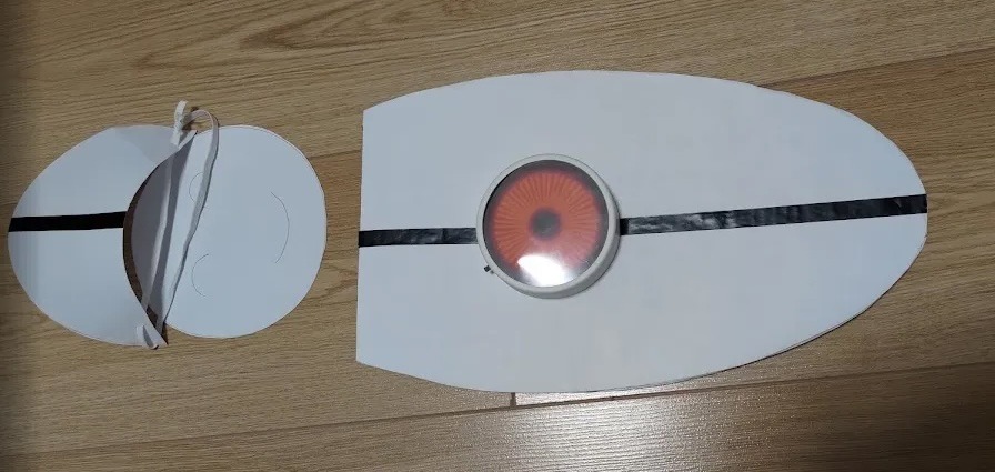
We love seeing projects shared on the unofficial Arduino Discord server. User jaysicks’ Aperture Science Sentry Turret costume really caught our eye, and we asked for a little more detail. The resulting Instructable is a detailed step-by-step guide for recreating the iconic tripod robot from one of the most beloved puzzle platformers of all time. With no 3D printer at hand, the costume relies on cardboard construction but comes out looking great. A red LED in the eye responds to the audio output from the incorporated GD380D-M audio playback module when a button is pressed, and the whole thing is controlled by an ATtiny85V microcontroller, programmed using the Arduino IDE. We think jaysicks’ son will be the envy of the neighborhood this Halloween, or at least among those with a solid appreciation of classic video games!

Cyber Research Systems T-1-7 Warrior Robot

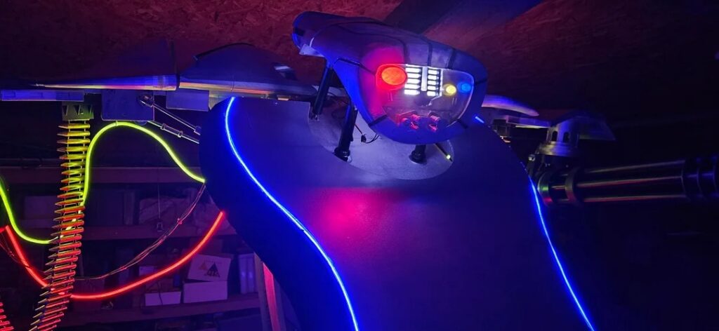
The T-800 and T-1000 may get most of the screen time, but Redditor u/parsupo recreated the more niche T-1-7 Warrior Robot for their annual Halloween project. Built around an electric wheelchair base, the bot uses an Arduino Mega 2560 to receive and process commands from a remote control, and the same ATmega328 chips found in the UNO to control lights, gun movement, and the head. It may not be made of mimetic polyalloy, but we wouldn’t want to run into it in a dark alley!

What will you make?

Got a spooky Arduino-based project to share? Or need help realizing your creation? Head over to the Arduino subreddit and let us know!

The post How about a Hallowuino half-dozen? appeared first on Arduino Blog.