Posts with «open hardware» label

MAX7219 LED Matrix with Arduino: Wiring and Library Guide

Let’s find out how to use the MAX7219 to drive an LED matrix. Wiring, Arduino libraries and sketches will guide us through building custom graphic and numeric displays.

An LED matrix display is one of the most fascinating components for anyone starting to experiment with Arduino: with a small square module we can bring to life numbers, letters, symbols and animations that immediately catch the eye. The problem? An 8×8 matrix means no fewer than 64 LEDs to control individually: an almost impossible task without dedicated support. That is where the MAX7219 chip comes in, an IC designed specifically to simplify the management of matrix and 7-segment displays, reducing the connection to the Arduino board to just a few pins. In this article we will see how to connect the MAX7219 to an 8×8 matrix, how to use the ready-made modules available on the market and how to program everything with the LedControl library.

The MAX7219

Fig. 1 Pinout of the chip and of the display.

The MAX7219 chip has 24 pins. The 8×8 display (Fig. 1) is connected so that the rows are linked to the DIG pins and the columns to the SEG pins of the MAX7219.

Brightness is varied in software after setting the maximum current with an external resistor connected to the Iset pin. Three pins are dedicated to communication with the control board: DIN (to transfer data from the board to the chip), CS (for device selection) and CLK (for the data clock). A further pin, DOUT, is used to connect the DIN of the next chip, in case you want to chain several LED matrices together (for example to build scrolling text).

The complete schematic of the connection between the chip and the display is shown in Fig. 2, with particular emphasis on the links to the Arduino board and to a second chip. Using the MAX7219 is made even simpler by the availability on the market of modules (such as those in Fig. 3) that integrate both the chip and the LED matrix, along with the relevant wiring.

Fig. 2 Schematic of the connection between the chip and the display.
Fig. 3 Schematic of the connection between modules and the Arduino board.

Using a module reduces the wiring to just the connections between the module and the Arduino board, and between modules possibly arranged in a chain. Each module has 5 input pins (VCC, GND, DIN, CS/LOAD and CLK, to be connected to a board such as the Arduino UNO R3) and 5 output pins (VCC, GND, DOUT, CS and CLK, for any subsequent modules in the chain). The Arduino UNO R3 board can be replaced by the more recent Arduino UNO R4 versions, available in the Minima and WIFI models, both fully compatible electrically and in software with the previous R3. Both versions keep the same pin layout and are compatible with most shields and libraries already developed for the R3.

Programming with Arduino

Several libraries make programming the MAX7219 easier; among them, in particular, the LedControl library, which is very widespread and simple to use.

The basic commands are as follows:

#include “LedControl.h” LedControl LC=LedControl (DIN, CLK, CS, number_of_modules)

An object of the LedControl class is created, to which an identifying name is assigned (for example, LC). The DIN, CLK and CS parameters will be replaced with the numbers of the Arduino pins (for example: 2, 4, 3) to which the respective signals are connected.

LC.SHUT (module_number, 0/1)

Enables or disables the chip. The value 0 makes it operational, while 1 puts it in standby. On power-up, the chip is in standby mode by default. The module_number parameter identifies the module in a serial chain, numbered starting from 0.

lc.setIntensity (module_number, intensity)

Adjusts the brightness of the LEDs, with a value between 0 (minimum) and 15 (maximum). The value 0 does not turn the LEDs completely off; to do that, you need to use LC.Shutdown(module_number, 1).

lc.clearDisplay (module_number)

Turns off all the LEDs of the specified module, clearing the displayed content.

lc.setLed (module_number, row_number, column_number, state)

Turns a single LED on or off. row_number and column_number indicate the position of the LED (numbered from 0 to 7). state = true (or 1) turns the LED on, false (or 0) turns it off. Rows are numbered from 0 (top) to 7 (bottom), columns from 0 (left) to 7 (right). For example, the top-left LED occupies position (0, 0), the bottom-right one (7, 7).

lc.setRow (module_number, row_number, byte)

Lets you turn all the LEDs of a row on or off, specifying their state with a binary byte. For example, to turn on the first four LEDs of a row you use: B11110000.

lc.setColumn (module_number, column_number, byte)

Works in a similar way to setRow, but acts on a column. The byte defines which LEDs to turn on or off in the specified column. Let’s now look at some practical examples of use.

Example 1

The first sketch, shown in Listing 1, is meant to display the 8 rows in sequence, one at a time, starting from the top; then the 8 columns, one at a time, starting from the left; then the 8 rows starting from the bottom; then the 8 columns starting from the right. Finally, all the LEDs are turned on gradually in pairs of rows, starting from the two middle rows and following the order: 4-5, 3-6, 2-7, 1-8. In this last phase, the lighting happens at low intensity, with brightness varying progressively from 10 to 2.

The first sketch lights up rows and columns of the matrix in sequence.

Example 2

The purpose of this sketch (Listing 2) is to gradually light up the LEDs of the matrix rows starting from the bottom, as a consequence of a voltage varying between 0 V and 5 V set by a potentiometer connected to pin A5; the comments inside the sketch describe how the gradual lighting works.

The second sketch lights the rows gradually as the potentiometer voltage changes.

Using arrays

The goals of the two previous examples can be achieved in a similar way using arrays. One approach is to define the row structure inside an array of bytes (for example in binary): with 8 elements of 8 bits you describe the LED states of the whole display. The first cell of the array corresponds to the state of the eight LEDs of row 0 (from left to right), the second to that of row 1, and so on up to row 7.

If, for example, you want to turn off all the LEDs of the first four rows and turn on those of the last four, you can use the following array:

byte array [8]={B00000000,B00000000,B00000000,B00000000,B11111111,B11111111,B11111111,B11111111};

To display it on the screen you can proceed using the following code:

for (row=0; row<8; row++) {lc.setRow(0,row,array[row]);}delay (3000);

An editor that lets you obtain the binary codes of the most commonly used symbols more quickly is available at the following link: https://xantorohara.github.io/led-matrix-editor

Example 3

The purpose of this sketch (Listing 3) is to display in sequence all the numbers between 0 and 9 using 10 arrays that define the numbers and 10 for loops that call them up.

The third sketch displays the digits 0 to 9 in sequence.

Example 4

The fourth sketch shows temperature and humidity thresholds on the matrix.
Fig. 4 Display of the temperature and humidity thresholds.

The purpose of this sketch (Listing 4) is to show when certain temperature and humidity thresholds (set in the program) are exceeded, as shown in Fig. 4. In the left half of the display (columns 0-1-2) the temperature data is shown, while in the right half (columns 5-6-7) the humidity data is shown. In the upper part of the display (rows 0-1-2) the letters T and U appear; in the lower part (rows 4-5-6-7) the lighting of the LEDs indicates that a given temperature or humidity threshold has been reached.

Four thresholds are defined in the code: as the value increases, the corresponding rows light up progressively, starting from row 7. Temperature and humidity are measured with the HTS221 sensor, integrated into the STMicroelectronics IKS01A3 expansion board (Fig. 5), mounted on the Arduino UNO board. Those who do not have this board can use other sensors, such as the DHT11 or DHT22, adapting the data acquisition part of the software accordingly.

Fig. 5 The IKS01A3 expansion board.

Conclusion

The MAX7219 makes LED matrix management accessible to everyone, turning a complex task into a fun, stimulating and creative experience. Once you understand the basic commands, the possibilities become practically endless: custom scrolling text, small animations, graphic indicators, simple light games and real-time data visualisations. All that is left is to experiment, adapt the sketches provided and let yourself be inspired: with a simple LED matrix your Arduino project can finally “speak with light” in a clear, dynamic and original way.

Related products

The post MAX7219 LED Matrix with Arduino: Wiring and Library Guide appeared first on Open Electronics.

Arduino UNO Q 4GB: A Dual-Brain Board for Physical AI

Physical AI needs a board that can think and act at the same time. This project pairs a Qualcomm Dragonwing IQ8 processor with an STM32H5 in a dual-brain architecture. The first runs AI models with 40 TOPS, while the second controls motors and peripherals in real time. The result is a complete platform for robotics and automation.

The board carries 16 GB of LPDDR5 RAM and 64 GB of eMMC storage. Connectivity includes tri-band Wi-Fi 6, Bluetooth 5.3, 2.5 Gb Ethernet, and CAN-FD. The board with integrated display from the Arduino UNO Q family offers a similar starting point for anyone approaching this world. The project board is open source and free of proprietary lock-ins.

How the dual-brain architecture works

The Qualcomm Dragonwing IQ8 processor handles the artificial intelligence. The STM32H5, on the other hand, guarantees deterministic control over motors, CAN bus, and other peripherals. The two processors communicate efficiently, so the AI can make decisions and the hardware executes without unpredictable latencies.

The preinstalled operating system is Ubuntu with an Ubuntu Pro license. The Arduino core runs on Zephyr RTOS, which offers guaranteed response times. In addition, the environment supports VS Code, PyCharm, Jupyter, and Docker for development.

AI models optimized for the NPU run through Arduino App Lab. The platform supports importing GGUF models from Hugging Face and training with Edge Impulse Studio. There are over 100 ready-to-use examples.

  • 40 TOPS of AI power
  • 16 GB LPDDR5 RAM
  • 64 GB eMMC
  • Tri-band Wi-Fi 6 (2.4/5/6 GHz)
  • Bluetooth 5.3
  • 2.5 Gb Ethernet
  • CAN-FD

Why a board for Physical AI is needed

Modern robotics requires perception, decision, and action in a single device. This board unifies everything in an open format. Makers can prototype with Arduino UNO shields and Raspberry Pi HATs. Moreover, ROS 2 support and the CAN-FD, I2C/I3C, SPI, PWM, and UART interfaces make it suitable for professional projects.

Compatibility with existing shields lets you reuse sensors and actuators you already own. For example, those with the more powerful processor board from the Raspberry Pi family can compare performance. In addition, the Works with Arduino program allows scaling prototypes to production level with certified SOMs from SECO and Toradex.

An open ecosystem for physical AI

The board uses Ubuntu Pro as its main operating system. Zephyr RTOS handles real-time hardware control. This mix ensures flexibility for development and robustness for execution.

Arduino App Lab is the access point for AI models. It supports importing from Hugging Face and training with Edge Impulse. There are also over 100 ready-made examples to get started right away.

The board is powered by a 65W USB-C power supply. It is designed for those who want to move from prototyping to production without changing platforms. Finally, support for Arduino shields and Raspberry Pi HATs makes it versatile.

For those starting out with embedded AI, the board with the STM32 microcontroller offers a simpler alternative. However, this board represents the next step for advanced robotics projects. Physical AI thus becomes accessible to makers, educators, and professionals.

Source: https://www.qualcomm.com/internet-of-things/products/iq8-series

The post Arduino UNO Q 4GB: A Dual-Brain Board for Physical AI appeared first on Open Electronics.

Upline: a minimal serial protocol for 8-bit IoT

Upline is a minimal serial protocol that turns any microcontroller into an IoT device. The project sheet describes a system based on newline-delimited ASCII records, with a complete Arduino implementation in a single header. The project, by smlcrft, targets 8-bit chips with very limited resources.

The operation is simple. The byte stream is split into lines using LF or CR terminators, ignoring empty lines and those that do not start with the ‘^’ character. Each line is a list of independent entries, delimited by the same ‘^’ character. Each entry represents an operation on a specific key.

How the Upline protocol works

Entries are only processed if fully delimited by two carets. This way partial data is never applied, and an interrupted communication does not leave the device in an inconsistent state. Writes are confirmed via an echo of the value actually in use: this distinguishes a rejection from a loss of communication.

A periodic heartbeat demonstrates that the device is alive and speaks the Upline protocol. This limits the receiver’s wait time, which immediately knows if the node is operational. The protocol also supports escaping special characters with six symbolic sequences, and does not require floating-point numbers: it uses the fixN format for decimals.

  • 4,060 bytes of flash on ATmega328P, 358 bytes of SRAM
  • 3,168 bytes of flash on ATtiny85, 253 bytes of SRAM
  • 2,100 bytes of flash on ATtiny85 in transmit-only mode
  • 98 bytes for a universal line reader on ATmega328P

The numbers are remarkable for a complete protocol. On ATmega328P, 4,060 bytes of flash and 358 bytes of SRAM are needed. On ATtiny85, consumption drops to 3,168 bytes, and in transmit-only mode to 2,100 bytes. The project sheet also reports 98 bytes for a universal line reader on ATmega328P.

Why Upline matters to makers

Upline lets you turn any microcontroller into an IoT device with a minimal, efficient, and robust protocol. The philosophy is the opposite of heavy frameworks: here everything fits in one header and runs even on 8-bit chips with only a few hundred free bytes. An Arduino Nano ESP32 board can use the same protocol as an ATtiny85, simplifying communication between heterogeneous nodes.

The protocol is particularly suited to those building distributed sensors, remote actuators, or small monitoring nodes. Moreover, the echo confirmation makes the system reliable even over noisy radio links. To connect a node to a PC and read the record stream, just use a 3.3 V / 5 V USB-serial converter: Upline speaks over any UART.

Getting started with Upline

To start, simply download the upline-arduino header and include it in an Arduino project. The fact sheet lists support for ATmega328P, ATtiny85, SAMD21, ESP32, and RP2040, among others. An Uno R3 with an ATmega328 is a great test bench to learn the protocol without soldering anything: those are the 4,060 bytes of flash measured by the author.

The source code is a single header file, so integration is immediate. No external libraries or complex build tools are needed. A USB ATtiny85 board is instead the project’s edge case: 3,168 bytes of flash and 253 of SRAM, and the protocol fits entirely inside.

Finally, the project documentation reports precise numbers for each configuration. This helps choose the right microcontroller based on flash and SRAM budget. For the smallest projects, transmit-only mode on ATtiny85 requires just 112 bytes of SRAM.

Source: https://github.com/smlcrft/upline-serial-protocol

Related products

The post Upline: a minimal serial protocol for 8-bit IoT appeared first on Open Electronics.

Stecchino Game is all about Balancing a Big Toothpick

Stecchino demo by the creator

Self-described “Inventor Dad” [pepelepoisson]’s project is called Stecchino (English translation link here) and it’s an Arduino-based physical balancing game that aims to be intuitive to use and play for all ages. Using the Stecchino (‘toothpick’ in Italian) consists of balancing the device on your hand and trying to keep it upright for as long as possible. The LED strip fills up as time passes, and it keeps records of high scores. It was specifically designed to be instantly understood and simple to use by people of all ages, and we think it has succeeded in this brilliantly.

To sense orientation and movement, Stecchino uses an MPU-6050 gyro and accelerometer board. An RGB LED strip gives feedback, and it includes a small li-po cell and charger board for easy recharging via USB. The enclosure is made from a few layers of laser-cut and laser-engraved material that also holds the components in place. The WS2828B LED strip used is technically a 5 V unit, but [pepelepoisson] found that feeding them direct from the 3.7 V cell works just fine; it’s not until the cell drops to about three volts that things start to glitch out. All source code and design files are on GitHub.

Games are great, and the wonderful options available to people today allow for all kinds of interesting experimentation like a blind version of tag, or putting new twists on old classics like testing speed instead of strength.

Hands On With The First Open Source Microcontroller

2016 was a great year for Open Hardware. The Open Source Hardware Association released their certification program, and late in the year, a few silicon wizards met in Mountain View to show off the latest happenings in the RISC-V instruction set architecture.

The RISC-V ISA is completely unlike any other computer architecture. Nearly every other chip you’ll find out there, from the 8051s in embedded controllers, 6502s found in millions of toys, to AVR, PIC, and whatever Intel is working on are closed-source designs. You cannot study these chips, you cannot manufacture these chips, and if you want to use one of these chips, your list of suppliers is dependent on who has a licensing agreement with who.

We’ve seen a lot of RISC-V stuff in recent months, from OnChip’s Open-V, and now the HiFive 1 from SiFive. The folks at SiFive offered to give me a look at the HiFive 1, so here it is, the first hands-on with the first Open Hardware microcontroller.

Before I dig into this, I must discuss the openness of the HiFive 1, and RISC-V in general. Free Software and Open Hardware is a religion, and it’s significantly more difficult to produce Open Hardware than Free Software. No matter how good or how Open the design is, the production of the first Open Source microcontroller will generate far too many comments from people who use the words ‘moral imperative’ while citing utilitarian examples of why Open and Libre is good. You should ignore these comments, but not just because these people have only read the back cover of the Cliff’s Notes for Philosophy For Dummies.

The Openness of the HiFive 1 and RISC-V

The biggest selling point for RISC-V chips is that there are no licensing fees, and this microcontroller is Open Source. This is huge — your AVRs, PICs, ARMs, and every other microcontroller on the planet is closed hardware. You can’t study the silicon. If we’re ever going to get a completely Open Source computer, it has to start somewhere, and here it is.

With that said, this is an Arduino-compatible board with an FTDI chip providing the USB to serial conversion. If we had a facepalm emoji, we’d use it here. An FTDI chip is not Open Source, and they have designed drivers to break chips that aren’t theirs. The design files for the HiFive 1 were made with Altium, a proprietary and non-Free software.

This was the best picture for this section of content.

Will Stallman ever say the HiFive 1 is Free as in speech? Absolutely not. Instead, the HiFive 1 is an incrementally more Free microcontroller compared to a PIC, ARM, or AVR. There will be people who will argue – over the Internet, using late-model Intel processors with Management Engines — this is insufficient to be called Free and Open Source. To them, I will simply link to the Nirvana fallacy and ask them to point me to a microcontroller that is more Free and Open Source. Let’s not cut down the idea of an Open Source microcontroller because it’s not perfect on the first release.

Hardware Teardown

So, what’s in the HiFive 1? The spec sheet is simple enough, the datasheet is complete enough,  although there are some caveats:

  • Microcontroller: SiFive Freedom E310 (FE310)
    • CPU: SiFive E31 CPU
    • Architecture: 32-bit RV32IMAC
    • Speed: 320+ MHz (the stock frequency seems to be about 256 MHz, this can be changed)
    • Performance: 1.61 DMIPs/MHz
    • Memory: 16 KB Instruction Cache, 16 KB Data Scratchpad
    • Other Features: Hardware Multiply/Divide, Debug Module, Flexible Clock Generation with on-chip oscillators and PLLs
  • Operating Voltage: 3.3 V and 1.8 V
  • Input Voltage: 5 V USB or 7-12 VDC Jack
  • IO Voltages: Both 3.3 V or 5 V supported
  • Digital I/O Pins: 19
  • PWM Pins: 9
  • SPI Controllers/HW CS Pins: 1/3
  • External Interrupt Pins: 19
  • External Wakeup Pins: 1
  • Flash Memory: 128 Mbit Off-Chip (ISSI SPI Flash)
  • Host Interface (microUSB): Program, Debug, and Serial Communication

Basically, the HiFive 1 is the SiFive FE310 microcontroller packaged in an Arduino Uno form factor. The pin spacing is just as stupid as it’s always been, and there is support for a few Adafruit shields sitting around in the SDK.

There are no analog pins, but there are two more PWM pins compared to the standard Arduino chip. The Arduino Uno and Leonardo have 32 kilobytes of Flash, while the HiFive 1 has sixteen Megabytes of Flash on an external SOIC chip.

The HiFive 1 supports 3.3 and 5V I/O, thanks to three voltage level translators. The support for 5V logic is huge in my opinion — nearly every dev board manufacturer has already written off 5V I/O as a victim of technological progress. The HiFive doesn’t, even though the FE310 microcontroller is itself only 3.3V tolerant. It should be noted the addition of the voltage level translators add at least a dollar or two to the BOM, and double that to the final cost of the board. It’s a nice touch, but there’s room for cost cutting here.

Other than that, the only other chip of note on the board is the FTDI FT2232HL, a well-supported but most certainly not Free and Open Source USB to UART chip. This is a two-port chip that provides programming, serial, and debug connections simultaneously.

Getting Started With The HiFive 1

The folks at SiFive realize documentation and SDKs are necessary to turn a chip into a development board. To that end, they have a bare-metal SDK and support for the Arduino IDE. The board itself comes with a bootloader, and when you plug the HiFive 1 into a USB you get the equivalent of the Blink sketch from the Arduino. Yes, you too can have Open Source blinkies. What a magical time to be alive.

Right now there are two methods of programming the HiFive 1. The Freedom E SDK, and the Arduino IDE. The Arduino IDE appears to be dependent on the Freedom E SDK, so either way, you’ll have to get the SDK running.

Right now, the SDK only works under Linux (and OS X, and possibly Cygwin), but support for Windows is coming. For Linux users, the getting started guide is more than sufficient, although it will take quite a while (at least 30 minutes) to build all the tools.

Once the Freedom E SDK is installed, support for the Arduino IDE pretty much falls into place. You’ll have to futz around with the Boards Manager, but with a few clicks, you get something fantastic. You can blink an LED with Open Source Hardware.

 Actually Programming the Thing

Blinking an LED is proof enough this can be programmed, but what about the vast SDK we had to install before getting the Arduino IDE working? Here, too, it’s pretty easy to get the SDK up and running:

For this example, I simply changed the ‘hello world’ program shipped with the SDK to a ‘hello Hackaday’ program, compiled it, and ran it. Yes, someone as dumb as me can compile and upload a program to the HiFive 1.

This Stuff is Still New, Okay?

Before receiving the HiFive 1, I originally planned to benchmark this dev board against other small, common dev boards. The SDK comes with a Dhrystone program, making this the obvious choice. The results were not good, but this isn’t a reflection of the power of the FE310 microcontroller. Allow me to present the shocking infographic you should not pay attention to:

Ignore this infographic

This test used this Dhrystone Arduino sketch with the Arduino Micro, HiFive 1, and the Teensy 3.6. As you would expect the Arduino Micro performed poorly (but still ten times faster than a mainframe from 1988), and the Teensy 3.6 was extremely fast. According to this benchmark, the HiFive 1 did terribly at barely twice the computing power of the Arduino while running 16 times faster. If this benchmark was accurate, it would immediately spell the end of the RISC-V ISA.

The above benchmark is not accurate, and the poor Dhrystone performance was due to incorrect assumptions about the timer’s frequency. I plopped this problem up on the SiFive forums, and a patch was available in a few hours. What does the real benchmark say?

That’s a fast microcontroller. RISC architecture is gonna change everything.

I love this test. Beginning this review, I originally planned to run a few benchmarks on an Arduino, a Teensy, and the HiFive 1, throw together a graph and spend a hundred or so words on the results.  I got so much more.

Right off the bat, we can see the HiFive 1 is fast. Really, really fast. Right now, if you want to build a huge RGB LED display, you have one good option: the Teensy 3.6. If you need a microcontroller to pump a lot of data out, the Teensy has the power, the memory, and the libraries to do it easily. In this small but very demanding use case, the HiFive 1 might be better. The HiFive 1 has more Flash (although it’s an SPI Flash), it has DMA, and it has roughly twice the processing power as the Teensy 3.6. This could be very, very cool, and I can’t wait to see the real life examples of how much the HiFive 1 can push out of its pins.

There’s your hundred word review on the performance of the HiFive 1 based on synthetic benchmarks. However, getting this benchmark working revealed far more about the state of the HiFive’s software, and how much support SiFive is throwing at it.

Admittedly, I do have a very early version of this board, and the CrowdSupply campaign for the HiFive 1 was only funded last week. No one would expect one of the three demo apps shipped with a newly released board with a mature architecture to be completely broken (unless it’s an Allwinner chip, but whatever). Very few people would expect the devs to get a patch out in less than 24 hours in response to a random person on a support forum.

All of this circles back to a single observation on the HiFive 1: It’s new. The HiFive 1 and all RISC-V microcontrollers don’t have a vast market share, user base, or decades of work behind them. However, the SiFive team seems to be taking their work seriously. They’re fixing the problems they have, and they’re constantly pushing out new documentation. This is great, and a very good indication of how much support the RISC-V chips from SiFive will have.

Chips As A Service

I should note that the folks at SiFive aren’t in the business of building RISC-V Arduino boards. They’re in the business of making chips for people. This is custom silicon we’re talking about here.

The easiest parallel to draw is between SiFive and OSH Park. These companies don’t have their own manufacturing capability; the value is in connecting end users (engineers, startups) to manufacturers. OSH Park connects you to a board house that really knows purple, and SiFive connects you to a chip fab. In the case of the FE310, that’s TSMC.

For anyone who wants silicon you can study, this is great. No, it’s not as simple as sending a board off to a fab house, but it’s a start. The fact that SiFive chose to start with Open Hardware is great, and we can’t wait to see the other hardware made with their sweat and hydrofluoric acid.

It’s a Beginning

At the base level, the HiFive 1 is a powerful microcontroller with a lot of Flash, with support for hundreds of Arduino libraries. That’s great, and alone this might be worth the $60 price of admission.

However, the big story here is the Openness of the HiFive 1. Is it completely open? No. the HiFive 1 itself uses an FTDI chip, and I’ve heard rumor and hearsay the FE310 chip has proprietary bits that are ultimately inconsequential to the function of the chip. A strict interpretation of Open Hardware will not allow this board to be called Open Hardware. Those who advance this interpretation are dumb, and to counter this argument I will quote the man himself:

…We need to distinguish levels in the design of a digital product (and maybe some other kinds of products). The circuit that connects the chips is one level; each chip’s design is another level. In an FPGA, the interconnection of primitive cells is one level, while the primitive cells themselves are another level. In the ideal future we will want the design to be free at all levels. Under present circumstances, just making one level free is a significant advance.

– Richard M. Stallman, Free Hardware And Free Hardware Designs

A design that fails to be completely Open does not deserve to be grouped with designs that are explicitly closed.

Nevertheless, this is the best we have so far, and it is only the beginning. We’re going to have more microcontrollers that are more Open, but until then, the HiFive 1 is actually a pretty cool board.


Filed under: Microcontrollers, reviews

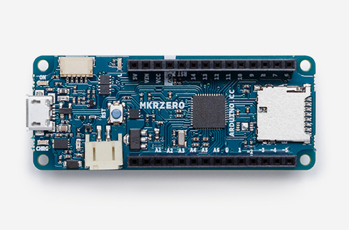
Meet the new MKRZero, the power of the Zero in a smaller board!

Say hello to the newest member of the Arduino family! The MKRZero–now available on our stores at the price of $21.90/€20.90 (+ tax)–shrinks the functionality of the Arduino Zero down into an Arduino MKR1000 form factor, making it a great educational tool for learning about 32-bit application development.

Like the Zero, the latest board is based on a Microchip SAM D21 ARM Cortex®-M0+ MCU. An integrated SD connector with dedicated SPI interfaces (SPI1) allows you to play with files without any extra hardware, while an analog converter enables you to monitor its battery voltage.

The MKRZero’s features in a nutshell:

  • small form factor
  • number crunching capability
  • low power consumption
  • integrated battery management
  • USB host
  • integrated SD management
  • programmable SPI, I2C and UART

Interested? You can explore the MKRZero in more detail, including its technical documentation, via the links below:

On the software side:

  • If you use the Arduino IDE, you will need to add the new Intel SAMD Core, selecting Tools menu, then Boards, and last Boards Manager on the Arduino Software (IDE).
  • If you use Arduino Web Editor, everything is already updated!

Watch out music makers, we’ve got some news for you! We have released two libraries for your enjoyment:

  • Arduino Sound library – a simple way to play and analyze audio data using Arduino on SAM D21-based boards.
  • I2S library – to use the I2S protocol on SAMD21-based boards. For those who don’t know, I2S (Inter-IC Sound) is an electrical serial bus interface standard for connecting digital audio devices.

Buy a brand new Arduino MKRZero now!

Join the discussion on the Arduino Forum!

FR4 Machine Shield Is A CNC Milling Machine From FR4 PCB

The people behind the PocketNC heard you like CNC PCB mills, so they milled you a PCB mill out of PCB. They announced their surprising new open source hardware product, a pocket sized 3-axis CNC machine entirely made out of FR4 PCB material, aptly named “FR4 Machine Shield”, at this year’s Bay Area Maker Faire.

We know the concept from quadcopters, little robots, and generally things that are small enough to make use of their PCBs as a structural component. But an entire CNC machine, soldered together from a few dozen PCBs certainly takes it to the next level.

There is no doubt that 2mm thick fiber reinforced epoxy can be surprisingly rigid, although the Achilles heel of this method might be the solder joints. However, it looks like all load bearing, mechanical connections of the machine are supported by tightly interlocking “dovetail”-joints, which may help protecting all the solder connections from the strain hardening effects of continuous stress and spindle vibrations.

As you might expect, most of the wiring is embedded into the FR4 frame construction, and to squeeze the maximum value out of the PCB material, the motor driver boards interface via card edge connectors with the (currently Arduino based) controller board. In addition to the milling head, which features a brushless DC motor and a tool coupler, the team wants to develop heads for circuit printing, microscopy, pneumatic pick and place, hot air reflow, and 3D printing.

With all those cost-driven design choices, from the one-step manufacturing process of the frame and wiring to the dismissal of screws and nuts from the frame assembly, the “FR4 Machine Shield” could indeed become one of the cheapest CNC machine kits on the market. The team targets an introduction price of $400 during a Kickstarter campaign in June 2016. Can they deliver? [Gerrit] check Pocket NC out at the Faire and ended up raving about how they run their business.

Enjoy their teaser video below!


Filed under: cnc hacks

Why I Go Through So Many Arduinos

I make things for people that can’t be bought off a shelf, and in the past several years I have gone through a lot of Arduinos. More and more, they are simply the right tool for both the job and the client. This wasn’t always the case; what changed?

My clients today still include startups and other small businesses, but more and more they’re artists, hobbyists venturing into entrepreneurship, or people who make one-offs like the interactive displays you find in museums or science centers. The type of people I work for has changed, and because of this, the right tool for their job is almost always an Arduino.

If Not Arduinos, What?

I was chatting with some new people at a local hackerspace, and we were talking about what we do. I told them I spent a lot of time making one-off devices, prototypes, or small production runs for people who know what they need, but can’t buy it off a shelf. I mentioned that I go through plenty of Arduinos as a result.

“What would you be using if it wasn’t an Arduino?” I was asked.

I thought for a moment and replied something about how I’d probably use an AVR on a board I designed, and roll that out when I needed a microcontroller to do things. I said this because that board was my go-to solution when I needed something for my own projects. There was a nod and the conversation moved on, but after thinking a moment more I realized I had to change my answer.

If I wasn’t using an Arduino, what would I use? Probably nothing. Because the job wouldn’t exist.

The Arduino is the Right Tool for Their Jobs

Prototypes for a mesh wireless client project. Arduinos inside.

A lot of my work looks like this: the client comes in with an idea but it’s not quite there, and it needs some development before it can become a product. First I build a proof of concept, but then we often move to iterative prototypes where we do a lot of testing and measuring. What is learned from one prototype is rolled into subsequent prototypes in a continuous flow of learning and refinement. (The following saying applies to this process: “Developing hardware is just like developing software, except that every time you hit ‘compile’ it takes weeks and costs thousands of dollars.”)

Eventually, we reach the end of what’s possible with the Arduino and readily available components. Then it’s time for the engineers to design a solution: something focused directly around exactly what was discovered, with minimal waste. That engineered solution is not very likely to include an Arduino.

But until we hand the job off to the engineers, the Arduino was part of the solution. And a big reason for that is the comfort level of the client during this phase of iterative refinement. A lot of clients would throw up their hands at an AVR-ISP or a hex file but they know what an Arduino is. They are often comfortable uploading sketches and making changes to them, or even following a wiring diagram. They probably even prototyped their idea with an Arduino. Using an Arduino allows them to remain hands-on with the development of their idea, even as they outsource some of the work to consultants.

The Clients have Changed

Sticking with what the client knows and expects is often the right move but there’s another, deeper reason that an Arduino is even involved in the first place. Without the Arduino and the whole ecosystem of open and accessible hardware and tools that has grown along with it, many of my clients would probably never have even begun to develop their ideas. They certainly would never have gotten to the point of hiring me for my help.

Custom ultra-slow speed turntable used to capture high magnification video for Broken Sound by Gary James Joynes

The observation that I was going through a lot of Arduinos also made me realize that my clients had changed. I now work more with artists who are incorporating electronics into their work in ways that weren’t accessible just a few years ago, basement inventors who are taking the plunge to see if their idea will fly, people who need small production runs of 10-100 in a world where “small” often means thousands, and stage magicians who need someone to help them make the next great trick happen. (I hadn’t expected that last one, but you better believe that market exists.)

All of these clients need someone to handle the hard or time-consuming parts of something they otherwise grasp, or someone to make them something they can plug in to the rest of their work. They don’t always have much of a budget to work with, but they do have enthusiasm and they know what they want. They’re idea people who roll up their sleeves and get their hands dirty, and they weren’t around in the numbers that they are now.

There’s one more advantage to working with these types of folks: when people have experience with developing their own solutions and experience running into the roadblocks, they usually also have some understanding of and appreciation for the kind of time, work, detail, and costs that go into development. Those of you who have done professional development work will recognize what a boon that is.

I’ve done custom work for many people over the years, but change is constant. It’s a big world and I’ve only worked in and seen my piece of it. Have you found things to be as I described, or different? Is my experience somehow unique? Post up in the comments!


Filed under: Curated, Featured, Interest, Original Art

Certifying open-source hardware? OSHWA seeking feedback

The Open Source Hardware Association (OSHWA) is seeking feedback on a proposal for the certification of open-source hardware. The certification would provide a more formal means of verifying the compliance of a particular project or organization with the practices of open-source hardware, as understood by the community. There are, however, many different ways in which such a certification process could work, e.g. whether it should include a single standard for open-source hardware or recognize multiple levels of openness; whether people should be able to self-certify or if OSHWA would need to pre-approve certifications; etc. OSHWA is seeking feedback from the broader open-source hardware community in order to help refine the certification proposal.

You can see the full proposal here and provide feedback on the OSHWA forums.

An open hardware quartz crystal microbalance for ultra high mass sensitivity

Marco Mauro is a physicist currently employed as Scientific Coordinator at Novaetech, the first Spin-off Company of the National Institute for Astrophysics (INAF) in Italy. He shared with us all the info about a project he’s been working on  and based on Arduino Micro.

OpenQCM is a fully open source scientific microbalance capable of weighing mass deposition down to 1 billionth of gram:

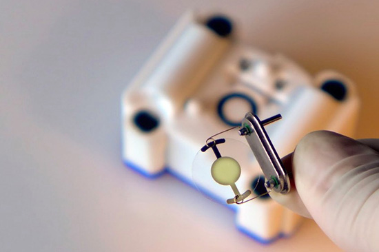
The sensing core of the microbalance is a piezoelectric quartz crystal oscillator. The deposition of a very tiny mass on the surface causes the variation in the quartz frequency. openQCM belongs to a new generation of innovative smart sensor which boast high resolution and ultra high mass sensitivity. The open source strategy made the creation of openQCM available at low cost which represents a bit fraction of the cost of similar scientific products.

openQCM was built keeping in mind the emergent principles of the open source hardware movement. The open source hardware gives people the freedom to control their technology through the open exchange of all the project features, 3D design, electronics and software. The open hardware potentiality is even greater when it comes to hardware for scientific applications.

openQCM is exactly something like that, the first open hardware quartz crystal microbalance with applications in a wide range of scientific fields, such as chemical and biological sensing, material science.

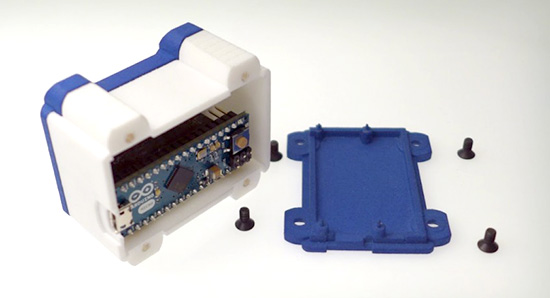
openQCM has an Arduino Micro board inside at heart. By hacking the timer counter of the AtMega32U4 Arduino microcontroller, it is possible to measure the quartz crystal frequency variations using the 16 Mhz microprocessor clock. openQCM team has designed an Arduino Micro shield with an embedded quartz crystal oscillator driver circuit and a temperature sensor. The output of the quartz crystal oscillator driver is fed to the Arduino Micro timer counter and the analog value of the temperature sensor is fed to the analog pin of the board. This configuration allow you measure the quartz crystal frequency with a resolution of 1 Hz, which roughly corresponds to a mass resolution of 700 pg over the entire quartz surface in air.

One of the major challenge of an open hardware project is that such devices require funding to prototype and manufacture. That’s why the openQCM team have selected the 3d printing technology to keep high quality and low cost. Using 3d printing to print out the prototypes via the SLS process from OS Formiga P100, P110, P395, and P730, the openQCM team created the device’s parts, which required a precision down to 60 µm.

The open source concept made openQCM publicly available so that anyone (scientists, technology enthusiast, makers, hobbyist …) can study, modify, and develop the hardware based on the original design. openQCM is now working and ready to win the heart of the scientific community and more.

Go and make one yourself!