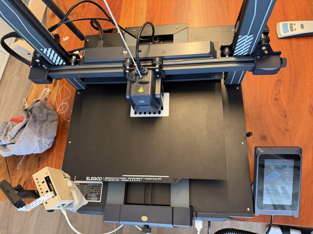
A lot of newer 3D printers incorporate sophisticated sensor suites and cameras to detect problems with print jobs, like the dreaded “spaghetti failure.” Those work pretty well and prevent wasted time, wasted filament, and even damage to the printer. But what if you don’t have a printer with those features? Or if you want to protect your privacy? Then you can follow Philipp Schweizer’s guide to use an Arduino UNO Q as your local 3D printing watchdog.
Schweizer’s approach is to use the UNO Q and a camera to detect anomalies, rather than specific problems. It doesn’t look for spaghetti failure or clogging. Instead, it looks for a normal print. Anything abnormal gets flagged. That dramatically reduces the amount of training data required and accounts for all visible issues, whether they were anticipated and trained for or not.
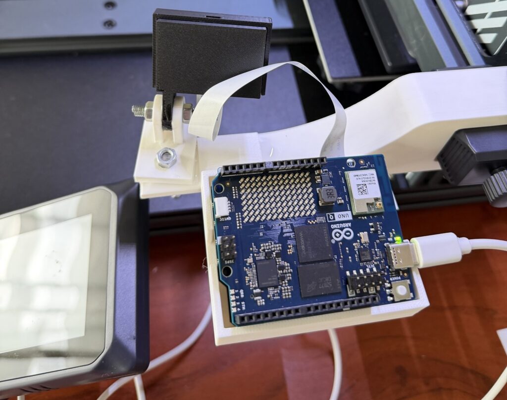
The hardware required for this includes an UNO Q (4GB model), an Arduino®UNO Media Carrier, an V2-style IMX219 camera module, and a custom-printed mount with fasteners. The goal with that mount is to point the camera at the hot end and below, so it will likely require customization to fit the 3D printer model in question.
All of the magic happens thanks to the FOMO-AD anomaly model from Edge Impulse, implemented through Arduino App Lab. That requires training on images of normal prints and Schweizer explains how it is easy to collect those automatically during print jobs. By keeping the image resolution low (632×480), the overhead remains minimal and the model efficient.
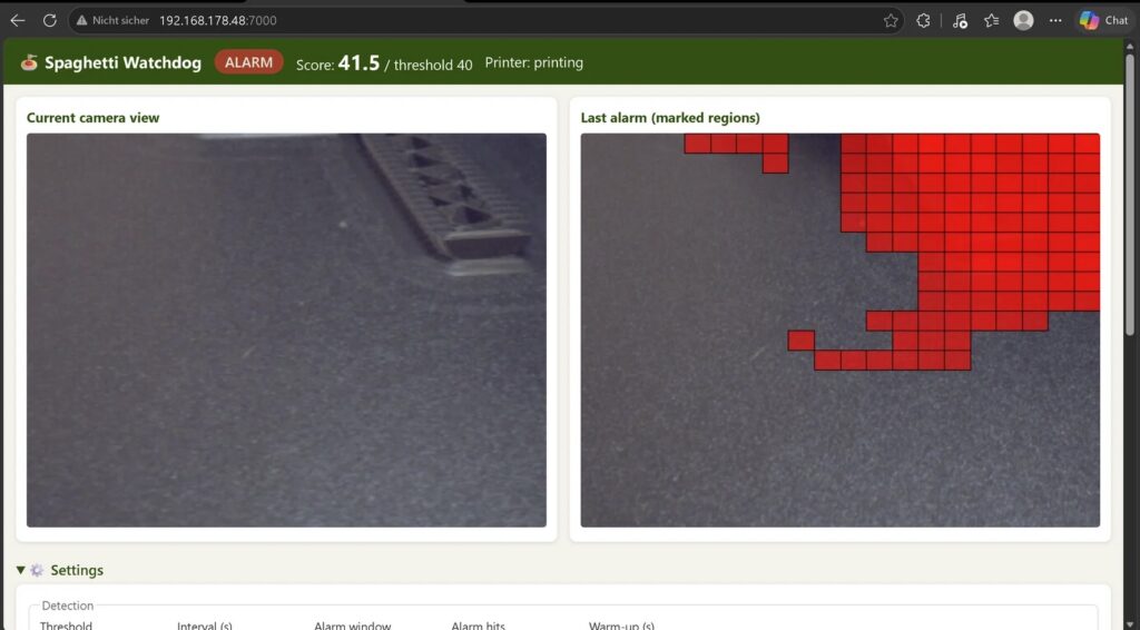
As Schweizer points out, an overeager watchdog is worse than not having a watchdog at all. For that reason, Schweizer built his app so that it only automatically pauses a print if at least three out of the last four images show an anomaly. When that is the case, it pauses the job through the Moonraker API (standard for Klipper-based systems). For those who don’t use Klipper, it is possible to integrate the watchdog into Octoprint or other control software. It also sends an MQTT message compatible with Home Assistant for notifications and hosts a webpage where the status is visible.
All of that works without leaving the local network, so it is great for those who value privacy and security. Even if those factors don’t concern you, this is an affordable watchdog solution that doesn’t require a specific 3D printer model or a subscription service.
Physical AI is based on the idea that intelligence shouldn’t stop at perception: instead, it should bring to life systems able to sense their environment, reason about it, and act on it – all in one continuous loop. It’s what makes the difference between a device that observes and one that acts.
Autonomous mobile robots are one of the clearest expressions of that idea in the real world. Imagine an autonomous delivery robot working around a warehouse, carrying items to the correct shelf or placing them on a conveyor belt for inspection or packaging. On its way, it may have to stop as someone steps into its path, or adjust its route if a cart has been moved. It must understand its surroundings, determine its position, calculate a path, and respond as the environment changes, until it reaches the right destination.
It must control its wheels precisely, read sensors continuously, and react quickly to nearby obstacles – all at the same time.
In all autonomous mobile robots, or AMRs, these tasks require two different kinds of computing: navigation, computer vision, and AI benefit from the flexibility and performance of Linux; motor control and time-sensitive sensor management require the responsiveness of a microcontroller.
VENTUNO Q brings these two worlds together, combining a Linux-capable MPU with a real-time MCU on a single platform. To explore the potential of this architecture, let’s imagine how it could become the central computing platform for a food-delivery AMR, where perception, ROS 2, Edge AI and physical control could work together.
Two computing worlds, one robot
In a conventional AMR prototype, high-level computing and motor control are often distributed across separate boards. A Linux computer runs ROS 2 and processes data from cameras and LiDAR, while a microcontroller manages motors, encoders and local sensors. This approach works, but it also creates integration work. Developers must connect the boards, define their communication protocol, maintain multiple development environments and debug the interaction between systems designed independently from one another.
VENTUNO Q provides a more integrated starting point. Its MPU can host Linux, ROS 2, navigation software, computer vision and AI workloads. Its MCU can remain close to the physical robot, managing wheel control, encoder feedback, inertial measurements, short-range sensing and communication with motor drivers. The separation of responsibilities is clear: the MPU determines where the robot should go, while the MCU turns that decision into controlled physical movement. Together, the two sides allow the system to sense, decide, and act.
Sense: giving the robot an understanding of its environment
As the delivery robot travels through a warehouse, hotel, or even a restaurant or public space where it is at work to deliver orders, it must continuously build a picture of what is happening around it. No single sensor can provide all the information it needs, so the architecture combines several complementary sources.
A 2D LiDAR can provide the geometric foundation for navigation. Its laser scans describe walls, corridors, furniture and other structures around the robot. Combined with wheel odometry and inertial data, these scans can be used by SLAM software to build a map and later help the robot estimate its position within it. However, a LiDAR scanning on a single plane cannot describe every obstacle. A table surface, an open drawer or an object protruding into the robot’s path may sit above or below that plane.
A stereo-depth camera can add three-dimensional information, helping the robot perceive shapes and obstacles that may not appear clearly in a planar scan. A MIPI camera can provide visual input for more application-specific tasks, such as detecting people, recognizing a delivery station or checking whether a tray is present.
Image shown for illustration purposes only
Closer to the robot, an Arduino® Modulino Distance node monitors blind spots or detects objects immediately in front of the chassis. A Modulino Movement provides acceleration and angular-rate data, contributing to motion estimation and helping identify unusual vibration, collisions or unexpected movement.
Wheel encoders complete this picture by measuring how the robot is actually moving. The MCU can use their feedback to regulate wheel speed, while the resulting odometry can be shared with the navigation software running on Linux. Rather than relying on a single “smart” sensor, the robot develops awareness by combining geometric, visual, inertial and mechanical information.
Decide: ROS 2 as the software backbone
On the MPU, ROS 2 provides a common software environment for connecting all these elements. The LiDAR publishes laser scans. The camera pipeline provides images or depth information. The robot publishes odometry and inertial measurements. Navigation components consume this data to estimate the robot’s position, plan a route and respond when the environment changes.
Image shown for illustration purposes only
During its first exploration of a space, a ROS 2 SLAM package can combine LiDAR data and odometry to create a map. Once that map is available, the robot can localize itself and use Nav2 to move between destinations.
If the application sends the robot from the warehouse to the packaging station, Nav2 calculates an appropriate route and continually updates it as new sensor information arrives. It then generates velocity commands describing how quickly the robot should move forward and rotate. Those commands express the intended movement, but they do not directly control the motors. That responsibility moves from the Linux domain to the MCU.
Act: from a ROS 2 command to wheel movement
When Nav2 publishes a velocity command, an MPU-to-MCU communication layer transfers the request to the real-time control application. The MCU translates the requested linear and angular movement into targets for the left and right wheels. It then communicates with the motor controllers – potentially over CAN – and uses encoder feedback to maintain the required wheel speed.
This control loop can run with predictable timing, independently of the larger ROS 2 software graph operating on Linux. Information also travels in the opposite direction. Encoder measurements, inertial data, short-range distance readings and drive-system diagnostics can move from the MCU to the MPU, where they become available to the ROS 2 application.
This connection between the two computing domains is one of the most important elements of the architecture. It allows high-level navigation software to interact with the physical robot without asking Linux to manage every time-sensitive electrical and mechanical detail.
It also creates space for local reactions. If a close-range sensor detects an object immediately in front of the robot, the MCU can place the drive system into a controlled stop state and report the event to the MPU. The navigation layer can then reassess the situation, update the route or notify the application. The result is a robot in which intelligence and responsiveness complement one another.
Adding context with edge AI
LiDAR, odometry and Nav2 can already allow the robot to navigate through a mapped environment. AI becomes valuable when the robot needs to understand the meaning of what it perceives. The navigation system may detect an obstacle, for example, but a vision model could determine whether that obstacle is a person, a chair or a delivery cart. This additional context enables more appropriate behavior.
When a person approaches, the robot could slow down, wait or announce that a delivery is arriving. At its destination, a visual model might recognize the delivery zone or check whether someone has removed the tray. The same platform could also inspect the route for objects left on the floor or use vibration data to identify abnormal mechanical behavior.
Edge Impulse offers one possible workflow for developing this kind of application-specific intelligence. Through its ROS 2 integration, an inference model can consume image data and make its results available to other parts of the robotic application. ROS 2 helps the robot decide how to navigate. Edge AI helps it interpret the context in which that navigation takes place. And with the integrated Edge Impulse platform, you can choose to deploy directly into Arduino® App Lab – it just takes one click.
Growing the prototype one capability at a time
Although the reference architecture includes navigation, depth sensing and AI, a developer would not need to introduce every capability at once. The first prototype could focus only on the mobile base, with the MCU controlling the motors and reading the wheel encoders. Once basic movement is reliable, the control layer could be connected to ROS 2 on the MPU so the robot can accept standard velocity commands and return odometry data.
Adding LiDAR would introduce mapping, localization and autonomous navigation. Depth sensing and short-range sensors could then improve obstacle awareness. Finally, visual AI could transform the generic mobile platform into a delivery robot capable of recognizing people, destinations and application-specific events. This progressive approach keeps each development step understandable while preserving a clear path toward a more capable system.
VENTUNO Q does not remove the engineering challenges involved in building an AMR. Mechanical design, power management, motor sizing, navigation tuning, sensor placement and safety still require careful work. Its value is in providing a more coherent place to begin.
From perception to motion
A food-delivery robot is only one expression of this architecture. The same computing model could support warehouse vehicles, inspection robots, hospital logistics systems, agricultural platforms, and other autonomous machines.
The sensors, drive systems and AI models may change, but the fundamental challenge remains the same: connecting high-level intelligence with responsive physical action. By combining a Linux-capable MPU and a real-time MCU, VENTUNO Q gives developers a platform for exploring that complete chain. ROS 2, navigation, perception and edge AI can operate on the MPU, while the MCU manages the sensors and actuators that connect software decisions to the real world.
From understanding the environment to controlling the wheels, VENTUNO Q offers a unified starting point for prototyping the next generation of intelligent mobile robots.
VENTUNO Q is available through our official distribution partners: DigiKey, Farnell, Mouser, Robu.in, and RS, along with our other authorized distributors and resellers.
Arduino, Modulino, VENTUNO, and the Arduino logo are trademarks or registered trademarks of Arduino S.r.l.
Upline is a minimal serial protocol that turns any microcontroller into an IoT device. The project sheet describes a system based on newline-delimited ASCII records, with a complete Arduino implementation in a single header. The project, by smlcrft, targets 8-bit chips with very limited resources.
The operation is simple. The byte stream is split into lines using LF or CR terminators, ignoring empty lines and those that do not start with the ‘^’ character. Each line is a list of independent entries, delimited by the same ‘^’ character. Each entry represents an operation on a specific key.
How the Upline protocol works
Entries are only processed if fully delimited by two carets. This way partial data is never applied, and an interrupted communication does not leave the device in an inconsistent state. Writes are confirmed via an echo of the value actually in use: this distinguishes a rejection from a loss of communication.
A periodic heartbeat demonstrates that the device is alive and speaks the Upline protocol. This limits the receiver’s wait time, which immediately knows if the node is operational. The protocol also supports escaping special characters with six symbolic sequences, and does not require floating-point numbers: it uses the fixN format for decimals.
4,060 bytes of flash on ATmega328P, 358 bytes of SRAM
3,168 bytes of flash on ATtiny85, 253 bytes of SRAM
2,100 bytes of flash on ATtiny85 in transmit-only mode
98 bytes for a universal line reader on ATmega328P
The numbers are remarkable for a complete protocol. On ATmega328P, 4,060 bytes of flash and 358 bytes of SRAM are needed. On ATtiny85, consumption drops to 3,168 bytes, and in transmit-only mode to 2,100 bytes. The project sheet also reports 98 bytes for a universal line reader on ATmega328P.
Why Upline matters to makers
Upline lets you turn any microcontroller into an IoT device with a minimal, efficient, and robust protocol. The philosophy is the opposite of heavy frameworks: here everything fits in one header and runs even on 8-bit chips with only a few hundred free bytes. An Arduino Nano ESP32 board can use the same protocol as an ATtiny85, simplifying communication between heterogeneous nodes.
The protocol is particularly suited to those building distributed sensors, remote actuators, or small monitoring nodes. Moreover, the echo confirmation makes the system reliable even over noisy radio links. To connect a node to a PC and read the record stream, just use a 3.3 V / 5 V USB-serial converter: Upline speaks over any UART.
Getting started with Upline
To start, simply download the upline-arduino header and include it in an Arduino project. The fact sheet lists support for ATmega328P, ATtiny85, SAMD21, ESP32, and RP2040, among others. An Uno R3 with an ATmega328 is a great test bench to learn the protocol without soldering anything: those are the 4,060 bytes of flash measured by the author.
The source code is a single header file, so integration is immediate. No external libraries or complex build tools are needed. A USB ATtiny85 board is instead the project’s edge case: 3,168 bytes of flash and 253 of SRAM, and the protocol fits entirely inside.
Finally, the project documentation reports precise numbers for each configuration. This helps choose the right microcontroller based on flash and SRAM budget. For the smallest projects, transmit-only mode on ATtiny85 requires just 112 bytes of SRAM.
Building a motorized welding turntable solves a common problem: welding around circular or cylindrical objects without walking around the workpiece. Greenhill Forge’s project creates a large motorized lazy Susan with adjustable speed and a modest budget. The table rotates the piece under the torch, so the welder stays still and both hands are free to guide the arc.
The heart of the system is a stepper motor mounted under the table surface. Rotation passes through a gear reducer and a standard spider coupling, which transmits motion to the top plate. The reducer increases torque and lowers speed, so the table moves smoothly even with heavy parts. Everything is controlled by an Arduino UNO Rev3 board, which drives the motor and reads user commands.
Speed control and user interface
The user adjusts rotation speed with a rotary encoder. The knob is comfortable to use even with welding gloves. A small OLED screen shows the set speed, so control is immediate and precise. The firmware on the Arduino UNO reads the encoder, updates the display, and drives the stepper motor with the correct pulse frequency.
For those who want to replicate the project, choosing components is straightforward. A Uno R3 with ATmega328 is the same board used in the original project. A NEMA 17 stepper motor rated at 1.2 A has the right torque for a table of this size, which rotates through a reducer anyway. A 12 mm rotary encoder with knob connects directly to digital pins and can be turned even with welding gloves. Finally, a 128×64 OLED display shows parameters clearly.
Stepper motor with gear reducer for torque
Spider coupling to connect shaft and table
Lazy Susan bearing for rotating support
Rotary encoder for adjustment
OLED display for visual feedback
Grounding through the shaft
An important detail is grounding management. In welding, current must return to the generator through the workpiece. If the turntable is not grounded, current passes through the lazy Susan bearings, causing arcs that damage them quickly. Greenhill Forge solves the problem with a ground strap that runs through the motor shaft.
The strap maintains conductivity between the table surface and the workpiece. This way, welding current has a dedicated path and the bearings stay protected. The strap is a wear item, but with normal use it should last a long time. Also, replacement cost is minimal, so maintenance stays economical.
The project is documented in a Greenhill Forge video, which follows the entire process: cutting and welding the frame, mounting the motor under the table, and grounding. At the end, the table is shown in action during a real weld, with speed adjusted on the fly.
Why build a turntable
This project appeals to both beginners and experienced welders. Construction is simple and requires few tools. Moreover, electronic control with Arduino UNO opens the door to future modifications, such as programmed rotation or foot pedal control. The modest cost makes the project accessible to many makers.
The welding turntable is an example of how a stepper motor, an encoder, and an OLED display can turn a simple support into a professional tool. Well-designed grounding protects components and ensures quality welds. Finally, adjustable speed lets you adapt rotation to any type of work.
Let’s get to know and learn how to use a board for RF tag identification, easily paired with Arduino.
We have covered radio-frequency identification, better known as RFID, several times before; for example, in issue no. 254 we dedicated an in-depth look at it with a thorough theoretical introduction and some usage examples based on the RFID PN522 module, accompanied by the ever-present Arduino board. In this article, we pick up the discussion again by experimenting with another module, the RFID-RC522, based on the MFRC522 chip produced by NXP (the datasheet is available at the web link https://www.nxp.com/docs/en/data-sheet/MFRC522.pdf).
The RFID-RC522 module
The MFRC522 is a highly integrated RFID reader/writer for contactless communication at 13.56 MHz, supporting the ISO/IEC14443A/MIFARE and NTAG standards.
The transmitter inside the MFRC522 can drive an antenna designed to communicate with cards and transponders without additional active circuits. The internal receiver can efficiently demodulate and decode signals from cards and transponders compatible with the standards listed above.
The MFRC522 supports the MF1xxS20, MF1xxS70, and MF1xxS50 models. It also supports contactless communication with MIFARE transfer rates up to 848 kB (kiloBaud) in bidirectional mode.
The MFRC522 is compatible with all variants of the MIFARE identification protocols MIFARE Mini, MIFARE 1K, MIFARE 4K, MIFARE Ultralight, MIFARE DESFire EV1, and MIFARE Plus RF, grouped under the generic term MIFARE.
Below we summarize the main technical features of the module:
analog circuit to demodulate and decode responses;
buffered drivers for connecting an antenna with a reduced number of external components;
supports ISO/IEC 14443 A/MIFARE and NTAG;
typical operating distance in read/write mode up to 50 mm depending on antenna size and tuning;
supports MF1xxS20, MF1xxS70, and MF1xxS50 encryption in read/write mode;
supports ISO/IEC 14443 with high transfer rate communication up to 848 kbaud;
supports MFIN/MFOUT;
additional internal power supply to the smart card IC connected via MFIN/MFOUT;
supported host interfaces: SPI up to 10 Mbit/s, I²C-Bus up to 400 kBd in Fast mode, up to 3400 kBd in High-speed mode, serial UART RS232 up to 1,228.8 kB/s, with voltage levels depending on the pin supply voltage;
the FIFO buffer manages sending and receiving at 64 bytes;
flexible interrupt modes;
hard reset with low-power function;
software power-down;
programmable timer;
supply voltage from 2.5 to 3.3 V;
programmable I/O pins.
The RFID-RC522 module is detailed in Fig. 1, where you can see all the available connections.
Fig. 1 The RFID-RC522 module
Connecting to Arduino
Since all current libraries for using the module with Arduino reuse the SPI connection, we will focus only on that; Fig. 2 illustrates the connection to make for the subsequent tests with Arduino UNO.
Fig. 2 RC522_ISP connections
In Table 1 we describe the connections analytically with their signals: on the left are those of the Arduino UNO and on the right the contacts of the RFID-RC522 module with the corresponding wire colors in the diagram in Fig. 2. The IRQ pin of the RFID module should be left unconnected because we do not manage it in this project and do not need it.
Table 1 Connections between the RFID-RC522 module and Arduino
Of course, you must be very careful, because swapping just two wires will cause the module to fail; another important thing is power: the module requires 3.3 V, and the corresponding pin on Arduino is right next to the 5 V one; a moment of distraction would almost certainly damage the module.
The board (the RFID module used in the project) comes with two 8-pin strip headers (one straight and one at 90°) to solder as you prefer into the appropriate signal holes, an RFID Tag Card, and an RFID keychain Tag for initial testing.
Libraries for RC522
Using this module is made easier by the availability of specific libraries, of which we have selected two: the one from Velleman and the one written by Miguel Balboa.
Velleman: it is a minimal library consisting of only two files (RFID.h and RFID.cpp). Once downloaded from the link: https://www.velleman.eu/downloads/29/vma405_library.zip, you need to include it by opening a new sketch with an updated version of the IDE (in our case 1.8.12). Run the command Sketch – Include Library – Add .ZIP Library… and select the .zip file (Fig. 3), then close the IDE; it will be available when you reopen it.
Its inclusion in the IDE is done in the same way as seen before. This library is quite demanding and requires considerable skills in RFID and programming to exploit it, so we only point it out to more experienced readers, while for the test we will see later we will use the one distributed by Velleman.
Functionality test
Let’s start with a test to verify the connections and the correct installation of the vma405 library. We have prepared a sketch named “RFID_TAG_CODE”; open it in the IDE and upload it to the Arduino UNO, then open the Serial Monitor, which will show the message “Avvicina un Tag al Modulo” (Bring a Tag close to the Module); at this point, bring the Tag close to the part of the module where the radio wave symbols are silkscreened (Fig. 4).
Fig. 4 Reading a Tag with the RC522 module
Keep in mind that the module should always be kept away from devices that can generate electric or electromagnetic fields, otherwise it might not work correctly.
The moment the Tag is recognized, the module reads its UID (unique identification code) and displays it on the Serial Monitor, both in decimal and hexadecimal format; in Fig. 5 we can observe the successive reading of two Tags.
Fig. 5 Reading the UID of two Tags
If after the first identification you bring the same Tag close again, nothing will happen because we have not included an alternative action in the sketch; bringing another Tag close instead will give its UID in both formats.
When this test succeeds, you need to decide which Tag will be the “System Administrator” of the circuit we have prepared for experimenting with this module and note the five decimal numbers that make up its UID. For our example, we will use the first group visible in the figure (197, 5, 190, 35, 93).
Access control project
With the help of a breadboard and very few other components, let’s now build a circuit to simulate an access control system using RFID technology with our RC522 module.
The sketch we have prepared can be downloaded and is called Access_Control.rar; it consists of two tabs, and the folder obtained from decompressing the file must be placed in the sketch folder of your IDE; the vma405_library must have been installed beforehand.
The idea is a hypothetical access control system, where the acceptance of a Tag is indicated by the alternating on/off of a blue LED, while rejection is represented by a red LED turning on for about 3 seconds.
Authorized Tags are pre-stored in the EEPROM of the Arduino microcontroller; our sketch supports up to three, but they can be increased up to the availability of the EEPROM. Storage only happens with prior authorization from the “System Administrator,” who has an RFID CARD Tag whose UID must be manually entered in the sketch and which, once read by the module, allows other Tags to be brought close to accredit them and store them in the EEPROM.
From this point on, when you bring an authorized tag near the module, the blue LED will turn on or off with each pass, toggling its state. The red LED, on the other hand, will light up for three seconds when someone tries to gain access with an unregistered tag, effectively denying authorization, and then it will turn off.
Before uploading the sketch to the Arduino, you need to open it and assign the corresponding decimal values of the chosen tag’s UID to the five variables dec_code0 through dec_code4 (Fig. 6), replacing the pre-stored values you will find there.
Fig. 6 Entering the administrator UID in the sketch
At this point you can upload the sketch to the Arduino and then disconnect the USB cable to remove power. Next, move on to building the practical layout shown in Fig. 7, which explains how to connect all the required components.
Fig. 7 Wiring diagram of the access control
Required materials
The materials needed to build the project are:
RFID-RC522 module
Arduino UNO
Breadboard with side power rails (red and black, or red and blue)
6×6 mm push button
Red LED
Blue LED (or another color of your choice)
2 resistors of 220 Ohm
1 resistor of 10 kOhm
5 M-M jumper wires
7 M-F jumper wires
1 jumper bridge, 3-pin
1 jumper bridge, 5-pin
1 jumper bridge, 19-pin
4 tags, one of which marked as administrator
Note that regarding jumper wires and bridges, we provided the list to replicate our exact practical layout; of course you can make any variation, as long as you correctly make the proposed connections, otherwise the circuit will not work. Above all, be extremely careful not to reverse the power supply (3.3V and GND), otherwise you risk burning the module!
A special note about the breadboard: during our tests we came across a model with the power rails interrupted in the middle section. This was actually clearly indicated by the break in the red and blue silkscreen lines, but since it is unusual, we initially did not notice it. As a result, the RC522 module’s LED still turned on (due to current carried by the signals), but tag reading did not work. We therefore had to add two jumper wires to connect the two rails along their entire length (Fig. 8), i.e., to bridge them.
Fig. 8 Detail of the connection of the breadboard power rails
How the access control works
Once the circuit is complete on the breadboard and the connections are checked, to begin simply reconnect the USB cable from the PC to the Arduino UNO board. You will see the RC522 module’s red LED light up (but as explained earlier, this does not indicate correct power supply), while the two red and blue LEDs on the breadboard remain off.
Now open the Serial Monitor of the Arduino IDE, and the message “Controllo accessi attivo” will appear. The first operation to perform is to bring the Administrator tag near the module. If everything is in order, the two LEDs will blink simultaneously three times and remain on; the Serial Monitor will also show the message visible in Fig. 9, indicating that Administrator mode is active.
Fig. 9 Administrator mode
If at first power-up a number other than 0 appears (usually it will be 255), you need to reset the EEPROM. Simply press the push button mounted on the breadboard to achieve the desired result (Fig. 10).
Fig. 10 EEPROM reset
After the reset, you will exit Administrator mode and the LEDs will turn off. You must pass the Administrator tag again to re-enter, then simply bring the tag you want to authorize near the module to store its UID (Fig. 11).
Fig. 11 Storing an authorized tag
This operation can be performed for a maximum of three tags; after that, no more can be stored unless you modify the sketch accordingly.
Daily use of the system
At this point we can observe the circuit’s behavior depending on the type of tag we bring near the RFID reader; there are two possibilities.
Unregistered tag: the red LED turns on for about three seconds, then turns off; authorization is denied.
Registered tag: if the blue LED is off, it turns on, indicating that authorization has been granted; the LED stays on until you pass the same tag or another registered tag, at which point it turns off.
One last curiosity: if you lack other tags to simulate unauthorized access, you can use your own smartphone. If you have a phone with an NFC chip running Android 5.0 or later, simply enable NFC in the settings and then use the smartphone as if it were a tag.
In fact, when you bring it near the module with the chip side facing it, it will be recognized as a tag, but with a peculiarity that prevents its use as an authorized tag: with each new read, the UID turns out to be different from the previous read. This is easily verifiable with the “RFID_TAG_CODE” sketch. So even if you store the chip as authorized, it will not be recognized on subsequent reads.
In some rare cases, the smartphone may need a specific app to function as a tag. Simply download “NFC Tools” from the Play Store and leave it active, without doing anything else.
Conclusions
We end this article with a suggestion: as you can easily imagine, this project can be expanded by adding, for example, a relay driven by the same pin as the blue LED, which would allow you to activate an actuator such as an electric lock. The only limits are those of your imagination.
Naturally, the greater the complexity of the expansion, the more variations and implementations you will need to make to the sketch, but it will all be a useful programming exercise that will increase your skills and give you great satisfaction.
Contributor Pasquale Barrega, author of the YouTube channel Pasquale’s LAB, has published a series of four videos dedicated to the analog-to-digital (A/D) and digital-to-analog (D/A) converters built into the Arduino UNO R4 board. The journey starts from the basic concepts and arrives at the practical construction of an electronic voice changer, using just a few external passive components and a dynamic microphone.
The first experiment: digitizing the voice
In the introductory video “Audio applications with AD and DA converters”, Pasquale explains how to take the first steps in digitizing an analog signal, in particular the one coming from a microphone. The video illustrates the schematic for audio acquisition, the code based on the Arduino environment functions, and the first practical tests of reading from the A/D converter and writing to the D/A converter.
From digitized signal to sound: the D/A converter
In the second video, “Let’s listen to the voice from the DA converter”, the focus shifts to the D/A converter: the digitized human voice is played back, with an analysis of the resulting signal also on an oscilloscope. Pasquale also illustrates the changes to the schematic and the code needed to complete the acquisition-playback cycle.
Adapting the impedance with the internal op-amp
The third installment, “UNO R4: adapting the DAC impedance with the internal op-amp”, tackles a critical aspect: the output of the D/A converter has a fairly high impedance, so it is advisable to insert an adapter. Pasquale shows how to take advantage of the operational amplifier integrated into the board, both on the hardware connection side and on the firmware activation side, with a comparison of the noise before and after inserting the op-amp.
The electronic voice changer: the project synthesis
The last video, “Electronic voice changer”, puts all the previous pieces together to build a pitch shifter using the A/D and D/A converters of the UNO R4. The device can be used for audio effects or to alter the voice in situations where it must not be recognizable. Pasquale shows the updated wiring diagram, the test setup, several practical tests with voice and musical content, and finally the complete code.
A new open-source project demonstrates how to combine computer vision and robotics on a single board. The robot, about the size of a desk, detects a human face through locally executed machine learning and turns toward it in real time, working at roughly 10–15 frames per second. Everything runs on the new Arduino UNO Q, without relying on the cloud.
Dual-processor architecture
The operation leverages the hybrid architecture of the UNO Q, which integrates two distinct units. The Qualcomm MPU microprocessor, running Linux, executes the AI model and the control logic written in Python. The STM32 MCU microcontroller, running Zephyr RTOS, drives the PWM signal of the servomotors with real-time precision.
The two processors communicate via Bridge RPC, a protocol based on MessagePack over an internal serial link, with a round-trip latency of about 8 milliseconds. This way, heavy inference stays separate from the real-time path, keeping motor control deterministic.
Vision, control, and web interface
The face-following robot built on the Arduino UNO Q.
A USB webcam captures video, while a lightweight face-detection model locates the face in the frame. A proportional controller then converts the horizontal position of the face into differential commands for the wheels. The project uses two ready-made App Lab “bricks”: one for camera-based object detection, the other for the web interface.
In particular, the browser-accessible dashboard lets you monitor detections and adjust steering parameters in real time, without recompiling the code. Every change to the sliders takes effect immediately via Socket.IO, making the tuning phase quick.
Technical details and motion safety
The robot uses differential drive with two continuous-rotation servos: a 1500-microsecond pulse corresponds to stop, while lower or higher values determine rotation in either direction. Additionally, the system limits Bridge calls to a maximum of 20 Hz, because sending commands too quickly would block the serial link.
The project therefore includes several protections: a “coasting” mechanism that maintains the last known position when the face disappears for a moment, a watchdog that stops the robot if detections are interrupted, and an emergency stop that ignores rate limiting to halt the motors immediately. Classified as an intermediate-level project, it is fully documented and released under an open-source license.
We bring the connections of the STEMMA QT/Qwiic connector available on the Arduino UNO R4 WiFi to the outside, using a board that can host I²C-Bus devices and can be daisy-chained with others of the same type.
Among the new features introduced by the Arduino UNO R4, the WiFi version stands out with a small interface connector called STEMMA QT/Qwiic. For form-factor compatibility reasons, this connection did not find a place in the traditional headers compatible with UNO boards, but it is located on the left side of the ICSP.
The connector makes an I²C-Bus accessible according to the pinout shown in Fig. 1, which can be used to manage external devices such as displays, sensors, etc., as long as they support I²C communication.
Fig. 1 Position of the STEMMA QT/Qwiic connector on the Arduino R4 WiFi board.
The SCL and SDA lines, unlike what happens in previous Arduino boards based on Atmel processors (where they were shared with pins A4 and A5 of the standard Arduino header), are connected to a second (secondary) I²C bus. In fact, the Renesas chip used in the R4 makes two distinct I²C buses available. The second one must be managed, however, by calling the specific object Wire1, as will be explained later in this article. The connection was introduced in the Arduino R4 (only in the WiFi version) to quickly connect Sparkfun standard breakout boards to it, since the connector used, a 4-pin single-in-line PCB connector, is the one adopted by Sparkfun boards. Qwiic is an ecosystem of breakout modules and development boards equipped with a so-called Qwiic connector, and it combines the flexibility of I²C with the ease of use of ready-made compatible cables available on the market, making it simple to manage a chain of I²C-Bus devices through a single cable. In practice, this means that wiring Qwiic devices is as simple as connecting them in series, and that’s it. To facilitate the connection and provide physical support for the breakout boards, instead of leaving them “flying,” we thought of designing and proposing a small adapter board that has two connectors compatible with the STEMMA QT/Qwiic standard, creating a pass-through connection that allows interfacing devices on the board itself, but also using the I²C bus to connect other devices. The I²C-Bus connections are distributed on our board in rows of pads where you can insert strips to connect and mechanically support breakout boards. Everything will be clearer by analyzing the project’s electrical schematic, which you can find on this page.
Electrical schematic
Electrical schematic of the adapter board.
As you can see, it is something very simple, which in fact has no electronics but simply creates a series of electrical interconnections, making a pass-through I²C-Bus connection between input and output through the two 4-pin Sparkfun-type connectors, and which has four rows of four pads at 2.54 mm pitch, ready for soldering female strips or pin strips for sensors and various devices. Note that the layout on the printed circuit board provides that the rows of pads have contacts arranged differently from one side to the opposite one: we wanted this to allow mounting boards and especially displays (since the problem occurs, for example, with small OLEDs) that have a different arrangement of Vcc and GND, as well as SDA and SCL. Through the STEMMA QT/Qwiic connector, the power needed for the breakout boards to operate is taken from the Arduino UNO R4 board, thus achieving independent operation of the devices connected to Arduino. As you can see, the circuit is essential and basically only serves to carry connections. The nice thing is that having two JST connectors makes it possible to daisy-chain numerous I²C-Bus interface devices on multiple boards, since the one connected to the Arduino R4 can in turn be connected to a second board, the latter to a third, and so on, to host more elements. For the interconnection between the Arduino R4 and our board, and between multiple adapter boards, you can use a pre-wired cable with a 4-pin JST connector at each end, 1 mm pitch, available at Futura Elettronica. The adapter board we propose here can also be purchased ready-made from [Futura Elettronica](www.futurashop.it) with product code FT1732M.
Construction and use
Photo of the adapter board.
The small adapter board described here can be easily prepared by photoengraving once you have the two copper-side traces, however, given its really low cost, it is possible and convenient to buy it ready-made. To explain how to use it, we propose a basic application that involves acquiring information from a breakout board for barometric pressure and ambient temperature sensors, then displaying it on a small 0.96″ monochrome OLED display based on the SSD1306 controller; clearly, we are referring to two devices equipped with an I²C-Bus interface. The Arduino R4 WiFi connector to use is the one detailed in Fig. 2. To use a Bosch BME280 sensor on a breakout board with the Arduino R4 and the STEMMA standard, you must mount the small breakout board using the appropriate pin strips and following the intended orientation (Fig. 3 can help you, where you can also see in which position to mount it); be careful that if you do not respect the indicated position and orientation, the small board can be irreparably damaged.
Fig. 2 The JST connector for the Qwiic STEMMA connection to be used to connect our board.
Fig. 3 The adapter with an I²C BME280 sensor on a breakout board.
This is because, as mentioned, the rows of I²C-Bus pads inside the printed circuit board are arranged differently depending on which side they are on, to allow mounting all breakout boards available on the market, equipped with 2.54 mm pitch strip connections. On a second FT1732M adapter board, you must mount the small OLED display, which is a standard type and, more precisely, the one sold by Futura Elettronica with the code OLEDGVSCSD; the device must be applied as shown in Fig. 4 after soldering a 4-pin pin-strip to it and using the row of pads whose contacts are arranged as follows: GND, VCC, SCL, SDA.
Fig. 4 The STEMMA QT/Qwiic adapter with the 0.96-inch display module attached.
To implement communication with the BME280 breakout, you must first load the Adafruit_BME280 library into the Arduino IDE; to do this, open the IDE, go to the Sketch menu, and issue the Include Library > Manage Libraries… command. At this point, search for “Adafruit BME280” in the search bar and install the corresponding library. Installation can also be done from a .zip file containing the library, using the appropriate menu command. Then, from the File menu, you can issue the Examples command and load the “BME280_I2C” example; once the sketch is displayed, load it onto the board (the IDE must already have the UNO R4 WiFi among the boards available in the Tools > Board… submenu) and run it, opening the Serial Monitor to view the pressure and temperature data read by the sensor. Note that the Arduino UNO R4 WiFi has two I²C buses and that the Qwiic connector is connected to the secondary one, so you must use Wire1. In most cases, you will be able to select the Wire1 object during library initialization with this code snippet:
Wire1.begin();
libraryName.begin( Wire1 );
Our test sketch
To test the adapter board and the STEMMA Qwiic connection, we wrote for you the simple sketch proposed in Listing 1, which, in association with the breakout board based on BME280 and the OLED display, implements an essential weather station capable of displaying atmospheric pressure and ambient temperature.
To work, the sketch includes the Wire.h, Adafruit Sensor.h, BME280.h, GFX.h, and SSD1306.h libraries, as well as ArduinoGraphics.h and Arduino_LED_Matrix.h to manage the display; in particular, SSD1306.h handles the controller integrated into the OLED display module. In the Setup, the Serial Monitor is initialized for communication at 115200 baud, and then commands are issued to use Wire1, with the instructions:
that will be used to make the Arduino UNO R4 communicate with the display and the BPM280 sensor through the Qwiic / STEMMA interface. Once this is done, the I²C-Bus OLED display and the sensor are initialized, then you start acquiring samples of the quantities detected by the latter, sending the result to the display at the corresponding I²C-Bus address. These two operations are repeated in a loop, with a delay time of 20 ms. Note that using the I²C-Bus implies defining the address of the two peripherals in the firmware; in this regard, it should be said that the BME280 breakout typically has address 0x76, which is the default in our sketch; if the query fails and no data appears on the display, it is advisable to change the I²C address in the following line of code:
uint8_t BME_ADDR = 0x76;
replacing 0x76 with 0x77, because breakouts with this preset address also exist. As for the OLED display used in this example, it has an I²C-Bus address of 0x3C, which is fixed and does not vary from manufacturer to manufacturer, because it is defined in the controller chip.
Conclusions
Well, with this we have finished and we leave you to your practical experiments with the Arduino UNO R4 and its Qwiic connection. The application proposed here is one of the many examples of use and employs one board for each I²C-Bus device; however, each one can host, depending on size, multiple breakouts, and remember that the STEMMA/Qwiic connector also supports more than two adapter boards, depending on the current that can be supplied to the bus.
For as capable as smartphone hardware is, the software running on them can be especially restrictive and cumbersome. Unlike a single-board computer with GPIO running a standard Linux operating system and some intuitive programming language like Python, smartphones are generally walled gardens where programming major overhead, and if a custom program can be run on them at all the user still has to figure out how to interface hardware with a USB-C port. To skip past all of this, [nicolas.ma] built an audio modem that can send keyboard input to a computer with nothing more than a browser.
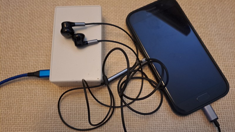
The “keyboard” starts off in a browser running on a standard smartphone. A user can input text into the browser, which then gets converted into a series of audible audio pulses that can be sent to the keyboard. The keyboard itself listens to those pulses, decodes them, and then sends the text through to the computer as a standard USB device thanks to an Arduino Micro at the center. Arduino Micros are excellent choices for keyboard controllers because they have a built-in USB chip.
The protocol used here is designed and built by [nicolas.ma] as well. The words allow for variable length, with the device determining message length, and a word-ending scheme that automatically sends the message to memory when it’s detected that the message is finished. There’s also integrity checking and the ability to check on the link’s state. From hardware to software it’s an impressive build, and for anyone wondering what this might be used for [nicolas.ma] has already built a password manager from it.
About a month ago, [Greenhill Forge] built a few solar panels to collect energy from the sun. Unlike solar photovoltaics, which turn sunlight directly into electricity, these were designed to gather solar thermal energy with air. These types of panels can gather a tremendous amount of energy for a very low cost, and although the first video only went into the theory of their operation, his latest video actually shows us how to use that energy in a practical way.
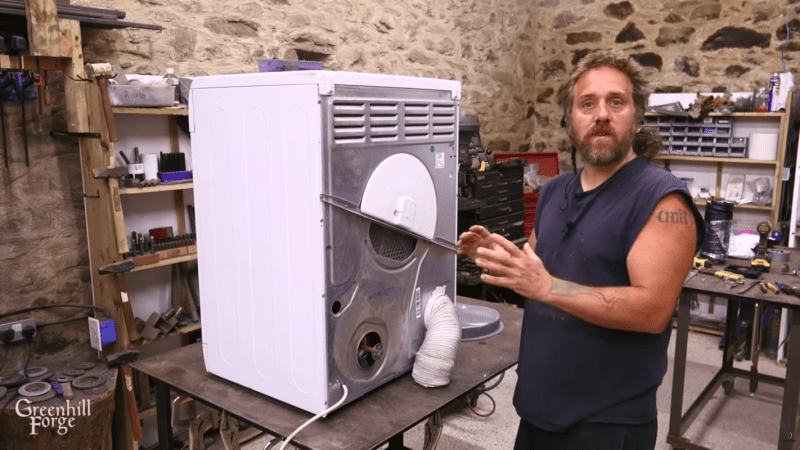
The video starts by building a new solar panel, using upgraded materials and building methods compared to the previous versions which should improve the efficiency. There’s some data analysis of the performance, but at the end of the video [Greenhill Forge] actually hooks one of these up to a clothes dryer to explore its real-world efficacy. This process involves disconnecting the electric heater, removing one of the blower fans, and building a new flange to accept the heated air from the solar panel. A microcontroller keeps an eye on the incoming air temperature and controls a fan to try to hit the target temperature.
After an hour of drying, the test clothing was completely dry, with the only electricity used to turn the drum in the dryer. This is more than an order of magnitude of reduction in the power needed to dry clothes, which is fairly impressive. [Greenhill Forge] also notes that systems like these could augment off-grid systems not only for clothes drying but for home heating, greenhouse heating, or drying out various crops and that they could reduce strain on an electrical system that otherwise relies on resistive heating methods. There are many ways of building these panels, so be sure to check out his first video for ideas.