This project builds a basic electronic door lock with the Arduino UNO R4 WiFi. A touch sensor detects contact, a relay controls a solenoid lock, and an OLED display shows the system status. The principle is simple: touch the sensor, the door unlocks for 5 seconds, then locks itself again. It is a starting point for customizable smart locking systems.
The central board is the Arduino UNO R4 WiFi, which manages the whole flow. The touch sensor sends a signal to the board, which activates the relay to power the lock. The 128×64 pixel OLED display shows the startup, locked, and unlocked screens. The system uses a relay module to separate the control circuit from the power circuit, so the solenoid lock operates safely.
The circuit and components of the lock
Assembly requires few components: the Arduino board, the touch sensor, the OLED display, the relay module, and a solenoid lock. Everything connects on a breadboard with jumper wires. The relay is essential because the lock runs at 12 VDC, while the Arduino operates at 5 V. Without the relay, the lock’s current would damage the board.
The OLED display connects via I2C, using the SSD1306 and Adafruit_GFX libraries. The 128×64 pixel resolution is enough to show the system status with clear characters. The touch sensor connects to a digital pin: when it detects a touch, it sends a high signal to the Arduino. The response is immediate, and the relay trips right away.
The firmware and unlock time
The code is written in the Arduino IDE and uses the SSD1306, Adafruit_GFX, and Adafruit_SSD1306 libraries. The sketch reads the touch sensor state and, when it detects a touch, activates the relay. The display shows the unlock screen for 5 seconds, then the system locks the door again. The unlock time is fixed at 5 seconds, but it can be changed in the code.
The operation is cyclic: startup, waiting, unlock, relock. The OLED display updates the status in real time, so you always know whether the door is locked or unlocked. The project demonstrates the principle of a basic electronic lock, and the maker’s website collects the details for replicating it. It is a simple but complete system.
For assembly you also need a universal acrylic support to keep the Arduino and breadboard tidy. 15 cm male-to-female jumper wires help connect the modules without soldering. The project can be expanded with a numeric keypad, an RFID reader, or a Wi-Fi module for remote control.
In short, this project is an excellent base for anyone who wants to understand how an electronic lock works. The components are few, the code is essential, and the result is functional. With the Arduino UNO R4 WiFi you also have the option to add connectivity in the future, turning the prototype into a real smart lock.
We bring the connections of the STEMMA QT/Qwiic connector available on the Arduino UNO R4 WiFi to the outside, using a board that can host I²C-Bus devices and can be daisy-chained with others of the same type.
Among the new features introduced by the Arduino UNO R4, the WiFi version stands out with a small interface connector called STEMMA QT/Qwiic. For form-factor compatibility reasons, this connection did not find a place in the traditional headers compatible with UNO boards, but it is located on the left side of the ICSP.
The connector makes an I²C-Bus accessible according to the pinout shown in Fig. 1, which can be used to manage external devices such as displays, sensors, etc., as long as they support I²C communication.
Fig. 1 Position of the STEMMA QT/Qwiic connector on the Arduino R4 WiFi board.
The SCL and SDA lines, unlike what happens in previous Arduino boards based on Atmel processors (where they were shared with pins A4 and A5 of the standard Arduino header), are connected to a second (secondary) I²C bus. In fact, the Renesas chip used in the R4 makes two distinct I²C buses available. The second one must be managed, however, by calling the specific object Wire1, as will be explained later in this article. The connection was introduced in the Arduino R4 (only in the WiFi version) to quickly connect Sparkfun standard breakout boards to it, since the connector used, a 4-pin single-in-line PCB connector, is the one adopted by Sparkfun boards. Qwiic is an ecosystem of breakout modules and development boards equipped with a so-called Qwiic connector, and it combines the flexibility of I²C with the ease of use of ready-made compatible cables available on the market, making it simple to manage a chain of I²C-Bus devices through a single cable. In practice, this means that wiring Qwiic devices is as simple as connecting them in series, and that’s it. To facilitate the connection and provide physical support for the breakout boards, instead of leaving them “flying,” we thought of designing and proposing a small adapter board that has two connectors compatible with the STEMMA QT/Qwiic standard, creating a pass-through connection that allows interfacing devices on the board itself, but also using the I²C bus to connect other devices. The I²C-Bus connections are distributed on our board in rows of pads where you can insert strips to connect and mechanically support breakout boards. Everything will be clearer by analyzing the project’s electrical schematic, which you can find on this page.
Electrical schematic
Electrical schematic of the adapter board.
As you can see, it is something very simple, which in fact has no electronics but simply creates a series of electrical interconnections, making a pass-through I²C-Bus connection between input and output through the two 4-pin Sparkfun-type connectors, and which has four rows of four pads at 2.54 mm pitch, ready for soldering female strips or pin strips for sensors and various devices. Note that the layout on the printed circuit board provides that the rows of pads have contacts arranged differently from one side to the opposite one: we wanted this to allow mounting boards and especially displays (since the problem occurs, for example, with small OLEDs) that have a different arrangement of Vcc and GND, as well as SDA and SCL. Through the STEMMA QT/Qwiic connector, the power needed for the breakout boards to operate is taken from the Arduino UNO R4 board, thus achieving independent operation of the devices connected to Arduino. As you can see, the circuit is essential and basically only serves to carry connections. The nice thing is that having two JST connectors makes it possible to daisy-chain numerous I²C-Bus interface devices on multiple boards, since the one connected to the Arduino R4 can in turn be connected to a second board, the latter to a third, and so on, to host more elements. For the interconnection between the Arduino R4 and our board, and between multiple adapter boards, you can use a pre-wired cable with a 4-pin JST connector at each end, 1 mm pitch, available at Futura Elettronica. The adapter board we propose here can also be purchased ready-made from [Futura Elettronica](www.futurashop.it) with product code FT1732M.
Construction and use
Photo of the adapter board.
The small adapter board described here can be easily prepared by photoengraving once you have the two copper-side traces, however, given its really low cost, it is possible and convenient to buy it ready-made. To explain how to use it, we propose a basic application that involves acquiring information from a breakout board for barometric pressure and ambient temperature sensors, then displaying it on a small 0.96″ monochrome OLED display based on the SSD1306 controller; clearly, we are referring to two devices equipped with an I²C-Bus interface. The Arduino R4 WiFi connector to use is the one detailed in Fig. 2. To use a Bosch BME280 sensor on a breakout board with the Arduino R4 and the STEMMA standard, you must mount the small breakout board using the appropriate pin strips and following the intended orientation (Fig. 3 can help you, where you can also see in which position to mount it); be careful that if you do not respect the indicated position and orientation, the small board can be irreparably damaged.
Fig. 2 The JST connector for the Qwiic STEMMA connection to be used to connect our board.
Fig. 3 The adapter with an I²C BME280 sensor on a breakout board.
This is because, as mentioned, the rows of I²C-Bus pads inside the printed circuit board are arranged differently depending on which side they are on, to allow mounting all breakout boards available on the market, equipped with 2.54 mm pitch strip connections. On a second FT1732M adapter board, you must mount the small OLED display, which is a standard type and, more precisely, the one sold by Futura Elettronica with the code OLEDGVSCSD; the device must be applied as shown in Fig. 4 after soldering a 4-pin pin-strip to it and using the row of pads whose contacts are arranged as follows: GND, VCC, SCL, SDA.
Fig. 4 The STEMMA QT/Qwiic adapter with the 0.96-inch display module attached.
To implement communication with the BME280 breakout, you must first load the Adafruit_BME280 library into the Arduino IDE; to do this, open the IDE, go to the Sketch menu, and issue the Include Library > Manage Libraries… command. At this point, search for “Adafruit BME280” in the search bar and install the corresponding library. Installation can also be done from a .zip file containing the library, using the appropriate menu command. Then, from the File menu, you can issue the Examples command and load the “BME280_I2C” example; once the sketch is displayed, load it onto the board (the IDE must already have the UNO R4 WiFi among the boards available in the Tools > Board… submenu) and run it, opening the Serial Monitor to view the pressure and temperature data read by the sensor. Note that the Arduino UNO R4 WiFi has two I²C buses and that the Qwiic connector is connected to the secondary one, so you must use Wire1. In most cases, you will be able to select the Wire1 object during library initialization with this code snippet:
Wire1.begin();
libraryName.begin( Wire1 );
Our test sketch
To test the adapter board and the STEMMA Qwiic connection, we wrote for you the simple sketch proposed in Listing 1, which, in association with the breakout board based on BME280 and the OLED display, implements an essential weather station capable of displaying atmospheric pressure and ambient temperature.
To work, the sketch includes the Wire.h, Adafruit Sensor.h, BME280.h, GFX.h, and SSD1306.h libraries, as well as ArduinoGraphics.h and Arduino_LED_Matrix.h to manage the display; in particular, SSD1306.h handles the controller integrated into the OLED display module. In the Setup, the Serial Monitor is initialized for communication at 115200 baud, and then commands are issued to use Wire1, with the instructions:
that will be used to make the Arduino UNO R4 communicate with the display and the BPM280 sensor through the Qwiic / STEMMA interface. Once this is done, the I²C-Bus OLED display and the sensor are initialized, then you start acquiring samples of the quantities detected by the latter, sending the result to the display at the corresponding I²C-Bus address. These two operations are repeated in a loop, with a delay time of 20 ms. Note that using the I²C-Bus implies defining the address of the two peripherals in the firmware; in this regard, it should be said that the BME280 breakout typically has address 0x76, which is the default in our sketch; if the query fails and no data appears on the display, it is advisable to change the I²C address in the following line of code:
uint8_t BME_ADDR = 0x76;
replacing 0x76 with 0x77, because breakouts with this preset address also exist. As for the OLED display used in this example, it has an I²C-Bus address of 0x3C, which is fixed and does not vary from manufacturer to manufacturer, because it is defined in the controller chip.
Conclusions
Well, with this we have finished and we leave you to your practical experiments with the Arduino UNO R4 and its Qwiic connection. The application proposed here is one of the many examples of use and employs one board for each I²C-Bus device; however, each one can host, depending on size, multiple breakouts, and remember that the STEMMA/Qwiic connector also supports more than two adapter boards, depending on the current that can be supplied to the bus.
Now and again you may find yourself needing to use more than one device with the same I2C bus address with your Arduino.
Such as four OLEDs for a large display – or seven temperature sensors that are wired across a chicken hatchling coop.
These types of problems can be solved with the TCA9548A 1-to-8 I2C Multiplexer Breakout, and in this guide we’ll run through the how to make it happen with some example devices.
Getting Started
First, consider the TCA9548A itself. It is the gateway between your Arduino and eight separate I2C buses. You have a single bus on one side, connected to your Arduino.
On the other side of the TCA9548A, you have eight I2C buses, and only one of these can be connected to the Arduino at a time. For example (from the data sheet):
The TCA9548 can operate on voltages between 1.8 and 5V DC… and operate with devices that have operating voltages between 1.8 and 5V DC. This is very convenient, as (for example) you can use devices made for 3.3V operation with 5V Arduinos, or vice versa. Awesome. So let’s get started.
The breakout board includes inline header pins, which are not soldered to the board. So you need to do that. An easy way to line up the pins properly is to drop them into a solderless breadboard, as such:
Then after a moment or two of soldering, you’re ready to use:
Next, insert your module into a solderless breadboard and wire it up as shown:
We are using the red and blue vertical strips on the breadboard as 5V and GND respectively. Finally, we connect the 5V and GND from the Arduino to the solderless breadboard, and A4/A5 to SDA/SCL respectively on the breakout board:
The electrical connections are as follows (Module — Arduino):
Vin to 5V
GND to GND
A0 to GND
A1 to GND
A2 to GND
SDA to A4
SCL to A5
Next, we consider the I2C bus address for the TCA9548A. Using the wiring setup shown above, the address is set to 0x70. You only need to change this if one of your other devices also has an address of 0x70, as shown in the next step.
Changing the I2C address of the TCA9548A
The bus address of the TCA9548A is changed using the connections to the A0, A1 and A2 pins. By default in the tutorial we use 0x70, by wiring A0~A2 to GND (known as LOW). Using the table below, you can reconfigure to an address between 0x70 and 0x77 by matching the inputs to HIGH (5V) or LOW (GND):
Testing
Before we get too excited, now is a good time to test our wiring to ensure the Arduino can communicate with the TCA9548A. We’ll do this by running an I2C scanner sketch, which returns the bus address of a connected device.
Copy and paste this sketch into your Arduino IDE and upload it to your board.
This file contains hidden or bidirectional Unicode text that may be interpreted or compiled differently than what appears below. To review, open the file in an editor that reveals hidden Unicode characters.
Learn more about bidirectional Unicode characters
Then, open the serial monitor and set the data rate to 115200. You should be presented with something like the following:
As you can see, our scanner returned an address of 0x70, which matches the wiring described in the bus address table mentioned earlier. If you did not find success, unplug the Arduino from the computer and double-check your wiring – then try again.
Controlling the bus selector
Using the TCA9548A is your sketch is not complex at all, it only requires one step before using your I2C device as normal. That extra step is to instruct the TCA9548A to use one of the eight buses that it controls.
To do this, we send a byte of data to the TCA9548A’s bus register which represents which of the eight buses we want to use. Each bit of the byte is used to turn the bus on or off, with the MSB (most significant bit) for bus 7, and the LSB (least significant bit) for bus 0.
For example, if you sent:
0b00000001 (in binary) or 0 in decimal
… this would activate bus zero.
Or if you sent:
0b00010000 (in binary)
… this would activate bus five.
Once you select a bus, the TCA9548A channels all data in and out of the bus to the Arduino on the selected bus. You only need to send the bus selection data when you want to change buses. We’ll demonstrate that later.
So to make life easier, we can use a little function to easily select the required bus:
void TCA9548A(uint8_t bus)
{
  Wire.beginTransmission(0x70);  // TCA9548A address is 0x70
  Wire.write(1 << bus);          // send byte to select bus
  Wire.endTransmission();
}
This function accepts a bus number and places a “1” in the TCA9548A’s bus register matching our requirements. Then, you simply slip this function right before needing to access a device on a particular I2C bus. For example, a device on bus 0:
TCA9548A(0);
… or a device on bus 6:
TCA9548A(6);
A quick note about pull-up resistors
You still need to use pull-up resistors on the eight I2C buses eminating from the TCA9548A. If you’re using an assembled module, such as our example devices – they will have the resistors – so don’t panic.
If not, check the data sheets for your devices to determine the appropriate pull-up resistors value. If this information isn’t available, try 10k0 resistors.
It is has four connections, which are wired as follows (OLED — TCA9548A/Arduino):
GND to GND
Vcc to Arduino 3.3V
CL to TCA9548A SC0 (bus #0, clock pin)
DA to TCA9548A SD1 (bus #0, data pin)
The OLED runs from 3.3V, so that’s why we’re powering it directly from the Arduino’s 3.3V pin.
Now, copy and upload this sketch to your Arduino:
This file contains hidden or bidirectional Unicode text that may be interpreted or compiled differently than what appears below. To review, open the file in an editor that reveals hidden Unicode characters.
Learn more about bidirectional Unicode characters
After a moment the OLED will display some numbers counting down in various amounts (video):
So how did that work? We inserted our bus selection function at line 5 of the sketch, then called the function in at line 22 to tell the TCA9548A that we wanted to use I2C bus zero. Then the rest of the sketch used the OLED as normal.
Controlling two devices
Let’s add another device, a BMP180 barometric pressure sensor module. We’ll connect this to I2C bus number seven on the TCA5948A. There are four connections, which are wired as follows (BMP180 — TCA9548A/Arduino):
GND to GND
Vcc to Arduino 3.3V
CL to TCA9548A SC0 (bus #7, clock pin)
DA to TCA9548A SD1 (bus #7, data pin)
Now, copy and upload this sketch to the Arduino, and after a moment the OLED will display the ambient temperature from the BMP180 in whole degrees Celsius.
This file contains hidden or bidirectional Unicode text that may be interpreted or compiled differently than what appears below. To review, open the file in an editor that reveals hidden Unicode characters.
Learn more about bidirectional Unicode characters
This is demonstrated in the following video (finger is placed on the BMP180 for force a rise in temperature)(video):
So how did that work? We set up the libraries and required code for the OLED, BMP180 and TCA5948A as usual.
We need to intialise the BMP180, so this is done at line 24 – where we select the I2C bus 7 before initiating the BMP180.
The the sketch operates. On line 34 we again request I2C bus 7 from the TCA9548A, then get the temperature from the BMP180.
On line 38 we request I2C bus 0 from the TCA9548A, and then display the temperature on the OLED. Then repeat.
A quick note about the reset pin
More advanced users will be happy to know they can reset the TCA9548A status, to recover from a bus-fault condition. To do this, simply drop the RESET pin LOW (that is, connect it to GND).
Where to from here?
You can now understand through our worked example how easy it is to use the TCA9548A and access eight secondary I2C buses through the one bus from your Arduino. Don’t forget that the TCA9548A also does double-duty as a level converter, thereby increasing its value to you.
I hope you enjoyed reading about these useful TCA9548A boards. To keep up to date with new posts at tronixstuff.com, please subscribe to the mailing list in the box on the right, or follow us on x – @tronixstuff.
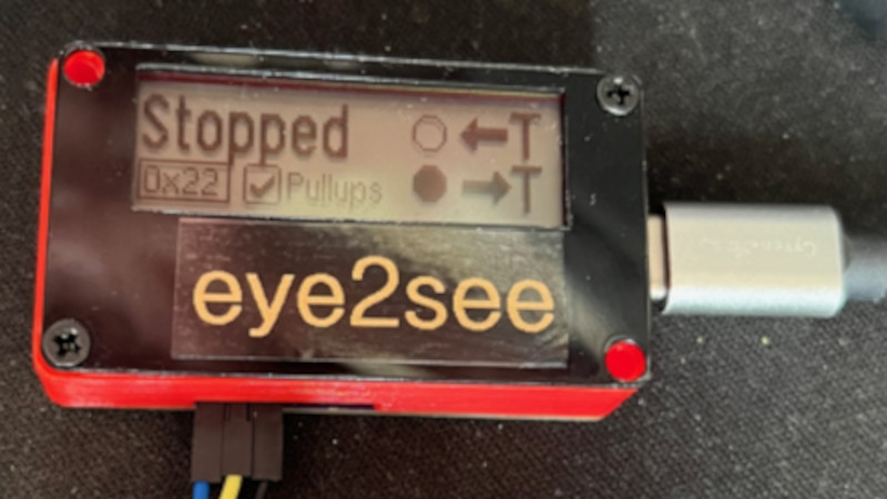
For as popular as the Arduino platform is, it’s not without its problems. Among those is the fact that most practical debugging is often done by placing various print statements throughout the code and watching for them in the serial monitor. There’s not really a great way of placing breakpoints or stepping through code, either. But this project, known as eye2see, hopes to change that by using the i2c bus found in most Arduinos to provide a more robust set of debugging tools.
The eye2see software is set up to run on an Arduino or other compatible microcontroller, called the “probe”, which is connected to the i2c bus on another Arduino whose code needs to be debugged. Code running on this Arduino, which is part of the eye2see library, allows it to send debugging information to the eye2see probe. With a screen, the probe can act as a much more powerful debugger than would otherwise typically be available, being able to keep track of variables in the main program, setting up breakpoints, and outputting various messages on its screen.
The tool is not without its downsides, though. The library that needs to run on the host Arduino slows down the original program significantly. But for more complex programs, the tradeoff with powerful debugging tools may be worth it until these pieces of code can be removed and the program allowed to run unencumbered. If you’d like to skip needing to use a second Arduino, we’ve seen some other tools available for debugging Arduino code that can run straight from a connected PC instead.
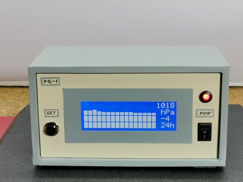
Computers and digital sensors have allowed for the collection and aggregation of data barely possible to imagine to anyone in the instrumentation scene even sixty years ago. Before that, things like weather stations, seismometers, level sensors, and basically any other way of gathering real data about the world would have been performed with an analog device recording the information on some sort of spool of paper. This was much more tedious but the one thing going for these types of devices was their aesthetic. [mircemk] is back to bring some of that design inspiration to a digital barometric display.
The barometer is based around an Arduino Arduino Nano and a relatively large I2C display to display the captured data. It also uses a BME 280 pressure sensor board, but the technical details of this project are not the focal point here. Instead, [mircemk] has put his effort in recreating the old analog barographs, which display barometric data on a spool of paper over time, on the I2C display. As the device measures atmospheric pressure, it adds a bar to the graph, displaying the data over time much as the old analog device would have.
We’ve discussed plenty of times around here that old analog meters and instrumentation like this recreation of a VU meter are an excellent way of getting a more antique aesthetic than is typically offered by digital replacements. Adding in a little bit of style to a project like this can go a long way, or you can simply restore the original antique instead.
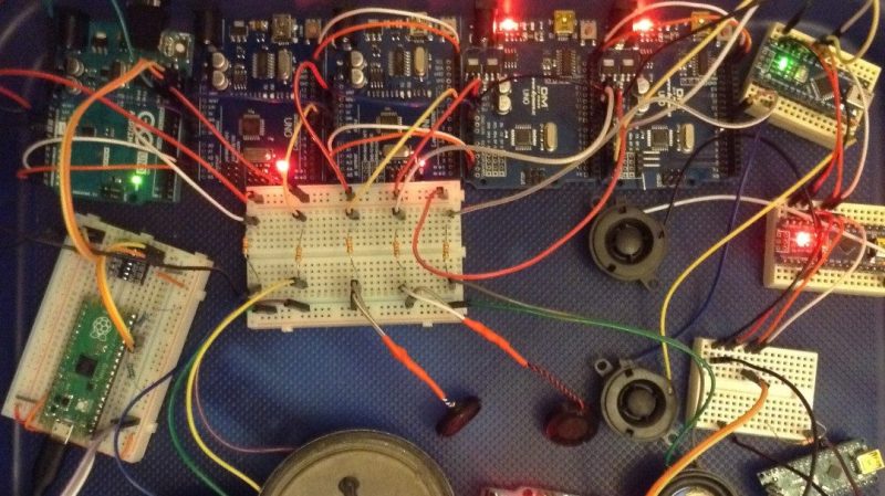
The Musical Instrument Digital Interface has a great acronym that is both nice to say and cleanly descriptive. The standard for talking to musical instruments relies on a serial signal at 31250 bps, which makes it easy to transmit using any old microcontroller UART with a settable baud rate. However, [Kevin] has dived into explore the utility of sending MIDI signals over I2C instead.
With a bit of hacking at the Arduino MIDI library, [Kevin] was able to get the microcontroller outputting MIDI data over the I2C interface, and developed a useful generic I2C MIDI transport for the platform. His first tests involved using this technique in concert with Gravity dual UART modules. After he successfully got one running, [Kevin] realised that four could be hooked up to a single Arduino, giving it 8 serial UARTS, or, in another way of thinking, 8 MIDI outputs.
At its greatest level of development, [Kevin] shows off his I2C MIDI chops by getting a single Raspberry Pi Pico delivering MIDI signals to 8 Arduinos, all over I2C. All the Arduinos are daisy-chained with their 5V and I2C lines wired together, and the system basically swaps out traditional MIDI channels for I2C addresses instead.
There’s not a whole lot of obvious killer applications for this, but if you want to send MIDI data to a bunch of microcontrollers, you might find it easier daisy-chaining I2C rather than hopping around with a serial line in the classic MIDI-IN/MIDI-THRU fashion.
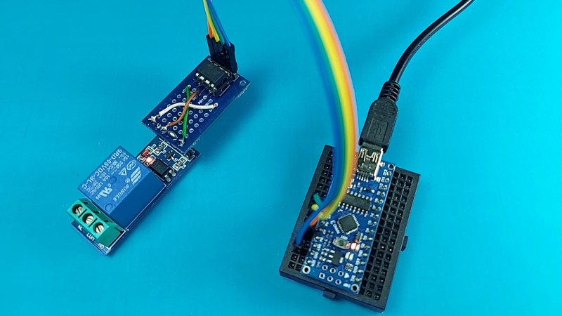
The Arudino is a powerful platform for interfacing with the real world, but it isn’t without limits. One of those hard limits, even for the Arduino MEGA, is a finite number of pins that the microcontroller can use to interface with the real world. If you’re looking to extend the platform’s reach in one of your own projects, though, there are a couple of options available. This project from [Bill] shows us one of those options by using the ATtiny85 to offload some of an Arduino’s tasks using I2C.
I2C has been around since the early 80s as a way for microcontrollers to communicate with each other using a minimum of hardware. All that is needed is to connect the I2C pins of the microcontrollers and provide each with power. This project uses an Arduino as the controller and an arbitrary number of smaller ATtiny85 microcontrollers as targets. Communicating with the smaller device allows the Arduino to focus on more processor-intensive tasks while giving the simpler tasks to the ATtiny. It also greatly simplifies wiring for projects that may be distributed across a distance. [Bill] also standardizes the build with a custom dev board for the ATtiny that can also double as a shield for the Arduino, allowing him to easily expand and modify his projects without too much extra soldering.
Using I2C might not be the most novel of innovations, but making it easy to use is certainly a valuable tool to add to the toolbox when limited on GPIO or by other physical constraints. To that end, [Bill] also includes code for an example project that simplifies the setup of one of these devices on the software end as well. If you’re looking for some examples for what to do with I2C, take a look at this thermometer that communicates with I2C or this project which uses multiple sensors daisy-chained together.
Controlling your computer with a wave of the hand seems like something from science fiction, and for good reason. From Minority Report to Iron Man, we’ve seen plenty of famous actors controlling their high-tech computer systems by wildly gesticulating in the air. Meanwhile, we’re all stuck using keyboards and mice like a bunch of chumps.
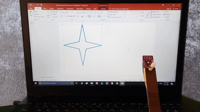
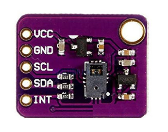
But it doesn’t have to be that way. As [Norbert Zare] demonstrates in his latest project, you can actually achieve some fairly impressive gesture control on your computer using a $10 USD PAJ7620U2 sensor. Well not just the sensor, of course. You need some way to convert the output from the I2C-enabled sensor into something your computer will understand, which is where the microcontroller comes in.
Looking through the provided source code, you can see just how easy it is to talk to the PAJ7620U2. With nothing more exotic than a switch case statement, [Norbert] is able to pick up on the gesture flags coming from the sensor. From there, it’s just a matter of using the Arduino Keyboard library to fire off the appropriate keycodes. If you’re looking to recreate this we’d go with a microcontroller that supports native USB, but technically this could be done on pretty much any Arduino. In fact, in this case he’s actually using the ATtiny85-based Digispark.
This actually isn’t the first time we’ve seen somebody use a similar sensor to pull off low-cost gesture control, but so far, none of these projects have really taken off. It seems like it works well enough in the video after the break, but looks can be deceiving. Have any Hackaday readers actually tried to use one of these modules for their day-to-day futuristic computing?
In an age of streaming media it’s easy to forget the audio CD, but they still remain as a physical format from the days when the “Play” button was not yet the “Pay” button. A CD player may no longer be the prized possession it once was, but it’s still possible to dabble in the world of 120 mm polycarbonate discs if you have a fancy for it. It’s something [Daniel1111] has done with his Arduino CD player, which uses the little microcontroller board to control a CD-ROM drive via its IDE bus.
The project draws heavily from the work of previous experimenters, notably ATAPIDUINO, but it extends them by taking its audio from the drive’s S/PDIF output. A port expander drives the IDE interface, while a Cirrus Logic WM8805 S/PDIF transceiver handles the digital audio and converts it to an I2S stream. That in turn is fed to a Texas Instruments PCM5102 DAC, which provides a line-level audio output. All the code and schematic can be found in a GitHub repository.
While the SSD1306 OLED has somewhat become the go-to display for up-to-date projects, the good old character displays with their Hitachi HD44780 controller don’t seem to be disappearing just yet either. And why would they, especially if you want to show just text, having a built-in font has certainly its perk compared to worrying about integrating your own characters — which you can still do on top as well. Or perhaps you can combine both worlds, which is what [oldmaninSC] did with his digital clock that takes an entire 16×2 LCD to show each single digit.
The whole clock uses 16 individual, upright rotated 16×2 LCDs that are arranged in two rows of eight LCDs each, turning the entire construct sort of into a giant 8×2 display itself. For some additional information such as the date, there’s also a smaller font available that uses only half the height, allowing up to four total rows of information. To communicate with each LCD via I2C, two TCA9548A I2C multiplexers are connected to an Arduino, along with an RTC to keep track of the time and date itself.
As the TCA9548A has three pins dedicated to define its own address, the entire clock could be scaled up to a total of 64 LCDs — so how about a 16×4 display made out of 16×4 displays? Sure, adding smooth scrolling might become a bit tricky at some point, but imagine playing Tetris on that one!