Posts with «breadboard» label

Build an 8-Key Piano on a Breadboard with Arduino

An 8-key piano on a breadboard with an Arduino Uno R3, eight 6×6 mm tactile buttons and a passive piezo buzzer. Each key you press plays a note of the C major scale, from C4 at 262 Hz up to C5 at 523 Hz. That is enough to play tunes like Twinkle Twinkle Little Star. No shield, no external library and no soldering are needed: just a breadboard, jumpers and a USB cable.

Assembly is the quickest part. The tactile buttons go into the breadboard straddling the centre channel, one next to the other. Each button has one side connected to an Arduino digital pin and the other side to GND. The passive buzzer has its positive leg on pin D10 and its negative leg on GND. A jumper connects the breadboard’s GND rail to the board’s ground.

The keys occupy pins D2 to D9, eight consecutive digital pins. The Arduino Uno has 14 digital pins (D0-D13) and 6 analog pins usable as digital inputs, so there is plenty of room to add keys in a later version. For the keys, the catalogue has a 6×6 mm PCB mini pushbutton, the same format used in the project.

INPUT_PULLUP and the tone() function in the firmware

The code uses no library: it relies on the tone() function built into the Arduino IDE. Each button is connected between a pin and GND, so the firmware enables the internal pull-up resistor with INPUT_PULLUP. As a result the pin reads HIGH when the key is at rest and LOW when it is pressed. The code scans the eight pins, stores the first key pressed and calls tone() with the associated frequency.

The comparison if (pressedKey != lastKey) makes tone() fire only once per press, instead of repeating the call on every pass of the loop. When no key is pressed, the code calls noTone() and the sound stops. The serial monitor opens at 9600 baud and is used to check which keys are being read during testing.

  • Key 1: C4 at 262 Hz
  • Key 2: D4 at 294 Hz
  • Key 3: E4 at 330 Hz
  • Key 4: F4 at 349 Hz
  • Key 5: G4 at 392 Hz
  • Key 6: A4 at 440 Hz
  • Key 7: B4 at 494 Hz
  • Key 8: C5 at 523 Hz

The piano is monophonic, and that is a limitation of the tone() function: it generates only one frequency at a time. So if you press two keys together, the one with the lower number wins, that is, the first one the loop encounters. Anyone who wants real chords has to change approach, for example generating the waveforms by hand with a timer.

Passive buzzer, current draw and an alternative speaker

The passive piezo buzzer works from 3.3V to 5V and draws less than 30 mA, so you can drive it straight from an Arduino pin without a transistor. Its best output is around 2-4 kHz, while the notes of this piano run from 262 Hz to 523 Hz. The sound comes out, but don’t expect concert volume: to raise the sound pressure, a speaker is a better bet.

Instead of the buzzer you can use an 8 ohm speaker with a 100 ohm resistor in series. The resistor limits the current and protects the pin. On top of that, the sound is fuller on the low notes of the scale. The rest of the circuit does not change: positive on D10, negative on GND.

Rebuilding the project takes only a few parts: an Arduino Uno R3, eight 6×6 mm tactile buttons, a passive piezo buzzer, a breadboard, jumpers and a USB cable. The cost is low and so is the difficulty. In fact it is an ideal first project for learning about digital inputs, INPUT_PULLUP and the tone() function, and you can finish it in an evening.

If you want to see the build in action, on the maker’s site you will find the video with the piano played key by key. There you can see how the buzzer behaves on the different notes before soldering or buying anything.

Source: https://www.circuitschools.com/arduino-piano-project-with-8-keys-build-a-simple-piano/

Related products

The post Build an 8-Key Piano on a Breadboard with Arduino appeared first on Open Electronics.

Electronic door lock with Arduino UNO R4 WiFi and touch sensor

This project builds a basic electronic door lock with the Arduino UNO R4 WiFi. A touch sensor detects contact, a relay controls a solenoid lock, and an OLED display shows the system status. The principle is simple: touch the sensor, the door unlocks for 5 seconds, then locks itself again. It is a starting point for customizable smart locking systems.

The central board is the Arduino UNO R4 WiFi, which manages the whole flow. The touch sensor sends a signal to the board, which activates the relay to power the lock. The 128×64 pixel OLED display shows the startup, locked, and unlocked screens. The system uses a relay module to separate the control circuit from the power circuit, so the solenoid lock operates safely.

The circuit and components of the lock

Assembly requires few components: the Arduino board, the touch sensor, the OLED display, the relay module, and a solenoid lock. Everything connects on a breadboard with jumper wires. The relay is essential because the lock runs at 12 VDC, while the Arduino operates at 5 V. Without the relay, the lock’s current would damage the board.

The OLED display connects via I2C, using the SSD1306 and Adafruit_GFX libraries. The 128×64 pixel resolution is enough to show the system status with clear characters. The touch sensor connects to a digital pin: when it detects a touch, it sends a high signal to the Arduino. The response is immediate, and the relay trips right away.

The firmware and unlock time

The code is written in the Arduino IDE and uses the SSD1306, Adafruit_GFX, and Adafruit_SSD1306 libraries. The sketch reads the touch sensor state and, when it detects a touch, activates the relay. The display shows the unlock screen for 5 seconds, then the system locks the door again. The unlock time is fixed at 5 seconds, but it can be changed in the code.

The operation is cyclic: startup, waiting, unlock, relock. The OLED display updates the status in real time, so you always know whether the door is locked or unlocked. The project demonstrates the principle of a basic electronic lock, and the maker’s website collects the details for replicating it. It is a simple but complete system.

For assembly you also need a universal acrylic support to keep the Arduino and breadboard tidy. 15 cm male-to-female jumper wires help connect the modules without soldering. The project can be expanded with a numeric keypad, an RFID reader, or a Wi-Fi module for remote control.

In short, this project is an excellent base for anyone who wants to understand how an electronic lock works. The components are few, the code is essential, and the result is functional. With the Arduino UNO R4 WiFi you also have the option to add connectivity in the future, turning the prototype into a real smart lock.

Source: https://srituhobby.com/how-to-make-a-solenoid-door-lock-system-using-a-touch-sensor/

The post Electronic door lock with Arduino UNO R4 WiFi and touch sensor appeared first on Open Electronics.

At last! A SIL-Duino!

There are some standard components that have been so continuously refined as to have become if not perfect then about as good as they’re going to get. Take the Arduino Uno for instance, and compare it with its ancestor from a decade ago. They are ostensibly the same board and they are compatible with each other, yet the Uno and its modern clones have more processing power, memory and storage, a USB interface rather than serial, and a host of small component changes to make them better and cheaper.

You’d think that just another Arduino clone couldn’t bring much to the table then. And you’d be right in a broad sense, just what is there left to improve?

[Clovis Fritzen] has an idea for an Arduino clone that’s worth a second look. It’s not an amazing hardware mod that’ll set the Arduino world on fire, instead it’s a very simple design feature. He’s created an Arduino that mounts vertically on a single row of pins. Why might you find that attractive, you ask? A SIL vertical Arduino takes up a lot less breadboard space than one of the existing DIL Arduinos. A simple idea, yet one that is very useful if you find yourself running out of breadboard.

[Clovis] took the circuit of an Arduino Uno and simplified it by removing the USB interface, so this board has to be programmed through its ICSP header. And he’s made it a through-hole board for easy construction by those wary of SMD soldering. The resulting board files can all be found on GitHub.

Every now and then along comes a hack so simple, obvious, and useful that it makes you wonder just why you didn’t think of it yourself. Many of us will have used a DIL Arduino and probably found ourselves running out of breadboard space. This board probably won’t change the world, but it could at least make life easier in a small way for some of us who tinker with microcontrollers.

This is just the latest of many Arduino clones to find its way onto these pages. In 2013 we asked why the world needed more when featuring one made as a PCB design exercise. There’s even a Hackaday version called the HaDuino developed by [Brian Benchoff]. But while it’s true that Yet Another Vanilla Arduino Clone brings nothing to the table, that should not preclude people from taking the Arduino and hacking it. Every once in a while something useful like this project will come from it, and that can only be a benefit to our community.


Filed under: Arduino Hacks
Hack a Day 05 Mar 12:01

When Worlds Collide: 68008 Bootstrapped by an Arduino Uno

[Peter Bjornx] brings classic microprocessors and modern microcontrollers together with his Arduino bootstrapped 68008 computer. The Motorola 68008 is the 8-bit external bus version of the well-known 68000 (or 68k) microprocessor. A friend gave [Peter] one of these chips, so he built a simple computer around it.

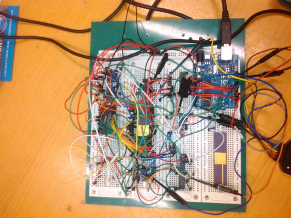
This isn’t one of those clean retrocomputers with every connection carefully planned out and wire wrapped. [Peter's] created a true hack – a working 68k system on a breadboard created with whatever he had on hand at the time. The real gem of this system is the ROM. [Peter] replaced an EPROM chip with an Arduino.

In the not-so-good-old-days, microprocessors (and many microcontrollers) ran from an external ROM chip. This often was a UV-erasable EPROM. Carefully compiled code was burned into the EPROM with a device programmer. If the code wasn’t perfect, the EPROM had to be pulled and placed under a UV lamp for 20 minutes or so to erase it before it was time to try again. EPROM emulators were available, but they were way too expensive for the hobbyist.

Thankfully those days are far behind us now with the advent of EEPROM and then Flash. [Peter] didn’t want to revisit the past either, so he wrote a simple Arduino sketch which allowed it to act as an EPROM emulator, including address logging via the serial port.

The design still caused [Peter] some headaches, though. His major problem was a classic 68k issue, /DTACK timing. /DTACK or Data Transfer Acknowledge is one of several bus control signals used by the 68k. When the 68k performs a read from the data bus, it waits for /DTACK before it transfers data. The Arduino was too slow to release /DTACK in this case, which caused the 68k to think every read was immediately completed. There is a much clearer explanation of the 68k bus cycles on this Big Mess O Wires page. [Peter's] solution was simple – a D flip-flop connected to the address strobe took care of the timing issues.

It took quite a bit of tinkering, but the system eventually worked. Peter was able to run the 68008 from its reset vector into a simple loop using the Arduino. It’s only fitting that the 68k program loaded by the Arduino was an LED blinker, everyone’s favorite hardware Hello World.

Thanks [Robert!]


Filed under: classic hacks, Microcontrollers

Sensing Hot and Cold with Weekend Projects

Combine an Arduino, an ultransonic distance sensor, and some common components to build a classic "hot/cold" project. Once assembled, we'll walk through the software "sketch" loaded onto our Arduino, and experiment with three variations of the "hot/cold" theme, all the while using the same circuit.

Read the full article on MAKE

Freaklabs' FredBoard gives the gift of hackerspace to Mothership HackerMoms

Come this (Black) Friday, it'll officially be the season for gift-giving and general family dysfunction. So, why not warm that tech-tinkering heart while heating up the creative juices of the baby-bound set with a Freaklabs purchase that puts your money to good use? The outfit's got a monster mash FredBoard up for order that splices together an Arduino and breadboard to make your first brush with homegrown modding a relatively painless affair. Oh, and the proceeds are destined for a Mommy-centric hackerspace -- dubbed Mothership HackerMoms -- in San Francisco that does double duty as a day care for little leg-clingers and a lab for their electronics-inclined parents. These ladies-in-programming currently swap house hosting duties, but with the boost from your potential feel-good donations, could snag a proper venue of their own. Feel like getting in the holiday spirit early? Then click on the source below to bring some early cheer to Bay Area baby Mommas.

Freaklabs' FredBoard gives the gift of hackerspace to Mothership HackerMoms originally appeared on Engadget on Mon, 21 Nov 2011 19:04:00 EST. Please see our terms for use of feeds.

Permalink | Email this | Comments