Posts with «general» label
3D-Printed Smart Watch Wins Our Arduino Challenge, Heading to Maker Faire Rome
The Centurion Project: LED Helmet
7 meters of RGB LEDs crammed onto a centurion’s helmet? It makes perfect sense once you see it in action. When you’re a creative developer with a name like Roman, you’re bound to find yourself recreating things from antiquity. Roman Cory found his inevitable foray into ancient Roman culture resulted […]
Wyolum 3rd annual Innovation Grant - 2013
Are you working on a cool project? Do you want to make $2,000? Share it with the world by open sourcing it and you may win the Wyolum Innovation Grant! Now in its 3rd year!
This is the place to submit your project, find out the rules and deadline, and generally learn more about this generous team of innovators!
Eulogy for my Chumby
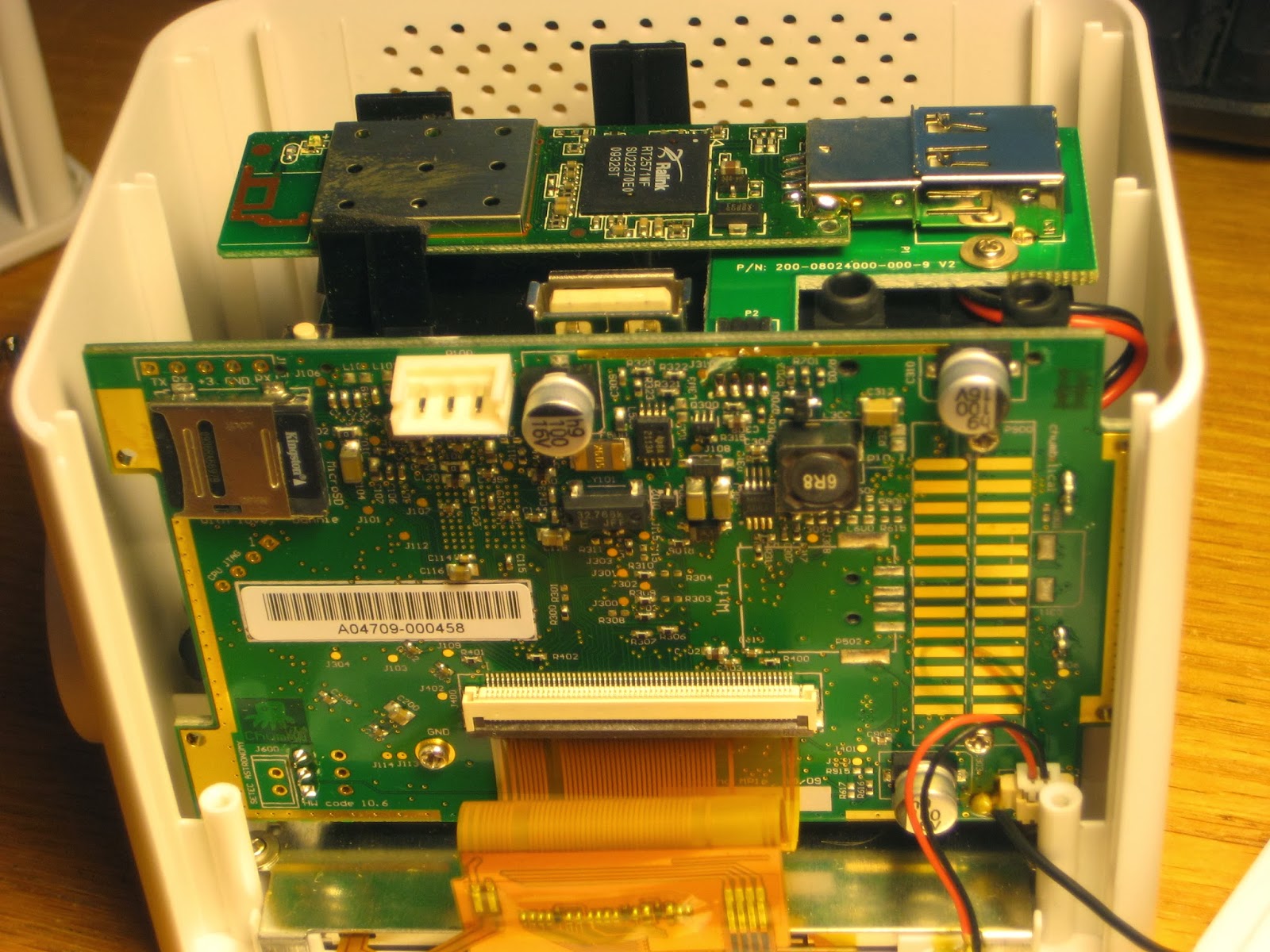
My beloved Chumby One died today. I first thought to be a software glitch, since the booting seemed to take a long time, then it seemed to re-boot itself after a little while. After a few cold resets, the screen started to literally flash, like the flash of a camera, once every 2 or 3 seconds. Not a good sign. I opened it up, for the first time. Beautiful on the inside too. Regretfully, it does not look like something I could repair.
My Chumby served me faithfully and inspired me (I am not kidding) for the last 4 years or so, mainly as a desk clock . It had all the features I wanted in such a device: fairly sized touch screen, good WiFi, great speaker (bass reflex nonetheless), reasonable radio, rotary encoder for volume (or menu scrolling), backup battery, USB socket, internal SD card for the operating system. In the beginning, the OS allowed for various apps to be downloaded and installed (support was cut after the company went bankrupt). The app-installation process was seamless, comparable with today's Google Play, just earlier. The alarm clock app I used was perfect, with snooze, night dimming, always displaying accurate time (acquired from ntp time server). Other apps I installed showed photos from flickr, displayed RSS streams, played mp3s from USB stick; there was even a piano app that used the touch screen capabilities. Chumby was really a much cheaper alternative to a tablet, with a similarly great potential. Compared to a smart phone, Chumby's only missing feature was the GSM/GPRS, which I bet was considered to be added (since it has a microphone too). I also liked its stable shape, simple design and ease of use (great way to re-connect to the WiFi network too).
I never understood why it did not have a greater success.
My Chumby served me faithfully and inspired me (I am not kidding) for the last 4 years or so, mainly as a desk clock . It had all the features I wanted in such a device: fairly sized touch screen, good WiFi, great speaker (bass reflex nonetheless), reasonable radio, rotary encoder for volume (or menu scrolling), backup battery, USB socket, internal SD card for the operating system. In the beginning, the OS allowed for various apps to be downloaded and installed (support was cut after the company went bankrupt). The app-installation process was seamless, comparable with today's Google Play, just earlier. The alarm clock app I used was perfect, with snooze, night dimming, always displaying accurate time (acquired from ntp time server). Other apps I installed showed photos from flickr, displayed RSS streams, played mp3s from USB stick; there was even a piano app that used the touch screen capabilities. Chumby was really a much cheaper alternative to a tablet, with a similarly great potential. Compared to a smart phone, Chumby's only missing feature was the GSM/GPRS, which I bet was considered to be added (since it has a microphone too). I also liked its stable shape, simple design and ease of use (great way to re-connect to the WiFi network too).
I never understood why it did not have a greater success.
Nixie tube clock miscellany
Honestly, one of the reasons behind my latest infatuation with Nixie tube clocks is trying to understand why so many people got so fascinated so quickly and so suddenly with them, although they are not cheap, and although they simply show the time with 4, sometimes 6, digits.
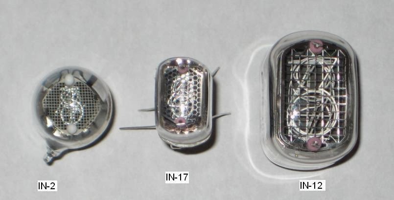
In any case, I'm in the bandwagon now. I designed an Arduinix(TM) variant, based on my previous observations. One of the main differences is that the components sit low on the board, so that a "tube shield" can be plugged on top, similar to akafugu's VFD modular clock. The top "tube shield" can host (at least in theory) up to six IN-2 or four IN-17 (four IN-12 would not fit).
For the "IN-2 tube shield", I downloaded and used the eagle library called "russian-nixies.lbr". Guess what? For the digits to be shown vertically, the IN-2 part needs to be rotated about 45 degrees clockwise. I did not know that until I got my IN-2 tubes. Essentially, the IN-2 tube shield I have is kind-of useless now, unless one uses it for an "artist project" (to quote Pete of PV Electronics, seller of Nixie kits on ebay). That means that the tubes are connected to the PCB with wires, so that they can be placed at artist's fancy. I know Nick is an artist :)
Lesson learned: don't design the PCB until you have all parts in hand.
PS Getting the high voltage (180V) on the new board was just a matter of adjusting the trim pot. No surprises this time.
PS2 Although I did not try it yet, the "Open source Nixie tube shield" sketch should work, with minor modifications, with Arduinix, I reckon.
PS3 Please contact me if you have a need for this PCB or want to buy one.
In any case, I'm in the bandwagon now. I designed an Arduinix(TM) variant, based on my previous observations. One of the main differences is that the components sit low on the board, so that a "tube shield" can be plugged on top, similar to akafugu's VFD modular clock. The top "tube shield" can host (at least in theory) up to six IN-2 or four IN-17 (four IN-12 would not fit).
Lesson learned: don't design the PCB until you have all parts in hand.
PS Getting the high voltage (180V) on the new board was just a matter of adjusting the trim pot. No surprises this time.
PS2 Although I did not try it yet, the "Open source Nixie tube shield" sketch should work, with minor modifications, with Arduinix, I reckon.
PS3 Please contact me if you have a need for this PCB or want to buy one.
Alarm clock app for iPhone
My young friend Rami left his comfortable and safe permanent job with a solid consulting company to start his own business, mainly writing apps for mobile devices. His first app is "Deep Sleep Alarm" for iPhone, available for download in the App Store.
The app is free, with nice graphics and useful functionality, basically making sure you are not "cheating" when waking up :) Please give it a try.

He is currently working on the Android version.
Rami, keep up the great work!
The app is free, with nice graphics and useful functionality, basically making sure you are not "cheating" when waking up :) Please give it a try.

He is currently working on the Android version.
Rami, keep up the great work!
High voltage power sources for tubes (Nixie, VFD, Geiger)
This is a superficial review of the few schematics I encountered while building Nixie clocks, VFD clocks and Geiger counters (no tube amplifier just yet). Although the schematics seemed basic at a glance, they usually ended up being a challenge (that is, they rarely worked right away) for me. That's another reason I am trying to cover them here, so I can use this post as consolidated reference any time I need it.
Tubes require high voltage to work. Some (Vacuum Fluorescent Display) need 40V, others (Nixie) 180-200V, and some others (Geiger) even higher, 400-1000V. The high voltages are generated these days by switching-mode power supplies. Essentially, there is only a handful of popular solutions, and each DIY tube kit picks one of these, based on size, power requirements, cost.
In principle, a switching mode power supply, also known as "boost converter", uses a square wave oscillator ("switch") to create magnetic energy in an inductor, then releasing it as high voltage.
Some scientific explanation (with formulas) can be found here, some practical advice (with schematics and photos) here. Adafruit has a very useful online boost calculator.
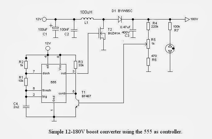
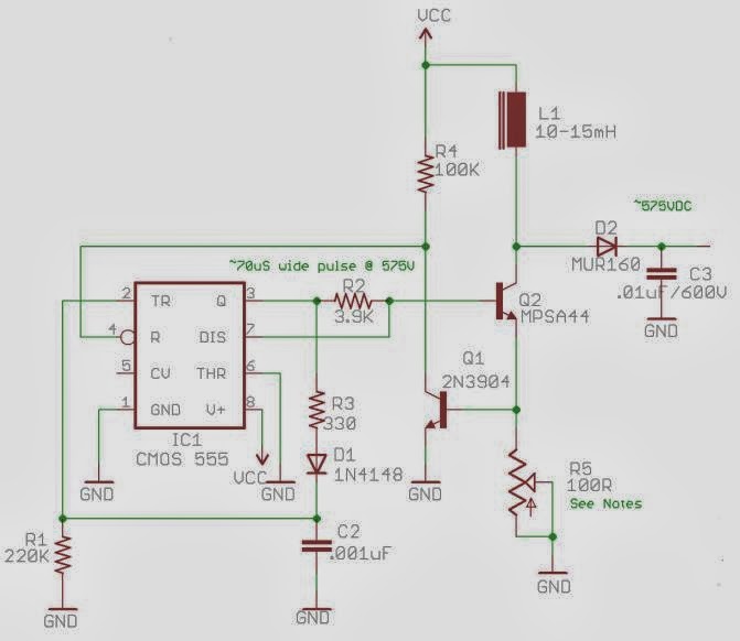
1. One of the most popular solution for the square wave oscillator is by using the ubiquitous 555. This is inexpensive, but requires some tweaking and adjusting (values of resistors and capacitors). The schematic is standard, but there seem to be a few variations.
The one below is from Ronald Dekker.
Frank clock (from Pete's Nixie kits) uses an almost identical schematic, but a different set of values for R2-R3- C4 (used for setting the frequency). In the end, the oscillator frequency is about the same at approx 30kHz, calculated with formula f = 1/0.693/C4/(R3+2R2) (in the schematic below).
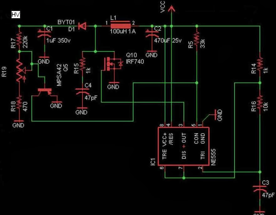
Same 555 is used in Arduinix, but in a different configuration, although still as astable oscillator. This one has an extra HV capacitor (C4) in series with a resistor (R15), whose exact purpose I don't understand. The oscillation frequency is also weird, according to the above formula, with C3 at 47pF, should be 1.5kHz. No wonder this did not work for me.
Another almost identical HV power supply for Nixie tubes is used in the recently-kickstarted "Nixie tube shield" (for which I pledged $15 for the PCB, and yet to receive it).
And finally, 555 is also used to generate the higher voltages required by Geiger tubes, as used by BroHogan (and MightyOhm). The frequency of oscillation is 4.5kHz (f = 1/R1/C2). (I built several Geiger kits from BroHogan and they were all trouble-free.)
2. Other solutions use specialized chips like MAX1771 and MC34063.
Shown below is the high-efficiency boost converter from Nick de Smith (sold by ogiLumen), based on MAX1771.
Akafugu's VFD Version 1 clock uses the same MAX1771, to generate a lower 50V (for VFD tubes).
For MK2, Akafugu switched to using MC34063 chip (schematic not published yet).
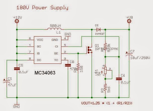
The same chip is also used in their Nixie clock (schematic shown below), to generate 180V. This HV circuit has its own (all SMD) board, which I assembled it myself and worked without a glitch.
3. Yet others use a PWM pin of a microcontroller. This method requires the processor to be connected and programmed in order to generate the high voltage. The solution is cheap (saves an extra chip), smaller in size (again, one less chip), and also seems to be highly efficient.
Below is the HV schematic used by Adafruit's IceTube clock.
Some of the microcontroller-based boost converters have feedback (close loop, with PWM adjusting to the voltage output, if I am not mistaken), as are those from Cogwheel and Satashnik (shown below, respectively).
As with any analog electronics circuit, troubleshooting a HV supply is not easy. A suitable tool would be an oscilloscope, allowing for the measurement and adjustment of the frequency and pulse width. Once these are cleared, the high voltage could be adjusted usually from the trim pot. To modify the voltage range, try different values for the inductor.
Tubes require high voltage to work. Some (Vacuum Fluorescent Display) need 40V, others (Nixie) 180-200V, and some others (Geiger) even higher, 400-1000V. The high voltages are generated these days by switching-mode power supplies. Essentially, there is only a handful of popular solutions, and each DIY tube kit picks one of these, based on size, power requirements, cost.
In principle, a switching mode power supply, also known as "boost converter", uses a square wave oscillator ("switch") to create magnetic energy in an inductor, then releasing it as high voltage.
Some scientific explanation (with formulas) can be found here, some practical advice (with schematics and photos) here. Adafruit has a very useful online boost calculator.
1. One of the most popular solution for the square wave oscillator is by using the ubiquitous 555. This is inexpensive, but requires some tweaking and adjusting (values of resistors and capacitors). The schematic is standard, but there seem to be a few variations.
The one below is from Ronald Dekker.
Frank clock (from Pete's Nixie kits) uses an almost identical schematic, but a different set of values for R2-R3- C4 (used for setting the frequency). In the end, the oscillator frequency is about the same at approx 30kHz, calculated with formula f = 1/0.693/C4/(R3+2R2) (in the schematic below).
Same 555 is used in Arduinix, but in a different configuration, although still as astable oscillator. This one has an extra HV capacitor (C4) in series with a resistor (R15), whose exact purpose I don't understand. The oscillation frequency is also weird, according to the above formula, with C3 at 47pF, should be 1.5kHz. No wonder this did not work for me.
Another almost identical HV power supply for Nixie tubes is used in the recently-kickstarted "Nixie tube shield" (for which I pledged $15 for the PCB, and yet to receive it).
And finally, 555 is also used to generate the higher voltages required by Geiger tubes, as used by BroHogan (and MightyOhm). The frequency of oscillation is 4.5kHz (f = 1/R1/C2). (I built several Geiger kits from BroHogan and they were all trouble-free.)
2. Other solutions use specialized chips like MAX1771 and MC34063.
Shown below is the high-efficiency boost converter from Nick de Smith (sold by ogiLumen), based on MAX1771.
Akafugu's VFD Version 1 clock uses the same MAX1771, to generate a lower 50V (for VFD tubes).
For MK2, Akafugu switched to using MC34063 chip (schematic not published yet).
The same chip is also used in their Nixie clock (schematic shown below), to generate 180V. This HV circuit has its own (all SMD) board, which I assembled it myself and worked without a glitch.
3. Yet others use a PWM pin of a microcontroller. This method requires the processor to be connected and programmed in order to generate the high voltage. The solution is cheap (saves an extra chip), smaller in size (again, one less chip), and also seems to be highly efficient.
Below is the HV schematic used by Adafruit's IceTube clock.
Some of the microcontroller-based boost converters have feedback (close loop, with PWM adjusting to the voltage output, if I am not mistaken), as are those from Cogwheel and Satashnik (shown below, respectively).
As with any analog electronics circuit, troubleshooting a HV supply is not easy. A suitable tool would be an oscilloscope, allowing for the measurement and adjustment of the frequency and pulse width. Once these are cleared, the high voltage could be adjusted usually from the trim pot. To modify the voltage range, try different values for the inductor.
Mechanical Design and Engineering
I was having a conversation with my friend JohnW, a Mechanical Engineer by education and trade, about his latest "small" project. I suggested he should publish and document aspects of his interesting work. But he mentioned he does not have a blog just yet, so I "volunteered" to do it for him right here, as a quick (and hopefully useful) example.
John designed a portable agitator, a device used for mixing low-viscosity liquids or liquids with small-size solids.
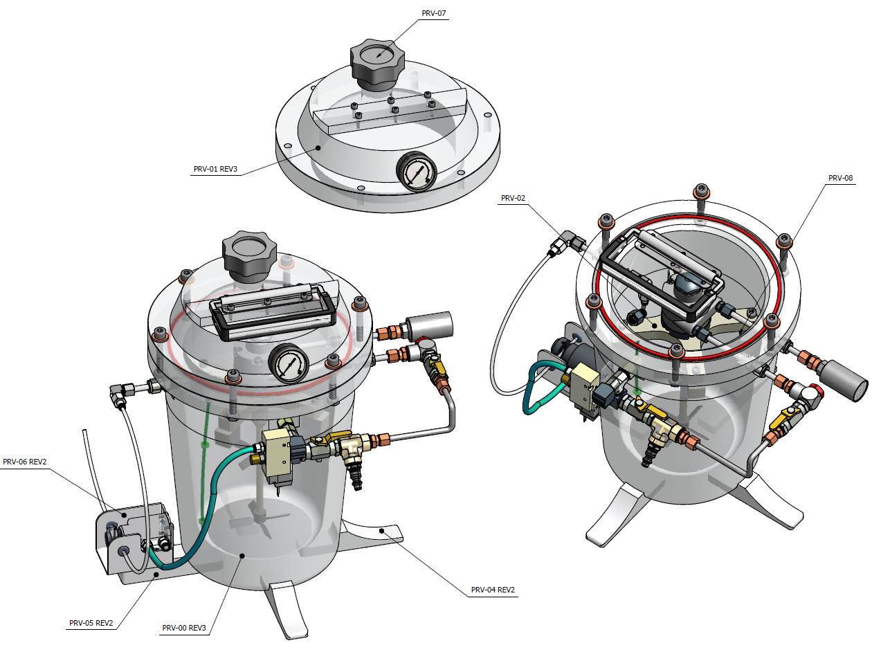
Mixing is performed by a propeller driven by an internal pneumatic system, and not using an electrical motor, as shown in the diagram below.
The whole contraption is made of plastic, calculated for a maximum internal pressure of 80 psi.
The liquids are poured in manually, through PRV-07 (features a screw-in lid). The mixed liquid is released through the pinch-valve PRV-06. The lid PRV-01 can be removed (8 screws) for inside cleaning.
The mixing capacity is 1 gallon, but it can be easily scaled, in both dimensions and power.
This agitator was designed to be safely used in the food, pharmaceutical, chemical industries.
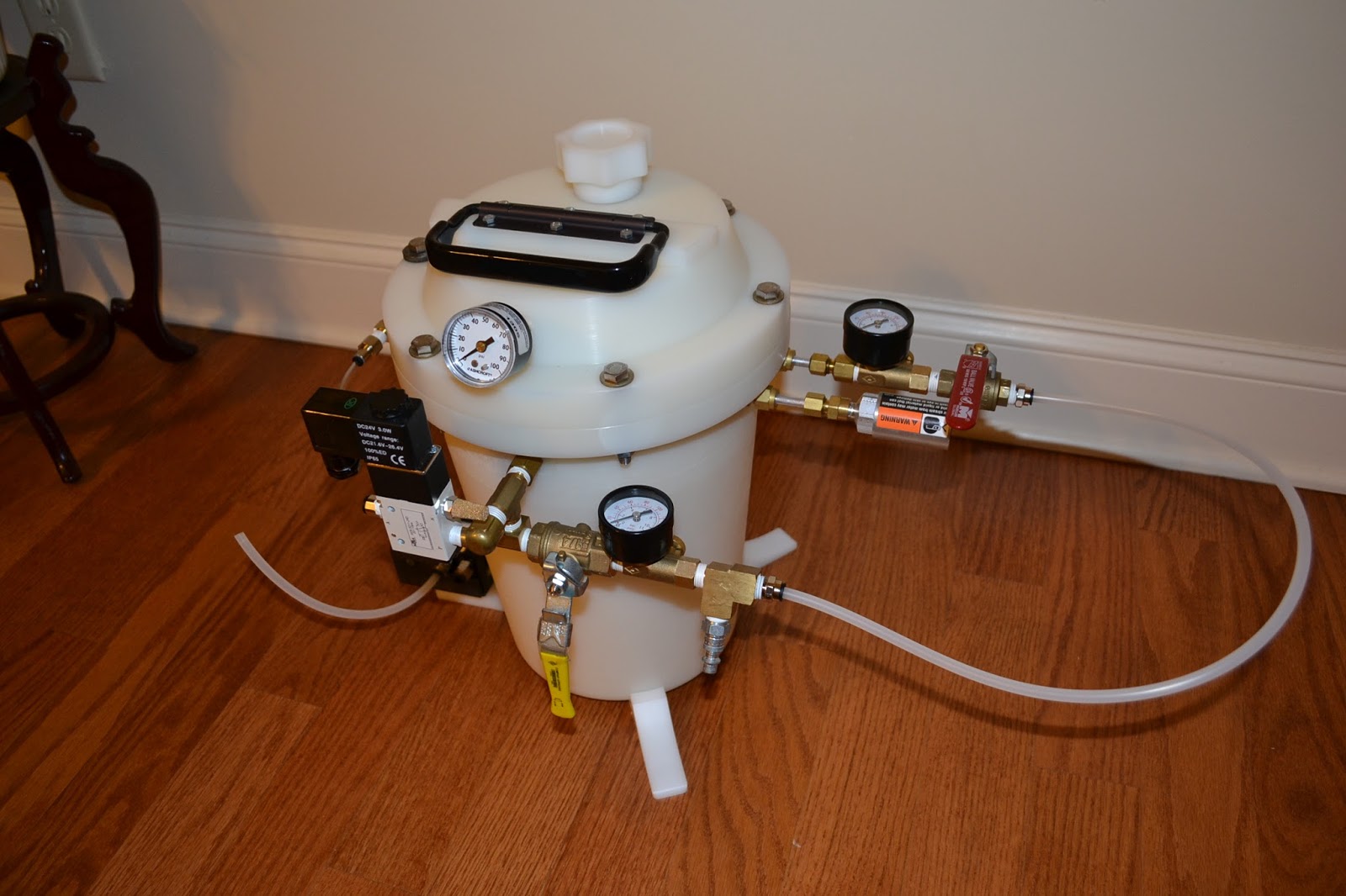
Here is a photo of the agitator built to specs.
If anyone is interested in this kind of engineering work, I will be glad to re-direct them to him. John is versatile, works on tight budgets and schedules, and very proficient in Autocad, Inventor etc.
John designed a portable agitator, a device used for mixing low-viscosity liquids or liquids with small-size solids.
Mixing is performed by a propeller driven by an internal pneumatic system, and not using an electrical motor, as shown in the diagram below.
The whole contraption is made of plastic, calculated for a maximum internal pressure of 80 psi.
The liquids are poured in manually, through PRV-07 (features a screw-in lid). The mixed liquid is released through the pinch-valve PRV-06. The lid PRV-01 can be removed (8 screws) for inside cleaning.
The mixing capacity is 1 gallon, but it can be easily scaled, in both dimensions and power.
Here is a photo of the agitator built to specs.
If anyone is interested in this kind of engineering work, I will be glad to re-direct them to him. John is versatile, works on tight budgets and schedules, and very proficient in Autocad, Inventor etc.