Posts with «general» label

Teaching Electronics to Kids

My "Introduction to Practical Electronics for Children" course concluded successfully a few weeks back, before March break. Now, with schools closed for covid19, it would be a good time for the kids to practice soldering and learn by doing. At this stage, I think it is easy to expand their knowledge and skills in the field of electronics just by assembling kits.

Here are a few notes and observations from my teaching.
  • Each class had 6 groups of 3 students sharing a soldering station. This (not my decision) was probably based of space constraints (6 desks in a normal-sized classroom) and safety/supervision considerations. It worked pretty well: the 2 students (in each group) not soldering had time to observe, analyze, think and to ask lots of questions. Two professional teachers assisted, with supervision, helping the students and keeping discipline.
  • Each student had their own "HDSP clock" kit to assemble. It took 6 one-hour sessions to complete, with a success rate of about 95% (2 failures out of 38 assembled, because of solder bridges).
  • The intended "50% theory and 50% practice" ratio had quickly become 10/90. Still managed to introduce components (resistor, capacitor, crystal), electrical concepts (AC vs DC, voltage, resistance, current, frequency) and units of measures (Volts, Farads, Ohms, Hertz). We even talked about Tesla batteries :)
  • Some parts were lost (e.g. crystal) or damaged (dropped, then stepped on by accident) between or during the classes. The lesson learned is to have extras available.
  • Each student received individual instructions, guidance, assistance and supervision on soldering. We came up with the "3-second rule" to make a good soldering joint: hold the tip of the soldering iron in contact with the pad and the terminal for 3 seconds while touching and melting the solder wire on the tip.
  • Having students pay attention to the instructions was very important. It saves energy to talk once to the whole class, rather than answering the same question to each individual. (I also learned from professional teachers  the "1-2-3 eyes on me" attention-getter.)
  • Sockets for integrated circuits are a must in a beginner kit. Imagine fixing an IC soldered in the wrong orientation! (The "worst" that happened was that all 3 ICs in the kit were soldered directly onto the board, luckily in the correct orientation.) Also, silkscreen should be as detailed as possible, indicating the component's place. In case of the "HDSP clock" kit, the students were able to easily identify the placeholders for each component, just by using logic (except for the resistors; they learned quickly to bend the resistors' terminals).
  • Some of the most frequent mistakes were soldering bridges and filling empty holes with solder. Bridges were easily fixed (initially by me, then the students learned to do it themselves) using the copper wick/braid, and flux. To fix the solder-filled holes, I had to use a tailor pin (part of my EDC Swiss card).
  • Surprisingly, every student showed interest in working on, and completing, the kit. I think it was a successful experiment even for the school, in making "practical electronics" as part of their curriculum. Like in the old days of practical skills teaching (wood working for boys, sewing or cooking for girls), this course demonstrated that Grade 6 students are very capable and eager to acquire skills that may stay with them for life.
Wise time with Arduino 21 Mar 16:42
general  review  

Teardown of an Old Dimmer Switch

The 40+ year-old dimmer (made by Nortron Industries Limited in Milton, Ontario) in my attic broke down. Electronically, the dimming circuit still worked, but mechanically, the push button got stuck.
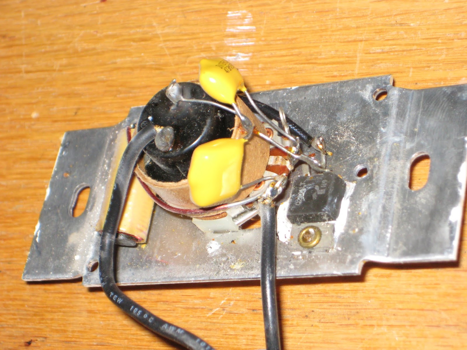
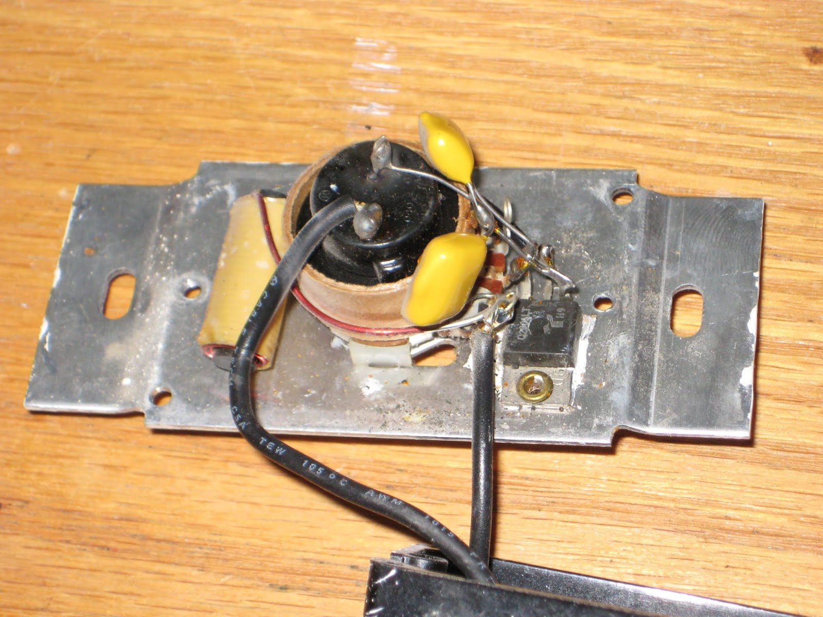
This is what's inside, for the curious.


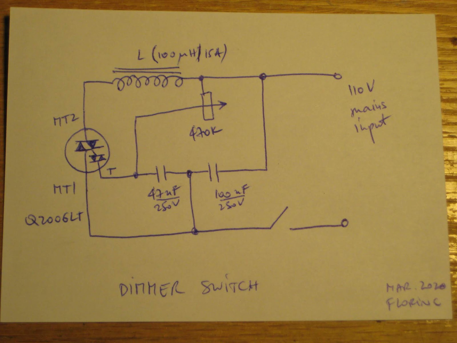
The active component in the circuit is Q2006LT, a "quadrac" which, according to the datasheet, "is an internally triggered Triac designed for AC switching and phase control applications. It is a Triac and DIAC in a single package, which saves user expense by eliminating the need for separate Triac and DIAC components".

The "reversed-engineered" schematic looks like this:


For those who want to understand more on how the triac-controlled dimmer works, this article provides an in-depth explanation.

The 250V capacitors may be reused in a Nixie high-voltage (~170V) power source. For a hoarder, both the choke and the potentiometer (push button removed) look good.

I will report back on the internals of the replacement switch in 40 years or so, when it breaks down. I hope I/it last(s) that long.

Wise time with Arduino 15 Mar 22:29
general  hacking  review  

Teardown of an Old Dimmer Switch

The 40+ year-old dimmer (made by Nortron Industries Limited in Milton, Ontario) in my attic broke down. Electronically, the dimming circuit still worked, but mechanically, the push button got stuck.
This is what's inside, for the curious.


The active component in the circuit is Q2006LT, a "quadrac" which, according to the datasheet, "is an internally triggered Triac designed for AC switching and phase control applications. It is a Triac and DIAC in a single package, which saves user expense by eliminating the need for separate Triac and DIAC components".

The "reversed-engineered" schematic looks like this:


For those who want to understand more on how the triac-controlled dimmer works, this article provides an in-depth explanation.

The 250V capacitors may be reused in a Nixie high-voltage (~170V) power source. For a hoarder, both the choke and the potentiometer (push button removed) look good.

I will report back on the internals of the replacement switch in 40 years or so, when it breaks down. I hope I/it last(s) that long.

Wise time with Arduino 15 Mar 22:29
general  hacking  review  

Introduction to practical electronics for children

I designed this 7-hour (one hour/day) course for 6 graders, as part of their STEM curriculum.
The goal is to introduce the children to practical electronics and teach them about:

1. electronic parts/components: how to identify/recognize them, how to measure (using a multi-meter), what they are used for (role in an electronic circuit):
  • resistors (current reduction), variable resistor/potentiometer, trimmer
  • capacitors (energy accumulator), variable capacitor
  • transistors (amplification)
  • coils (inductors)
  • diodes, LEDs
  • speakers. microphones
  • buttons, switches
  • integrated circuits, processors
  • displays
  • sensors (light, magnetic, proximity/infrared/ultrasound)
  • servo motors
  • relays
2. how to solder (using a soldering station), how to place and position parts on a board, how to check connection, how to follow steps of an instruction manual;

3. electricity and electronics concept:
  • voltage, current, resistance;
  • AC vs DC
  • digital vs analog
  • oscillation
  • rectification
  • amplification
  • series, parallel
  • voltage transformation (AC)
  • voltage regulation (AC, DC)
4. basic understanding/reading of schematics (wiring, electrical connections).


Required materials

Course schedule

Day 1
theory: introduction to components; presentation and identification (1/2 hour)
practice: beginning soldering (1/2 hour) LED + resistor, using flux, soldering wire, wick, on prototype PCBs;

Day 2
theory: introduction of a simple clock kit or another, more familiar to me, simple HDSP clock kit; assembly analysis, component placement and positioning;
practice: solder passive components on PCB; assemble the HDSP clock;

Day 3
theory: more on components; introduction to schematics;
practice: solder the active components of the clock kit;

Day 4
theory: electricity concepts (digital vs analog);
practice: finishing up the kit assembly; power, test, use;

Day 5
theory: electricity concepts (voltage, current, resistance); example of other kits;
practice: learn to use an ohm/volt/meter;

Day 6
theory: electronics concepts (oscillation, rectification, amplification, sound generation etc.);
practice: bring an electronic toy, working or not; disassembly, analysis, repair (if needed);

Day 7
practice: continuation from Day 6; identification of components used in the toy; understanding of how it works; modding/expanding functionality/adding LEDs, speaker, buttons etc.;


We are already on "Day 3", but behind schedule. Soldering is harder for the kids than I originally thought. One thing that I overlooked was that each student needs individual attention/supervision on the practical side (soldering, component placement etc.). Half hour per day of hands-on practice is definitely too short at this level. The schedule may be a little aggressive for the average Grade 6, probably better suited for older and more disciplined students. In any case, I am working on adjusting the content of the course and the feedback I receive is amazing. Kids really enjoy the fact that it is practical and some of them are amazed when they see the LEDs they soldered actually lighting up.


hidapitester – Command-line program to exercise HIDAPI

To help diagnose USB HID communication and to test out updates to hidapi, I wrote hidapitester. It is a command-line program that allows you to exercise just about every aspect of hidapi. Pre-built binaries for MacOS, Windows, and Linux Ubuntu x64. I’ve found it very useful. You can use it to: Scan for connected HID [...]
Todbot 14 Jun 05:30
general  

Oberheim Matrix 6r firmware update!

I upgraded the firmware on my beloved-but-long-unused 1986 Oberheim Matrix 6r! These synths are the royalty of analog fatness. I love their sound. This is the result I was looking for: It’s remarkably clean inside for a machine made in 1986. I acquired it used in the early 90s. Just look at the bank of [...]
Todbot 04 Jun 20:47
general  

HIDPyToy – GUI to test USB HID devices

Here is HIDPyToy. It’s a small app written in PyQt using the hid Python package to talk to USB HID devices (like Teensy RawHID or blink(1) USB RGB LEDs). Pre-build binaries are available for MacOS and Windows. HIDPyToy allows you to exercise pretty much the entire hidapi library from Python. You can: List for all [...]
Todbot 04 Jun 05:26
general  

ILOVELAMP: my Supplyframe DesignLab residency project

For four months this year I had a residency at the Supplyframe DesignLab.  I worked on “ILOVELAMP“, a project experimenting with creating lamps with configurable light emitting surfaces using addressable LED strips. Check out the project: https://hackaday.io/project/20121-i-love-lamp
Todbot 28 Jul 18:55

Replacing the battery in a Macbook Pro Retina (late 2013)

I really like the generation previous to the current Macbook Pros. You know the ones. They had all the useful ports like USB-A, HDMI, an SD Card slot, and MagSafe!  And it had a long-lived battery in a thin case. That is my Macbook Pro. And it’s wonderful. But now 3.5 years on, the once [...]
Todbot 09 Jul 03:31
general  

Learning Fusion 360 via 3d-printed iPhone tripod mounts

Here’s how I taught myself Fusion360 by updating a 3d-printable iPhone tripod mount I found on Thingiverse. Several years ago, I needed a tripod mount for my iPhone, so like anyone with a 3d printer at the time, I headed to Thingiverse and found this awesome tripod mount by haasebert. It has some very clever [...]
Todbot 07 Feb 23:09
general