Posts with «featured» label

Upgrade a sewing machine into an automatic embroidery rig

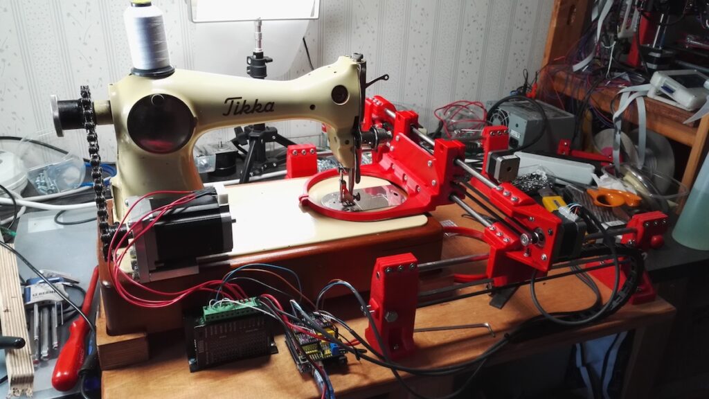
A needle and thread is extremely useful if you need to fasten a few pieces of fabric or sew on a button, and a sewing machine takes things up several notches in speed an accuracy. This venerable machine, however, can now be enhanced with a trio of stepper motors under Arduino Uno GRBL control to take things to an entirely new level.

The “Self-Made Embroidery Machine” employs a setup very similar to a 3D printer or CNC router. Two steppers move the fabric around, while a third actuates the needle. This allows the user to program in decorative shapes and patterns as shown in the video below, and the build process is well documented if you’d like to build your own!

Sewing machine part is any old or new sewing machine. Only change for original is stepper motor with synchronised pulley system (chain/belt drive) and more embroidery friendly presser foot. It is recommended to use older sewing machine, way more convenient to mount stepper motor to cast iron and prices are relatively cheap.

XY movement consists mainly 3D printed parts, 12 pcs and similar parts known from self build 3D printers. Both axes use GT2 belts, NEMA 17 steppers and both directions are fully scalable.

Synchronous movement comes from Arduino powered GRBL G-code interpreter, it is mouthful, but basically machine moves using G-code send to Arduino. It is not that complicated and it is only carrier like any other one when going from system to another one.

Now we have movement and code, but how to make nice shapes and export to G-code. It is nothing to do with medieval sorcery, it is a matter of downloading Inkscape and extension called Inkstitch.

Help and examples how to use Inkstitch extension can be found address above. End result should be really close to hobby level embroidery machines, just slower speed. After all, embroidery machine is nothing more than overgrown sewing machine.

Convert a Dremel tool into an Arduino-controlled CNC machine

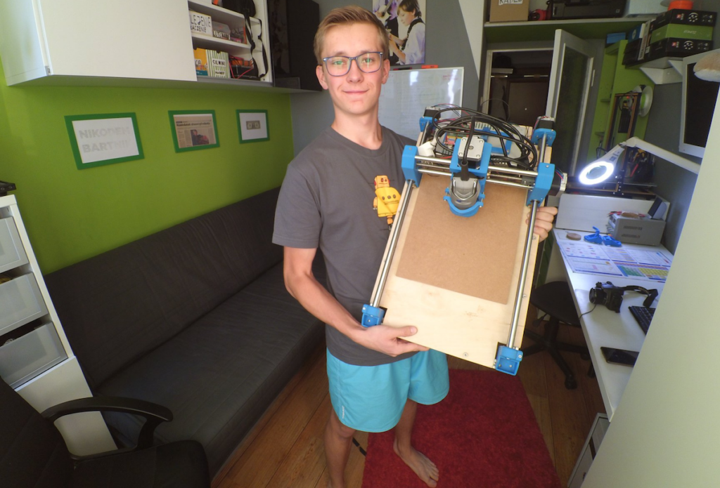
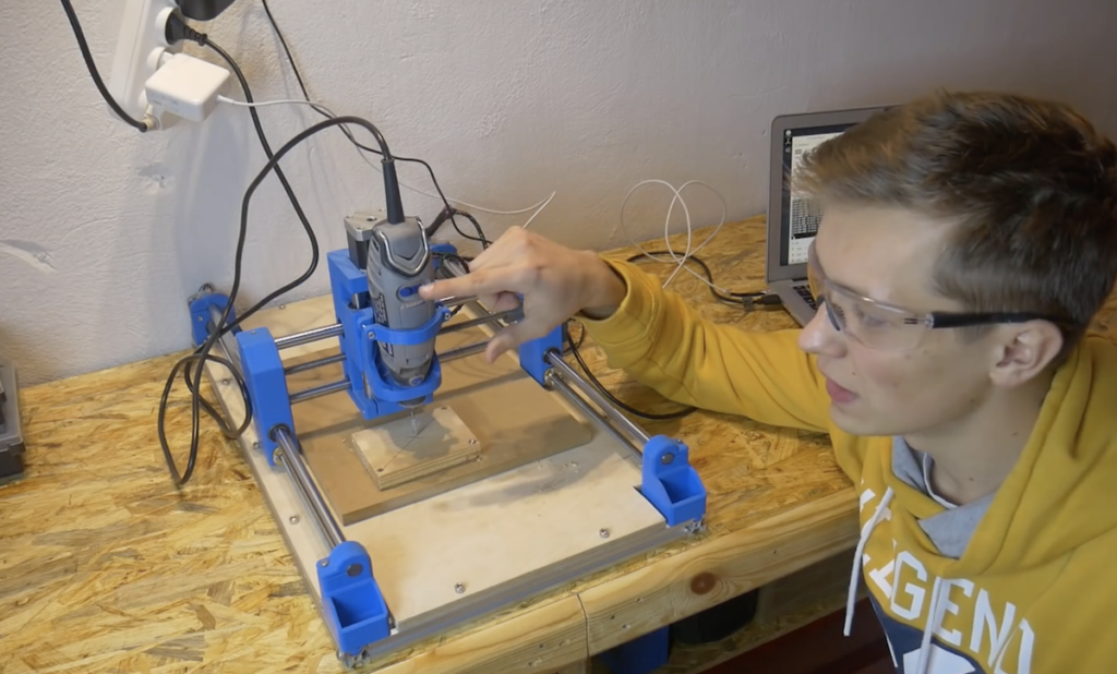
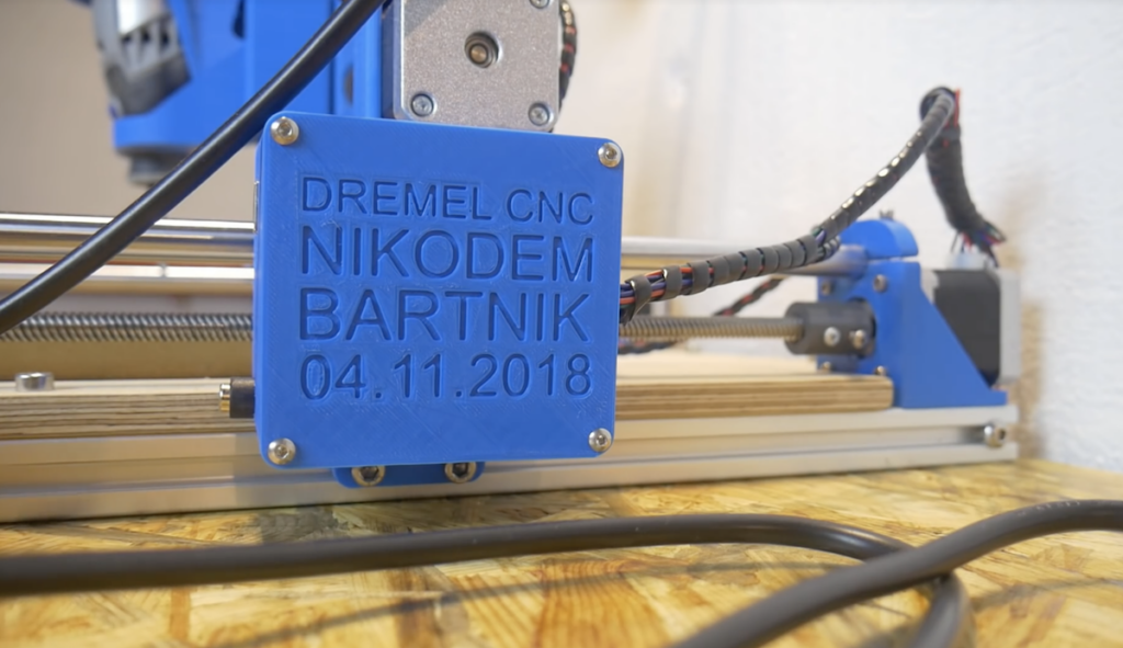
3D printers get most of the attention in maker-fabrication news, but other computerized tools, like laser cutters and CNC routers, can also be extremely useful. In fact, Nikodem Bartnik decided to create his own Dremel-based machine constructed out of 3D-printed parts and aluminum profiles. 

Electronics include an Arduino Uno and CNC stepper shield running GRBL for control, along with some NEMA 17 steppers and motor drivers, a relay for the Dremel, and a 12V / 30A power supply.

As with many other projects, his build went through several iterations, but the final results—seen in the video below—are quite good. The machine, which only cost him around $300, is able to mill MDF and acrylic.

If you’d like to make your own, Bartnik outlines his design in the first video below, then shows how to use it in the second. 

Customize your coffee cups with the Mug-O-Matic!

In order to inspire the next generation of scientists and engineers, Michael Graham (AKA EngineerDog) has come up with a robot that automatically draws on coffee mugs with a marker—and potentially much more. 

In its nominal configuration, the Mug-O-Matic is controlled by an Arduino Nano with a custom TinyCNC board, and uses a trio of small servo motors for cup plotting.

Additionally, the device can be reconfigured into a wide variety of robotic forms, and features 60+ compatible parts with which to do so. 

Mug-O-Matic is a 3-axis drawing robot that can customize coffee mugs! This capable little robot can draw anything you want via manual control, Bluetooth, calculated algorithms, or even g-code. So you can enjoy your custom mug creation, then wipe it clean. You could make it totally different every day for a year, and not make the same thing twice!

Its little buddy, the Desktop Sentry, is a pan-tilt turret that guards your desk! Also controlled via joystick, Bluetooth, algorithms, or G-code, this device can automatically guard your space with a laser or a rubber band launcher, or be used for light writing.

The intent of this project is to produce fun and accessible educational tools. We want to encourage people to engage in tinkering and making things, because the creative process is a powerful way to learn.

If you’d like to get to work on your own Mug-O-Matic, more info can be found here, including a parts list for the build. It is also slated for a release on Crowd Supply, which will likely make things easier and less expensive if you’re willing to wait!

(Almost) autonomous kids’ vehicle with Arduino

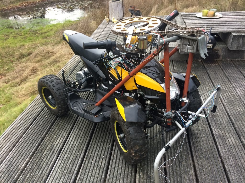
While the world seems to be focusing on self-driving cars, maker Sieuwe Elferink has instead turned his attention to creating a semi-autonomous kids’ four-wheeler. As of now, the modified device can steer itself within a set of lines, and stop for pedestrians and inanimate objects.

The augmented vehicle uses an Arduino Nano for control, plus a pair of TCRT5000 sensors attached to tubing on the sides to pick up boundary lines. Obstacle avoidance is via an ultrasonic sensor on the front. Four relays are used to activate a former windshield wiper motor for steering through a chain and sprocket system, along with the vehicle’s original motor for propulsion.

The build process is documented here, while code and an electrical schematic is available on GitHub.

Creep out guests with an Arduino-controlled teddy bear

Halloween has become something of a hacker holiday, giving creative people the world over a chance to show off their spooky animatronic inventions outside without neighborhood scrutiny. This year, Instructables user “gocivici” created a display inspired by the doll in a rocking chair featured in the movie Anabelle, but decided to use an Arduino-infused teddy bear instead. 

The setup is simple but effective, using an Arduino Nano and solenoid to rock the chair. The bear’s head rotates using another Arduino board—an Uno this time—along with a second solenoid and 3D-printed assembly stuffed inside. Control is accomplished via a small wireless remote, though a motion sensor could also be employed.

Arduino PRO Gateway for LoRa now available for pre-order

We are very happy to announce the Arduino PRO Gateway for LoRa!

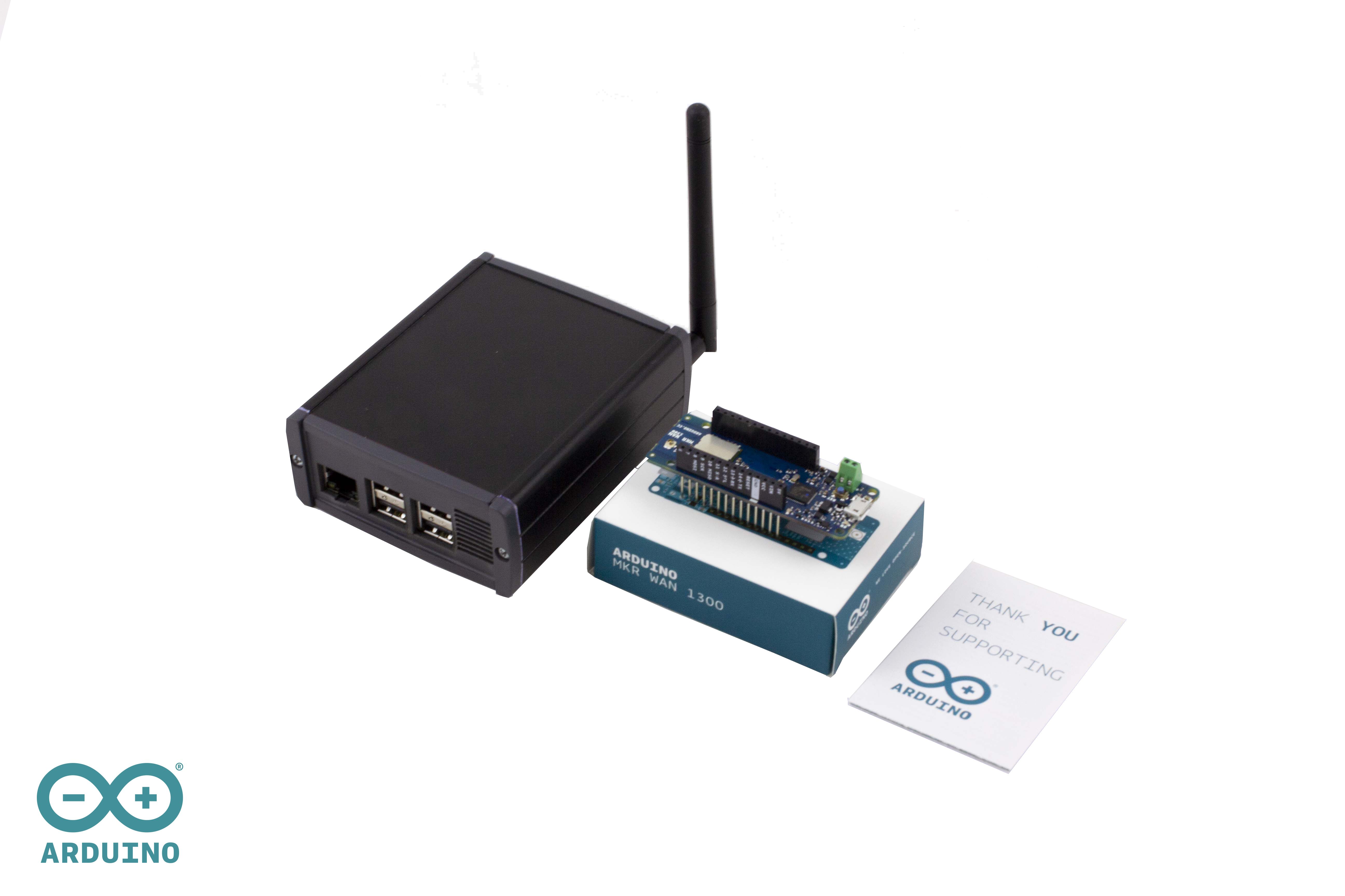
Combined with Arduino MKR WAN 1300 IoT nodes it makes an ideal solution for a wide range of applications, like smart agriculture, smart cities and building automation – and many other remote monitoring applications requiring long range, low power wireless connectivity.

The gateway can be used globally and enables multiple channel management. By supporting advanced features like Listen Before Talk (LBT), it allows users to transmit at higher power on the first free channel, achieving longer ranges than conventional gateways for LoRa. 

Arduino continues its mission of making complex technology easy enough for anyone to use. Customers of the Arduino PRO Gateway will be given exclusive beta access to the Arduino IoT Cloud, which makes installation, provisioning and remote management of the gateway incredibly simple through the popular Arduino Create cloud platform.

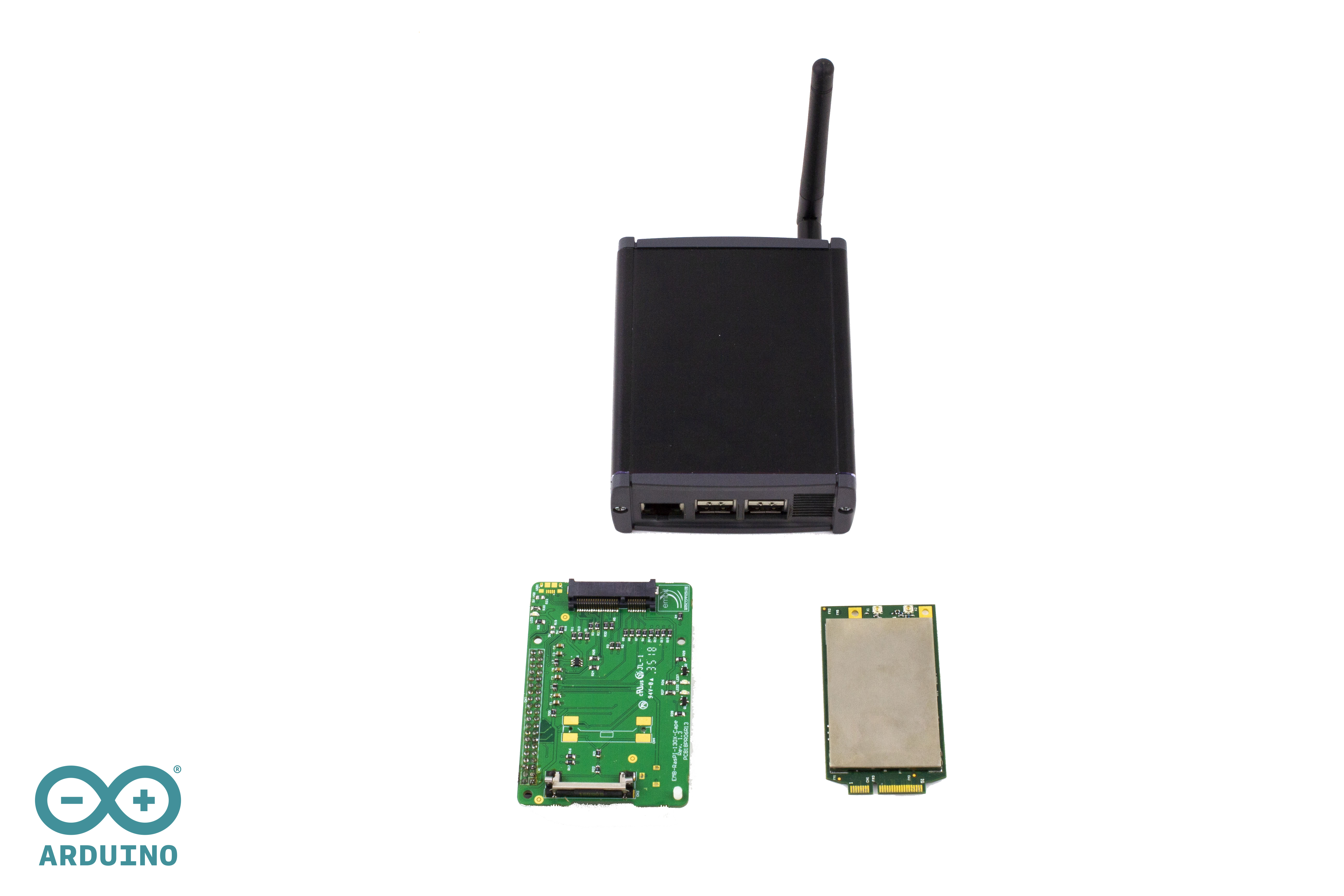
The gateway features the advanced Embit EMB-LR1301-mPCIe module, hosted by a Raspberry Pi 3 B+ SBC, in a rugged aluminum enclosure. The gateway comes pre-installed with an optimized packet forwarder and a carrier grade Network server for LoRa WAN that is running on the Arduino Cloud provided by A2A Smart City (part of the A2A Group).

Technical Specifications

  • Chipset: Semtech SX1301
  • Modulation: LoRa Spread Spectrum, FSK, GFSK 868MHz (EU) / 915MHz (US)
  • Number of Channels: 8 LoRa Channels
  • Operating Frequency: 868MHz (EU) / 915MHz (US)
  • Frequency Range: 860MHz to 1020MHz
  • Operating Temperature: -40°C to +85°C
  • RF Output Power: Up to +27dBm
  • Sensitivity: Up to -137dBm
  • Interfaces for the LoRa Module:  mPCIe (SPI / I2C / UART / GPIOs) :
  • Dimensions: 71x40x1mm
  • Operating Voltage: +5V
  • Additional Features:
    • Listen Before Talk (LBT) Capability (for improved transmission power management),
    • On-board uFL antenna connector
    • FPGA support for LoRa Spectral Scan


The Arduino Pro Gateway for LoRa (868 MHz , EU version) can be pre-ordered from the Arduino Store.

Arduino Blog 14 Nov 10:39

Dual Arduino “CNC” control

Generally when you work with CNC machinery, you program it on a computer, then allow a controller to automatically run through a cutting routine. Arduino boards have long been used for this kind of control through the grbl software package, but YouTuber Electronoobs decided to do things a bit differently.

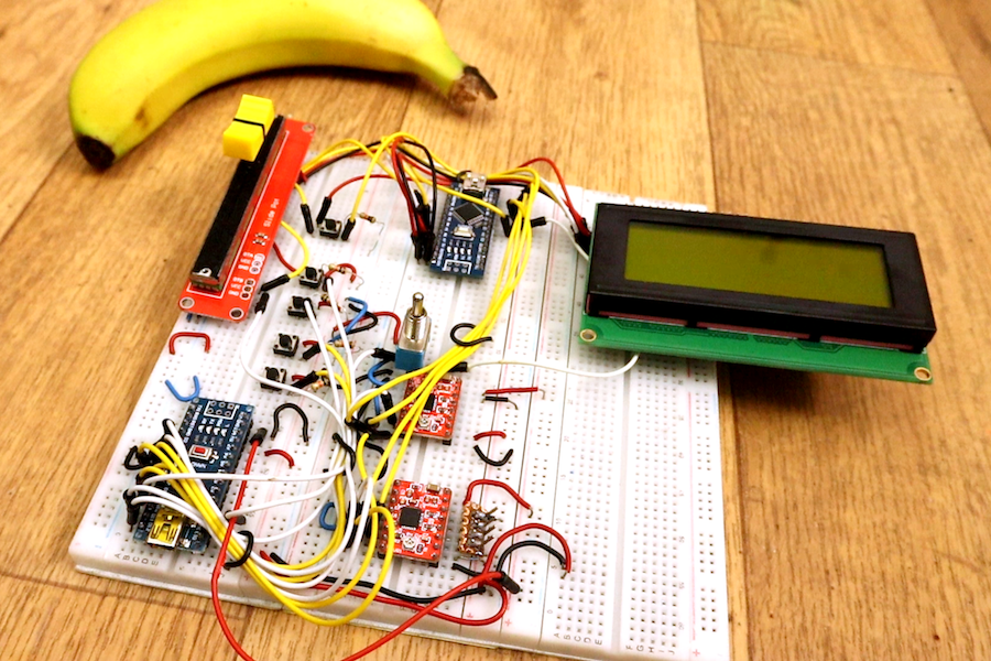
His setup takes input from a potentiometer and several buttons, enabling manual control of his stepper motor-driven router. An Arduino Nano powers the motors through a pair of stepper drivers, while a second Nano is then used to output distance information on an LCD screen, letting him view exactly where his cutter is at a glance.

Why use 2 Arduinos? Well, if I use only one, the code would be very difficult with too much interruptions. We have to create pulses for the motors and print on the LCD at the same time. I’ve done that and each time I was printing on the LCD, there was a small pause in the motor rotation, and if the refresh rate is fast, the motors will have a pause each time and we don’t want that. That’s why I use 2 Arduinos. One will create the pulses for the motors and the other one will count the steps and print the distance and speed.

We have 2 step motors. I’ve used NEMA 17. Each with a A4988 driver. This driver needs 3 signals from the Arduino. Enable, direction and steps. The enable pin is connected to a toggle switch so we could start to stop the motors manually. The toggle switch is also connected to the Arduinos so we could know when the motors are enabled or not. To control speed we use a lineal potentiometer and to move axis and reset position, some push buttons with pulldowns. To print the distance, I’ve used an I2S LCD screen of 20×4 but you will have the code for the 16×2 version of LCD as well.

Besides adding a nice readout to the machine, this concept could certainly form the basis for all manner of other stepper-driven devices.

Arduino Mega controls this amazing water organ

Earlier this year, artist Niklas Roy was invited to participate in the Drehmoment art festival that takes place in the south-west of Germany. The “catch” to this festival is that each artist was invited to team up with a local company to take advantage of their products and resources. Of these was cleaning equipment brand Kärcher, known for their pressure washers.

With this company’s backing, Roy put together a musical water fountain powered by eight pressure washers, dubbing it the “Wasserorgel von Winnenden,” or “Water Organ of Winnenden”—the location of Kärcher’s headquarters. 

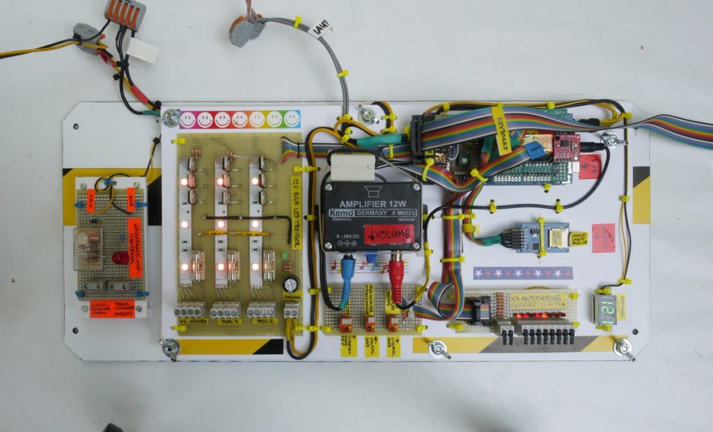
The installation is controlled by an Arduino Mega, along with supporting electronics including a Music Maker Shield and solid state relays to activate the pressure washers. During the festival, passerby were invited play some tunes using a 3D-printed keyboard made to withstand the elements and less-than-gentle interactions.

The brain of the Wasserorgel was an Arduino MEGA 2560, stacked with an Adafruit Music Maker Shield. The MIDI synthesizer of the shield generated the instrument sounds based on the input coming from a self-built, 3D-printed keyboard. The keyboard was designed solid enough to withstand weather and the misguided enthusiasm of drunk people at 3 ‘o clock at night. The program on the Arduino translated the keystrokes into water and light effects by switching 12V RGB LEDs via darlington transistors and the eight pressure sprayers via solid state relays. Five of the pressure sprayer fountains were installed on top of the main basin, one was installed on top of an existing fountain and two were installed on the roof of the Kronenplatz-building.

You can find more information in Roy’s project write-up, and see it in action below!

Vintage-style clock made from individual LEDs

If you’ve ever wanted a vintage-style timepiece, or to test your soldering abilities, this clock by YouTuber Electronoobs will let you do both at once. 

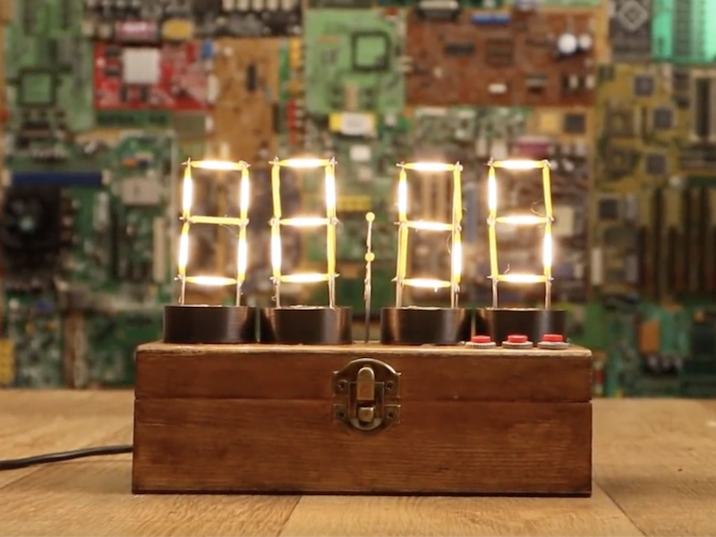
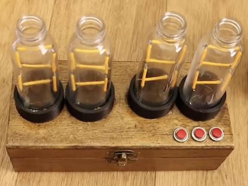
It features four display modules that resemble Nixie tubes, each made out of LED filaments soldered onto a steel wire frame. If you find soldering enjoyable and relaxing, this is likely a good project for you; though if not, there are of course other options. 

The device is controlled by an Arduino Nano, along with a MAX7219 display driver to power the LEDs as needed. An RTC module keeps things “ticking” at the correct pace, and a pair of buttons on top of the wooden enclose allow the time to be adjusted as needed.

I’ve made some “Nixie” tubes. These are actually 7-segment displays made with filament LEDs but placed in a plastic bottle so it will have a more vintage nixie look. To control the LEDs I’m using the MAX7219 driver that could control 4 x 7-segment displays. To get the real time, I’m using the DS3231 module that works with an I2C communication so it’s easy to use. The project also has 2 push buttons to set the hour and minute. All is inside a wood case painted with varnish so it will look more vintage.

Check it out in the video below, or see the build write-up for more info.

Hands on with the Arduino FPGA

All of the tools you need to work with the FPGA Arduino — the Vidor — are now in the wild!

We reported earlier that a series of French blog posts finally showed how all the pieces fit together to program the FPGA on the Arduino MKR4000 Vidor board. Of course, I wasn’t content to just read the Google translation, I had to break out the board and try myself.

I created a very simple starter template, a tool in C to do the bitstream conversion, required, and bundled it all together in one place. Here’s how you can use my starter kit to do your own FPGA designs using the Vidor. I’m going to assume you know about FPGA basics and Verilog. If you don’t, why not check out the FPGA boot camps first?

The first thing you’ll want to do is grab my GitHub repo. You’ll also need the Arduino IDE (a recent copy) and Intel’s Quartus software. Inside, you’ll find three directories, two of which contain slightly modified copies of original Arduino files. But before you start digging in, let’s get the high-level overview of the process.

Basic Concepts
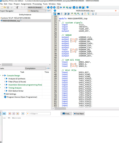
The FPGA onboard the Vidor is an Intel/Altera device so to configure it, we’ll use Quartus. Usually, Quartus handles everything including programming the device, but we can’t use it for that with the Vidor. Instead, we will have to tell the CPU how we want the FPGA configured and it will do it for us as part of our Arduino program (I really hate saying sketch).

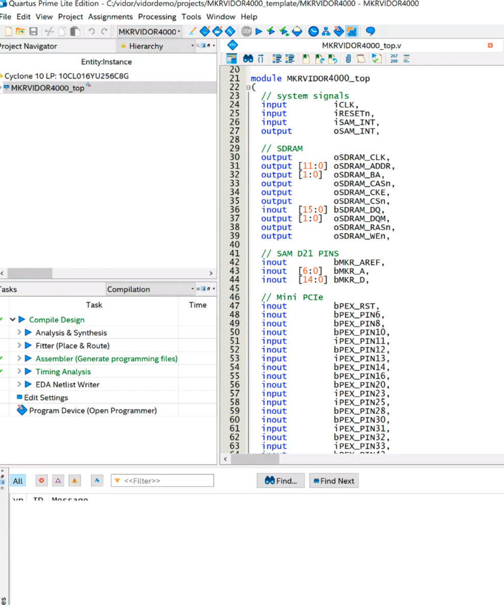
Quartus (see below) will take our Verilog files and create a ttf file that represents the configuration bitstream. This is just an ASCII text file full of decimal numbers. Unfortunately, the way the Vidor is set up, it needs the numbers bit reversed at the byte level. That is, 01 in the ttf file needs to be 80 hex sent to the FPGA.

Arduino supplies a Java class file to do the task, but I got frustrated because the class file needed Java 11 and I didn’t want to put it on every machine I use, so I just rewrote it in C. It is easy enough to port the algorithm, though. In the shell subdirectory, I have another example implementation using awk.

Once you have this stream of numbers, you can include it in an Arduino sketch with some boilerplate to enable the FPGA and load it. The standard program includes the file app.h which is just the output of the conversion program. There’s no C code in it, just comma-separated numbers that the main code will stick in an array at compile-time. Beyond that, it is a normal Arduino program and you can do what you like. Upload it and you’ll get the CPU and FPGA programmed all in one go.

There is one caveat. The FPGA code has a top-level block with lots of I/O pins defined and the corresponding constraints. You should be very careful not to change these or alter the pin constraints. If you drive a pin that’s already an output, for example, you could do real harm to the board. Because all the pins are shared, you have the same problem with the Arduino pins, too. If you are driving an output pin with the FPGA, you shouldn’t try to drive it with the CPU also. However, as you will see, it is perfectly fine to have the FPGA reading a pin from the CPU or vice versa. That’s good because it gives us a way to send data back and forth between them.

On to Code

I wanted something simple, and I didn’t want to accidentally modify the Arduino boilerplate Verilog. You could instantiate a Verilog module, but this would require passing all the I/O pins into the module or modifying the original code every time, both of which I wanted to avoid.

My answer was to use the Verilog `include directive inside the boilerplate. That way your code has access to everything the main module has, but you don’t have to change the main module. The only downside is that Quartus has a smart compile feature that can’t figure out when only an include file changes. So it wasn’t recompiling when I made changes. I turned that feature off in the Quartus options, so if you pick up my example project, you won’t have any problems.

Here’s my example user.v:

reg [27:0] hadcounter;
assign bMKR_D[6]=bMKR_D[5]?hadcounter[27]:hadcounter[21];

always @(posedge wOSC_CLK)
begin
   if (!rRESETCNT[5])
   begin
      hadcounter<=28'hfffffff;
   end
   else
   begin
      if (hadcounter==28'h0) hadcounter<=28'hffffffff; else hadcounter<=hadcounter-28'h1;
   end
end

In the real file, I left a lot of comments in that explains what all the main module has that you can use. But the above is the working part. I define a 28 bit counter. The bMKR_D array is the digital ports for the Arduino and I’m using pin 6 and 5 as an output and an input, respectively.

The assign statement says, in English, If D5 is high, connect the 27th bit of the counter to the LED. If it is low, connect the 21st bit. The rest of the code just makes the counter countdown. I reload the counter even though it would naturally roll over in case you want to fine tune it to a different frequency.

As the counter runs, bit 27 will toggle relatively slowly, but bit 21 will be a good bit faster — that’s just how a counter is. So by changing D5 you can make the LED blink slow or fast.

As Verilog goes, this isn’t very complicated or even useful, but it is simple and shows that we can share data with the CPU in both directions. If you open the example project in Quartus, all you really need to do is make any changes to user.v you like, add any other files you want to use and double-click the Compile Design task (see left). If you get a successful compile, you’ll find the ttf file in the output_files directory. That’s the file you need to process with either the Java program, the C program, or the awk script. Either way, collect the output as app.h and put it in the same directory as your Arduino code.

CPU Side

On the sketch side, you need to leave the template code alone since it turns on the FPGA clock, among other things. You’ll notice it also includes app.h and uses a file called jtag.c to communicate with the FPGA. I didn’t segregate the Arduino code into its own include because you probably have to change the setup function, and make changes in global space, but that could be arranged (perhaps make setup call cpu_setup and loop call cpu_loop or something).

If you want to remove the demo parts of the blink-sketch file, you can get rid of:

  • The definitions and calls related to FPGAVal, SPEED, and FPGALED
  • The Serial calls and definitions
  • Everything in the loop function

I left the unmodified code in the EmptySketch directory. Note in the demo code, though that SPEED is an output. This is set to D5, which is an input to the FPGA. By the same token, FPGALED corresponds to D6 and allows the CPU to read the state of the LED output.
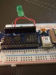
You will need an LED and dropping resistor on pin 6 unless you want to watch with a scope or a meter. I always keep some LEDs with built-in 5V dropping resistors handy, and even at 3.3V it was plenty bright. With one of those, you can just stick the wires right into the header socket on the board. Don’t try that with a regular LED, though!

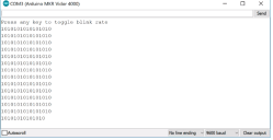
Once you run the sketch, you can open the serial monitor or any terminal at 9600 baud. There will be a message saying you can press any key to change the blink rate. Of course, since the serial monitor doesn’t allow you to press keys exactly, you’ll have to enter something and hit enter (set “No line ending” at the bottom of the monitor screen), but on a real terminal, any character press should do it.

The main code is pretty simple:

void loop() {
static int oldstate=-1;
static int linect=0;
int state;
if (Serial.read()!=-1)
  {
  FPGAVal=FPGAVal==HIGH?LOW:HIGH;
  digitalWrite(SPEED,FPGAVal);
  }
state=digitalRead(FPGALED);
if (state!=oldstate)
  {
  Serial.print(state);
  if (++linect==16)
    {
    Serial.println();
    linect=0;
    }
  oldstate=state;
  }
}

In the loop, if serial data appears, we just toggle the output going to the FPGA. We also sample the LED output on every pass. If it has changed from the last time, we write the new state to the terminal and then update the state so we don’t flood the screen with repeated characters. A lot of the code is just tracking when we’ve written enough to start a new line.

Vidor’s Hello World

I wanted to get everything you needed in one place and an example that would be easy to follow yet show the critical working parts. It would be easy enough to use the shared I/O pins to do SPI, for example, and then you could trade data with the FPGA quite easily. Don’t forget there’s Arduino IP (intellectual property; sort of library subroutines for FPGAs) in the IP directory, too, if you want to use it.

Now you just need a project idea that makes sense for an FPGA. Our personal favorite would be a logic analyzer. The CPU can talk to the PC, set up triggers and then let the FPGA do the dirty work of finding the trigger and storing data as fast as possible. If you want something less ambitious, it is very simple to create totally autonomous PWM outputs on an FPGA. We could see this being handy for robotics or machine control where you want a very rapid sequence of outputs without CPU intervention or overhead.

Of course, not every project has to make sense. If you are just wanting to learn about FPGAs there are plenty of projects you could do with a CPU but are easy enough to build in an FPGA (the classic traffic light comes to mind). Of course, with the Vidor you have an opportunity to use a blend of FPGA code and CPU code, which is kind of the point.