Paul Stoffregen did it again: the Teensy 4.0 has been released. The latest in the Teensy microcontroller development board line, the 4.0 returns to the smaller form-factor last seen with the 3.2, as opposed to the larger 3.5 and 3.6 boards.
Don’t let the smaller size fool you; the 4.0 is based on an ARM Cortex M7 running at 600 MHz (!), the fastest microcontroller you can get in 2019, and testing on real-world examples shows it executing code more than five times faster than the Teensy 3.6, and fifteen times faster than the Teensy 3.2. Of course, the new board is also packed with periperals, including two 480 Mbps USB ports, 3 digital audio interfaces, 3 CAN busses, and multiple SPI/I2C/serial interfaces backed with integrated FIFOs. Programming? Easy: there’s an add-on to the Arduino IDE called Teensyduino that “just works”. And it rings up at an MSRP of just $19.95; a welcomed price point, but not unexpected for a microcontroller breakout board.
The board launches today, but I had a chance to test drive a couple of them in one of the East Coast Hackaday labs over the past few days. So, let’s have a closer look.
First Impressions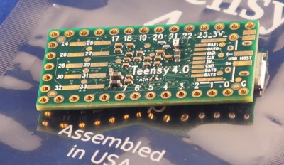
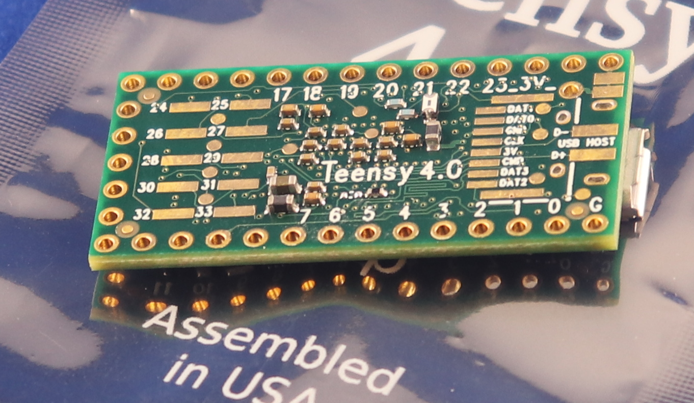
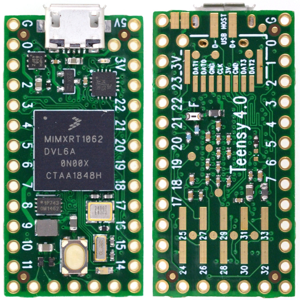
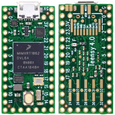
The board looks superficially similar to the older 3.2, at least from the top. There’s the usual dual row of pin headers you can plug into a breadboard, a micro-USB connector, and reset button. A new red LED near the USB connector gives you some status information, while the traditional “Arduino LED” is orange. Flip the board over, and you start to see some of the extra power this board wields. Besides ten more GPIO pins, there are pads for an SD card interface using 4-bit SDIO, and D+ and D- lines for the second 480 Mbps USB interface. The unmarked round pads are test points used in manufacturing and are no-connects from the end-user’s perspective.
Teensy 3.2 Everything Killer?
When doing hardware reviews it’s crucial to choose the right comparison hardware. I think the best comparison in this case is between the two boards that share the same form factor; the Teensy 4.0 and the 3.2. I’ve chosen not to make the comparison with the Teensy 3.5 and 3.6, which are priced a little higher, in a larger form factor, and have SD card slots soldered on.
 Incredibly, the Teensy 4.0 is priced at $19.95, as opposed to the $19.80 Teensy 3.2. What does that extra fifteen cents buy? First, there’s performance. The 4.0’s 600 MHz clock vs the 72 MHz on the 3.2 doesn’t tell the whole story. The Cortex M7 on the 4.0 is a dual-issue superscalar processor capable of executing up to two 32-bit instructions per clock cycle; initial tests showed this happening between 40-50% of the time on Arduino-compiled code. Additionally, the Cortex-M7 is the first ARM microcontroller with branch prediction. While on the Cortex M4, a branch always takes 3 clock cycles, after a few passes through a loop, for instance, the Cortex M7 can begin executing correctly-predicted branches in a single clock. This is technology originally pioneered in supercomputers that you can use in your next Halloween costume.
 Then, there’s floating-point. Veteran embedded programmers may have a bias against floating-point code, and with good reason. Without native floating-point instructions, these operations must be emulated, and run very slowly. The same thing happens with double-precision operations on a processor which only supports single-precision instructions. While Cortex-M4 processors support single-precision floating-point, the Cortex-M7’s include native double-precision instructions, so if you need the extra precision afforded by doubles, you’re not going to take a huge performance hit: basically, doubles seem to execute in only twice as many cycles as floats.
The Cortex-M7 on this board also supports tightly-coupled memory (TCM), which provides fast access like a cache, but without the non-determinism that can complicate hard real-time applications — one of the problems with other high-power microcontrollers. The 64-bit ITCM bus can fetch 64-bits, while two dedicated 32-bit buses (DTCM) can fetch up to two instructions from the TCM each cycle – these buses are separate from the main AXI bus used to communicate with other memory and peripherals. The Teensyduino environment automatically allocates code and statically allocated memory into the DTCM area, which can be up to 512K in size, although you can override the default behavior with some command-line switches. Memory that isn’t accessed by the tightly-coupled buses is optimized for access by the peripherals using DMA.
Spec Sheet
Despite its size, there’s a lot to this board and the chip it carries, so here’s condensed spec list:
- ARM Cortex-M7 at 600 MHz
- 1024K RAM (512K is tightly coupled)
- 2048K Flash (64K reserved for recovery & EEPROM emulation)
- 2 USB ports, both 480 MBit/sec
- 3 CAN Bus (1 with CAN FD)
- 2 I2S Digital Audio
- 1 S/PDIF Digital Audio
- 1 SDIO (4 bit) native SD
- 3 SPI, all with 16 word FIFO
- 3 I2C, all with 4 byte FIFO
- 7 Serial, all with 4 byte FIFO
- 32 general purpose DMA channels
- 31 PWM pins
- 40 digital pins, all interrupt capable
- 14 analog pins, 2 ADCs on chip
- Cryptographic Acceleration
- Random Number Generator
- RTC for date/time
- Programmable FlexIO
- Pixel Processing Pipeline
- Peripheral cross triggering
- Power On/Off management
The board consumes around 100 mA with a 600 MHz clock. Although I didn’t try it myself with the evaluation boards I have here, Paul notes that it can be overclocked for a performance boost. It also supports dynamic clock scaling: the instruction clock speed is decoupled from the peripherals, so that baud rates, audio sample rates, and timing functions continue to function properly if you change the CPU speed.
For the ultimate in power savings, you can shut the board off by adding a pushbutton to the On/Off pin. Pressing the button for more than five seconds disables the 3.3 V supply; a subsequent brief press will turn it back on. This doesn’t affect the real-time-clock (RTC) functionality, however: connecting a coin cell to the VBAT terminal will keep the time and date counter going.
Hands-On Benchmarks
Higher is better
| Board |
CoreMark |
| Teensy 4.0 |
2313.57 |
| Teensy 3.6 |
440.72 |
| Sparkfun ESP32 Thing |
351.33 |
| Teensy 3.5 |
265.50 |
| Teensy 3.2 |
218.26 |
| Metro M4 Grand Central |
214.85 |
| Arduino Due |
94.95 |
| Arduino Zero |
56.86 |
| Arduino Mega |
7.03 |
To see how fast this thing really is, Paul ported the CoreMark embedded-processor benchmark to the Arduino environment. (Note that CoreMark seems to be a registered trademark of the Embedded Microprocessor Benchmark Consortium (EEMBC)). This synthetic benchmark tests performance managing linked lists, doing matrix multiplies, and executing state machine code. He reports the following scores for a number of boards (larger numbers are better).
I was able to verify the Teensy 4.0 and 3.2 numbers; my 3.6 must have sprouted legs and walked off somewhere, and I didn’t have any of the other boards handy for testing. Using my numbers (nearly identical to those above), the 4.0 is around ten times as fast as the 3.2.
Since the CoreMark code is a “synthetic” benchmark, Paul wanted to test the new board in a more realistic scenario. In another GitHub repo, he has some code to do an RSA signature with a 2048-bit key. This is a processor-intensive operation, believe me — I had to implement it once in Lua (don’t ask!). Here are the scores for the same boards (lower numbers are better).
Lower is better
| Board |
Seconds |
| Teensy 4.0 |
0.085 |
| Teensy 3.6 |
0.474 |
| Sparkfun ESP32 Thing |
0.518 |
| Metro M4 Grand Central |
0.840 |
| Teensy 3.5 |
0.909 |
| Teensy 3.2 |
1.325 |
| Arduino Due |
1.901 |
| Arduino Zero |
9.638 |
Again, I was able to verify the numbers for the Teensy 3.2 and 4.0 boards. In this case, the 4.0 is around fifteen times as fast as the 3.2.
If you have any of these, or other Arduino-compatible boards lying around, clone one or both of these repos, open the respective *.ino file from either one, and test them out. Feel free to report results in the comments below.
15 Seconds to Sanity
One of the new features of the Teensy 4.0 is the automatic recovery process, which restores the board to a known good state without the need for a PC connection. If you press and hold the reset button for 15 seconds, the red LED will flash to indicate you’ve entered restore mode. Once you release the button, the red LED will illuminate while the flash memory is erased and re-written with the traditional Arduino “blink” program. Once the re-write is complete, the blink program is run and the orange LED begins blinking, just like on every Arduino-compatible for the past decade and a half. It’s DFU mode without the need for host computer or known-working binary. These used to be key components for hardware-based restore and now they’re part of the board itself.
Why would you want to do this? In a nutshell, because USB itself is a train-wreck. On top of an insanely sprawling and complex protocol, there are charge-only cables sans data pins lurking in your junk box, operating system bugs waiting to trip you up (looking at you, Windows 7), and a whole host of other issues that cause serious head-scratching when things stop working. This can be especially confusing with native-USB boards like the Teensy 4.0; while the built-in USB functionality is amazingly powerful, and can be used in a wide variety of ways, when something stops working, you’re not always sure how to get back on track. Now, you are – just press the button.
What Can You Do with a 600 MHz Microcontroller?
Paul envisions this Teensy 4.0 being used for polyphonic audio synthesis, running moderately complex machine learning algorithms, and real-time audio analysis. In many cases, the first level of processing on data-intensive input devices can now be moved from a host computer to the external microcontroller, narrowing the bandwidth required to the host system. And for projects driving a display, the built-in pixel processing pipeline can also accelerate graphics operations, offloading this work from the CPU.
There will be some fraction of hackers that will still wonder why we need a 600 MHz microcontroller; another fraction will have already needed it yesterday. In between, most users will take some time to figure out what doors this opens up. The reality is that our tools constrain not only our current designs, but also, to some extent, our imagination. A 15x performance improvement over the current tiny development board you may be using could enable some new and exciting applications, and you, dear reader, are the one who makes them happen. So, drive home a different way from work tonight, sleep on the sofa instead of the bed, or use whatever other tricks you have to shock your brain into creativity and figure out what you could really do with this thing. It’s a lot more than you can do with a 555. For that matter, it’s a lot more than most computers could do in the 90s.