Posts with «featured» label

Control model trains wirelessly with your smartphone

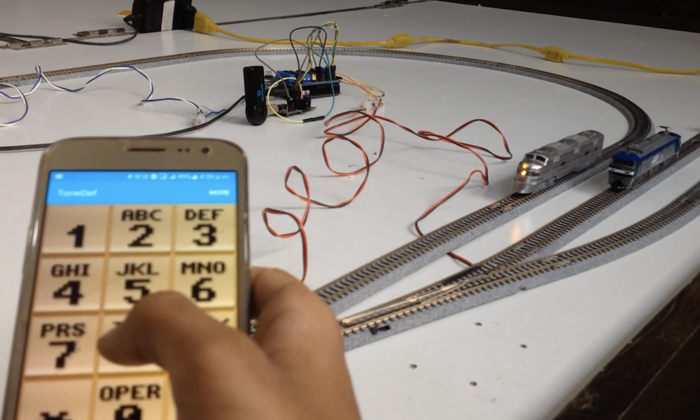
Model trains have been a staple of DIY hobbiysts for generations, and while wireless control options can be purchased, KushagraK7’s hack lets you use your phone instead.

The setup consists of an Arduino Uno, along with a motor driver shield to vary the trains’s peed and direction, as well as flip turnouts to allow for different sections of track to be used.

The system employs a novel interface system, where an off-the-shelf Bluetooth receiver passes DTMF (telephone dial tones) to a decoder board, which then sends this decoded data on to the Arduino. While some might opt for an HC-05 Bluetooth module or similar, this enables control with a standard tone generator app, and the phone could even be physically connected via a stereo cable if convenient.

An e-skateboard controller made from scratch with Arduino

Last June, Timo Brinschein bought a Qu4tro electric skateboard with hopes of using it for fun and commuting duties. Unfortunately, while the skateboard itself worked well, the remote had many shortcomings.

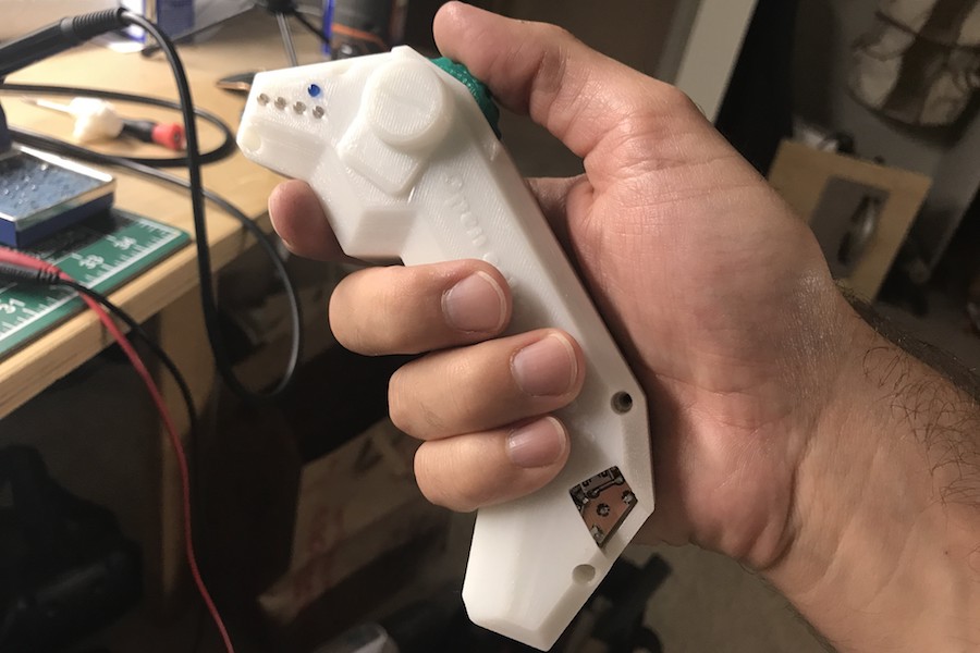
Since replacing the skateboard’s controls entirely was out of reach, he instead settled on the “small” job of reverse engineering and swapping out the wireless controller for one of his own designs. 

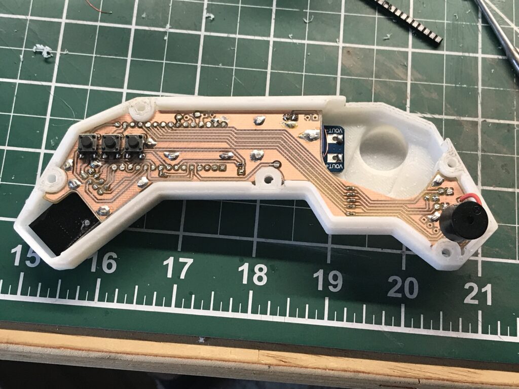
The resulting build uses an Arduino Nano as the brains of the device, along with the well-known nRF24L0+ module for wireless communication. Everything is housed inside a custom 3D-printed enclosure. 

Code for the project is available on GitHub, and print files for the excellent control handle is on Thingiverse.

Electronoobs creates his own Bluetooth-controlled Daft Punk helmet

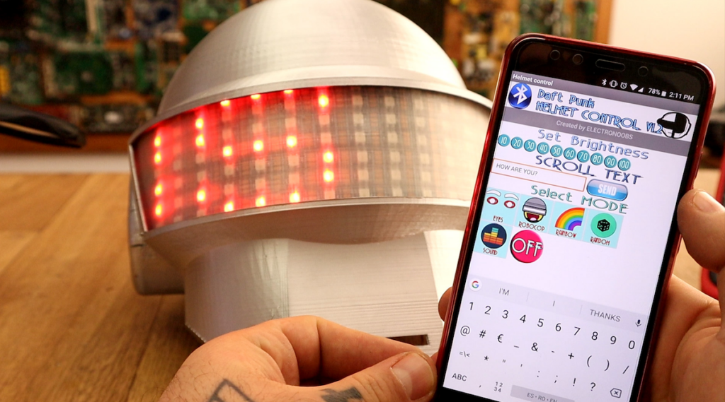
If you like electronic music, you’ve certainly admired Daft Punk’s glowing electronic helmets. While the originals are amazing, as shown in this Electronoobs tutorial, you can now make a very good replica for around $20 and 30 hours of print time.

Print files for the helmet itself are based on this Thomas Bangalter build by the Ruiz Brothers, and similar to that one, a good amount of sanding and finishing was needed to give it a metallic look. 

Electronoobs’ helmet features seven WS2812 RGB LED strips, all connected to an Arduino Nano. Everything is controlled over Bluetooth by a custom Android app made with the MIT App Inventor, along with a microphone that allows the visor to react to music.

High school play gets a simulated sports scoreboard

Maker “DJ’s Fantasi” is the technical director at his local high school’s theater arts program, and when the director of their winter production of Disney’s High School Musical requested a scoreboard prop, he excitedly set to work. 

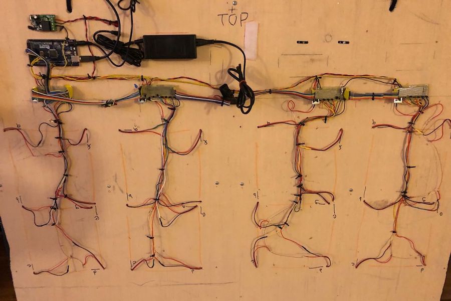
The resulting build consists of four 7-segment displays, lit up by strips of non-programmable LEDs. 

Numbers on the device are shown with the help of an Arduino Mega, which takes input via a single-channel remote. Seven I/O pins are used to indicate each segment to be displayed, and another four multiplex the signal into the required four digits.

While a more general input device could be used, this particular scoreboard was especially set up for this musical, sequencing through numbers that correspond to the performance on command.

More details on this impressive project can be found here.

Build a tachometer for your metal lathe with Arduino

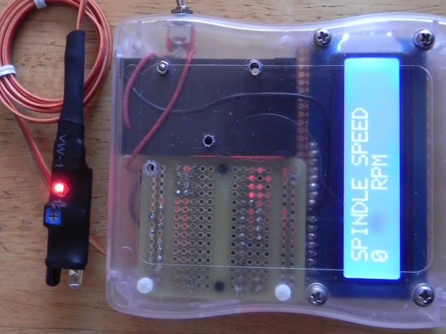
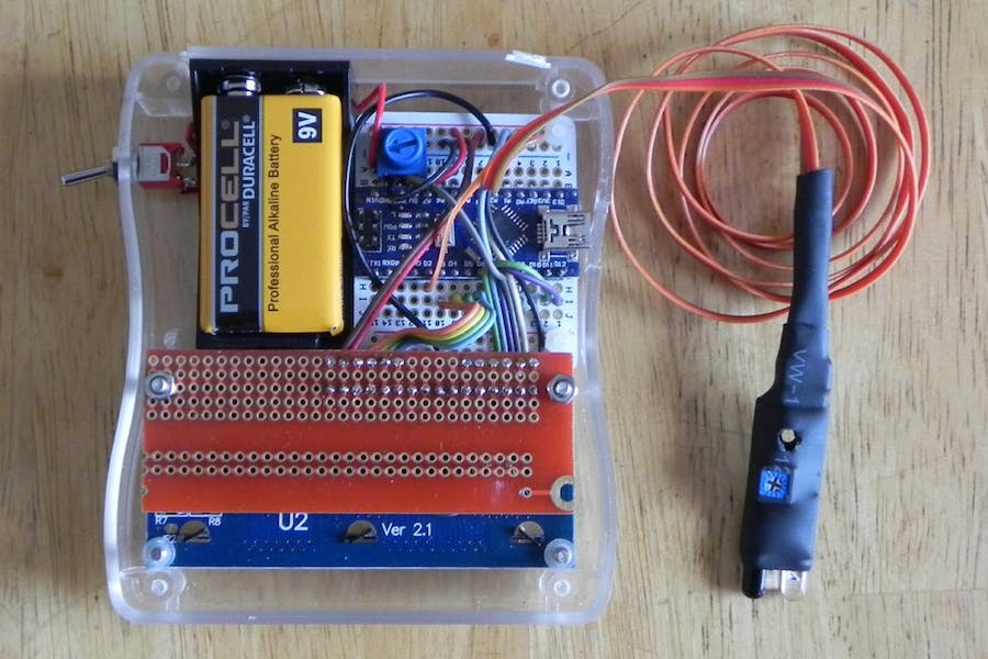
If you manage to get a small lathe in your home shop, it will likely come with a dial to adjust the speed, but it may not have a tachometer to tell you if it’s actually spinning at your desired setting. Rather than accept this imprecision on his model, hacker Tony Scarpelli designed his own non-contact tachometer using an Arduino Nano.

The build is ingeniously simple, and mounts an infrared proximity sensor near gearing in the back of the lathe’s headstock. White paper is placed on this rotating surface, allowing the sensor to tell between this marker and the otherwise dark surface as it spins. Sensor pulses are recorded by the Arduino, which outputs RPM values on a small 16×2 LCD display.

Star Trek tricorder-style heart rate monitor

A heart rate monitor can be an important tool for tracking fitness and exertion levels, but what if you want something a bit more interesting style-wise? For a novel idea, be sure to check out the project shown below from “Taste The Code.”

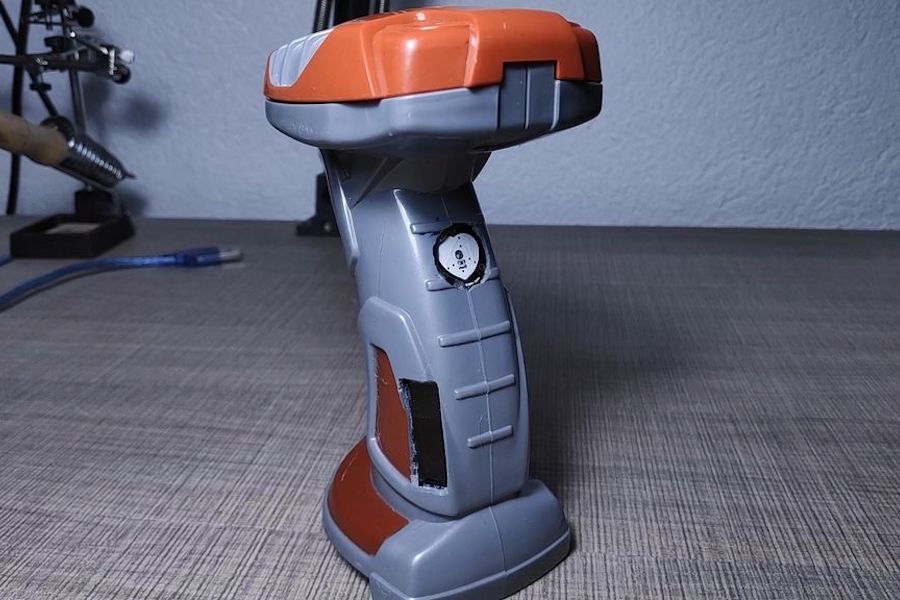
In it, Blagojce Kolicoski turns a handle used for launching rotating toys into something reminiscent of a tricorder from Star Trek.

The build stuffs an Arduino, a pulse sensor, and a tiny OLED display into the handle, which conveniently already had accommodations for three AA batteries. This, along with the monitor’s I2C connection, meant that wiring everything up was quite simple. 

Want to make your own? Instructions are available here, while code can be found on GitHub.

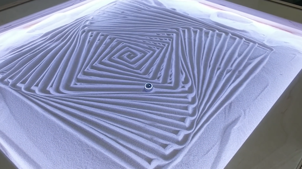
Create mesmerizing designs in the sand with this Arduino-controlled Zen table!

A sandbox game generally refers to an open world computer simulation, but Tim Callinan’s fall semester project takes things in a different direction—an actual sandbox controlled by an Arduino and gShield.

Callinan’s Zen table is capable of producing complicated designs in the sand, using a single steel marble that appears to magically move across the surface by itself.

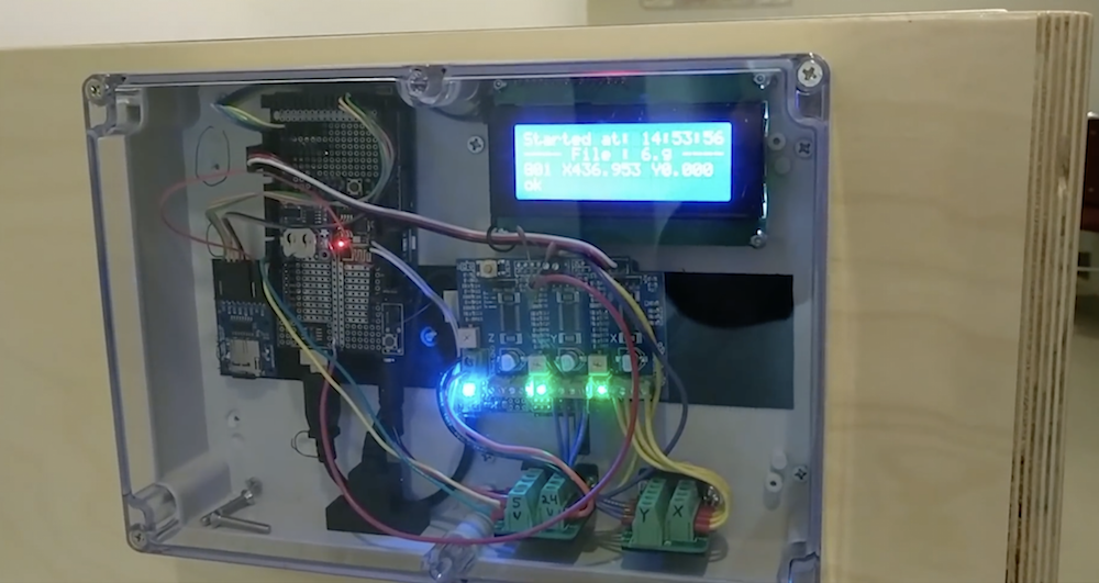
Underneath the sand assembly is a stepper-controlled gantry that acts like a laser cutter or other CNC tool, dragging the marble around with a powerful magnet. The results are stars, rotating squares, and other kaleidoscopic patterns, beautifully edge-lit with a series of RGB LEDs.

Several other classmates were involved in making this build a reality, including Mark Morello, who wired and programmed the device.

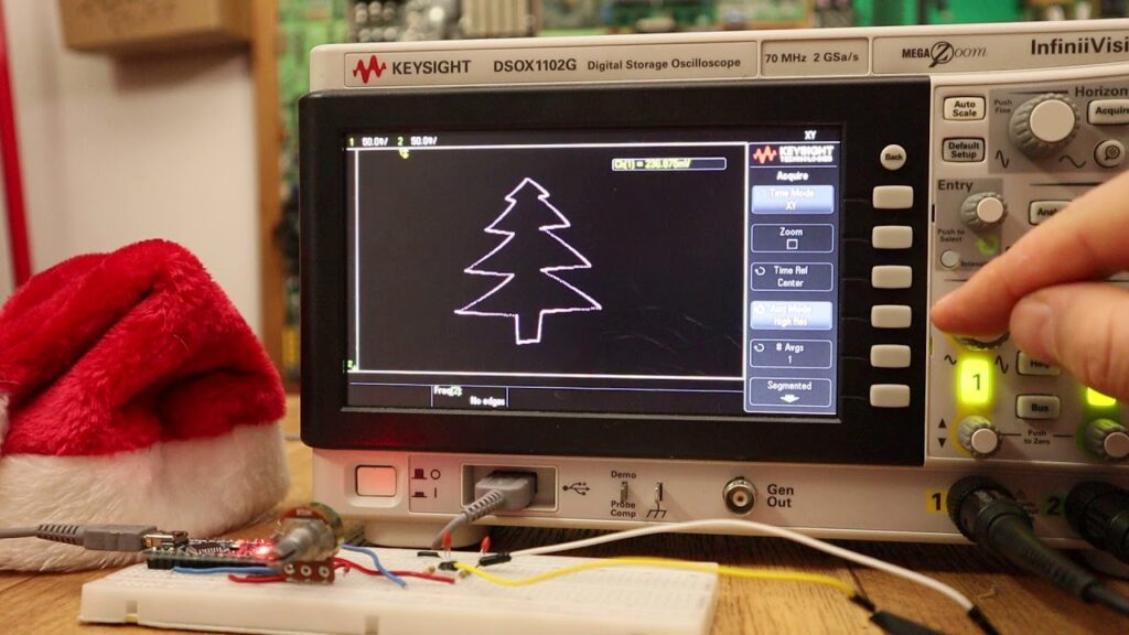
Draw on an oscilloscope with Arduino

If you’ve ever wanted to plot shapes using an oscilloscope, YouTuber Electronoobs reveals the tricks in his latest video. In it, he draws a Christmas tree, along with a few other shapes, and while that holiday is now past, there’s always the 2019. Of course, you don’t have to wait, as these concepts can be applied to anything you like throughout the year!

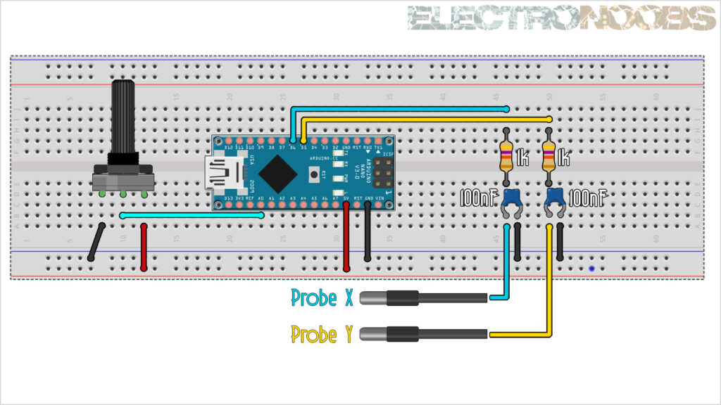
In the video, Electronoobs uses an Arduino Nano to produce PWM signals on two channels, filtering each of them with a capacitor and resistor. As he explains, shapes must be fairly simple, and end in the same place they started. Even with these restrictions, once the oscilloscope it turned to x/y plot mode and the signal is tuned in, the results are quite good.

In this tutorial we will use two pins from the Arduino to create fast PWM signals. With a small filter, we change the amplitude of that signal according to the width of the PWM pulse. By that, we can draw shapes on the oscilloscope when in XY mode.

Code for the project can be found in Electronoobs’ write-up here.

OpenLH robot automates biological exploration

If you’d like an easy way to accomplish repetitive biological experiments, the OpenLH presents a great option for automating these tasks. 

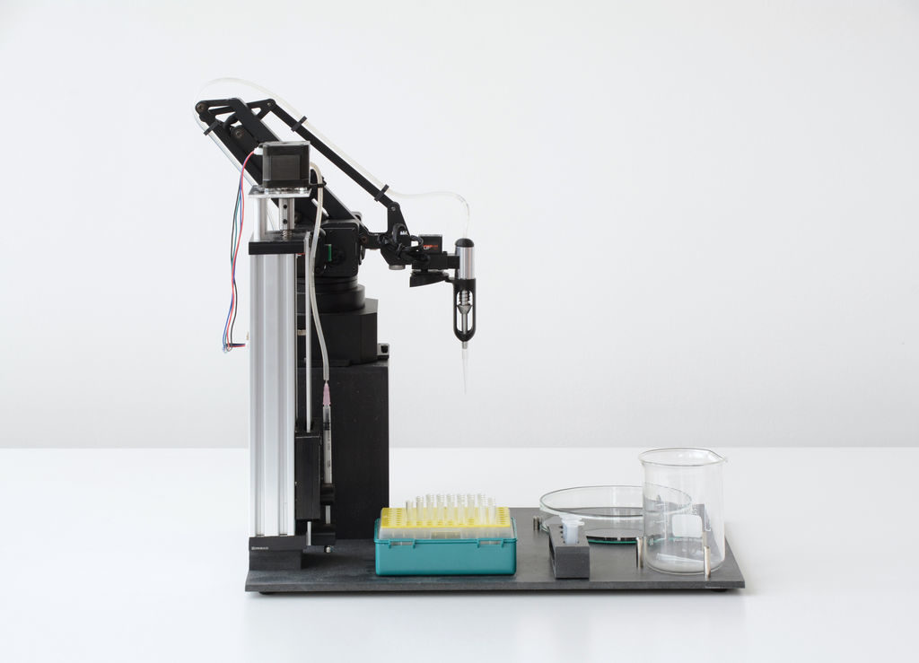
The heart of the system is the Arduino Mega-controlled uArm Swift Pro robot, which is equipped with a custom end effector and syringe pump. This enables it to dispense liquids with an average error of just .15 microliters.

A Python/Blockly interface allows the OpenLH to be set up for creative exploration, and because of the arm’s versatility, it could later be modified for 3D printing, laser cutting, or any number of other robotic duties. 

Liquid handling robots are robots that can move liquids with high accuracy allowing to conduct high throughput experiments such as large scale screenings, bioprinting and execution of different protocols in molecular microbiology without a human hand, most liquid handling platforms are limited to standard protocols.

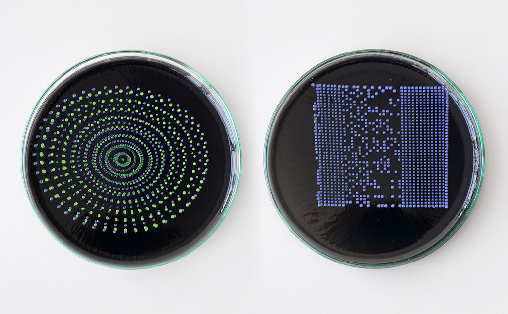
The OpenLH is based on an open source robotic arm (uArm Swift Pro) and allows creative exploration. With the decrease in cost of accurate robotic arms we wanted to create a liquid handling robot that will be easy to assemble, made by available components, will be as accurate as gold standard and will cost less than $1,000. In addition the OpenLH is extendable, meaning more features can be added such as a camera for image analysis and real time decision making or setting the arm on a linear actuator for a wider range. In order to control the arm we made a simple Blockly interface and a picture to print interface block for bioprinting images.

We wanted to build a tool that would be used by students, bioartists, biohackers and community biology labs around the world.

The OpenLH can be seen in the video below, bioprinting with pigment-expressing E. coli bacteria.

An inexpensive device for analyzing roasted coffee beans

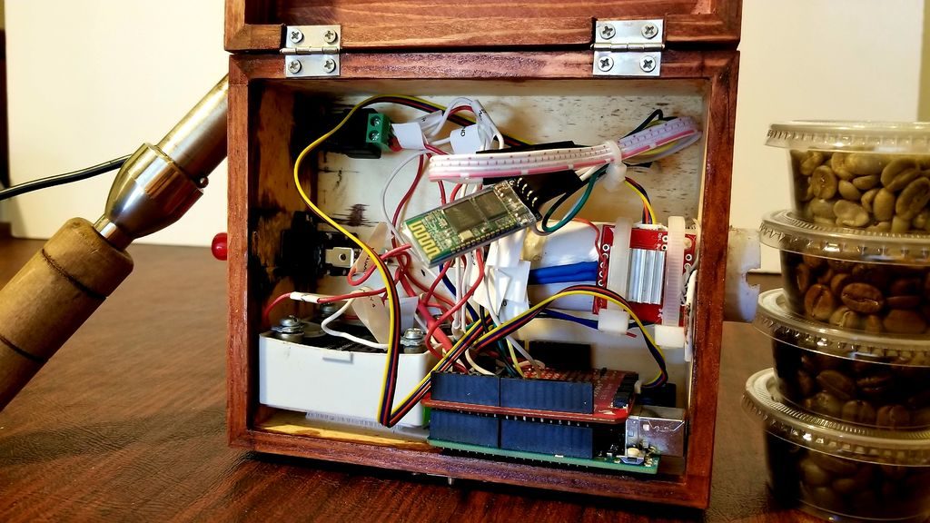
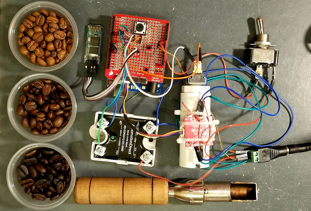
While you may not consider in detail how your coffee is roasted, those that produce it must pay special attention to make sure that the end product is consistent. Equipment to help analyze roasted coffee is normally quite expensive, but using a near-infrared sensor, Arduino Uno and Bluetooth module, Spencer Corry was able to make his own analysis setup.

As shown in the video below, after calibration, beans are inserted into the analysis chamber using a tryer scoop. Light is shined onto the roasted beans, and the intensity of the reflected near-infrared radiation is analyzed in six different wavelengths. Intensity data is then transmitted via Bluetooth to a smart device, which can be used to make sure things are roasted perfectly.

There has recently been a growth of small roasting companies offering custom in-house roasts. These companies are looking for less expensive alternatives to hiring and training a roast master or using the expensive Agtron Process Analyzer. The Degree of Roast Infrared Analyzer for Coffee Roasters, as described in this document, is meant to be an inexpensive means of measuring the degree of roast of coffee beans. The Degree of Roast Infrared Analyzer uses a tryer, a tool found on coffee roasters used to sample the coffee during roasting, to hold a sample of coffee. The tryer is inserted into the analyzer where the AS7263 NIR Spectral sensor is used to measure 6 different infrared bands (610, 680, 730, 760, 810, and 860nm). The reflectance measurements are transmitted via Bluetooth and can then be correlated to the degree of roast. The analyzer must first be calibrated by pressing a button on the inside of the box in which the PVC is used as a white balance as it has a relatively flat reflectance in the spectral range detected by the sensor.