Tutorial – LED Real Time Clock Temperature Sensor Shield for Arduino
In this tutorial we look at how to use the neat LED Real Time Clock Temperature Sensor Shield for Arduino from PMD Way. That’s a bit of a mouthful, however the shield does offer the following:
- four digit, seven-segment LED display
- DS1307 real-time clock IC
- three buttons
- four LEDs
- a active buzzer
- a light-dependent resistor (LDR)
- and a thermistor for measuring ambient temperature

The shield also arrives fully-assembled , so you can just plug it into your Arduino Uno or compatible board. Neat, beginners will love that. So let’s get started, by showing how each function can be used – then some example projects. In no particular order…
The buzzer
A high-pitched active buzzer is connected to digital pin D6 – which can be turned on and off with a simple digitalWrite() function. So let’s do that now, for example:
void setup() {
  // buzzer on digital pin 6
  pinMode(6, OUTPUT);
}

// the loop function runs over and over again forever
void loop() {
  digitalWrite(6, HIGH);   // turn the buzzer on (HIGH is the voltage level)
  delay(1000);                       // wait for a second
  digitalWrite(6, LOW);    // turn the buzzer off by making the voltage LOW
  delay(1000);                       // wait for a second
}
If there is a white sticker over your buzzer, remove it before uploading the sketch. Now for a quick video demonstration. Turn down your volume before playback.
The LEDs
Our shield has four LEDs, as shown below:
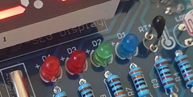
They’re labelled D1 through to D4, with D1 on the right-hand side. They are wired to digital outputs D2, D3, D4 and D5 respectively. Again, they can be used with digitalWrite() – so let’s do that now with a quick demonstration of some blinky goodness. Our sketch turns the LEDs on and off in sequential order. You can change the delay by altering the variable x:
void setup() {
  // initialize digital pin LED_BUILTIN as an output.
  pinMode(2, OUTPUT); // LED 1
  pinMode(3, OUTPUT); // LED 2
  pinMode(4, OUTPUT); // LED 3
  pinMode(5, OUTPUT); // LED 4
}

int x = 200;

void loop() {
  digitalWrite(2, HIGH);    // turn on LED1
  delay(x);
  digitalWrite(2, LOW);    // turn off LED1. Process repeats for the other three LEDs
  digitalWrite(3, HIGH);
  delay(x);
  digitalWrite(3, LOW);
  digitalWrite(4, HIGH);
  delay(x);
  digitalWrite(4, LOW);
  digitalWrite(5, HIGH);
  delay(x);
  digitalWrite(5, LOW);
}
And in action:
The Buttons
It is now time to pay attention to the three large buttons on the bottom-left of the shield. They look imposing however are just normal buttons, and from right-to-left are connected to digital pins D9, D10 and D11:
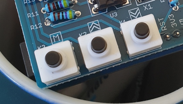
They are, however, wired without external pull-up or pull-down resistors so when initialising them in your Arduino sketch you need to activate the digital input’s internal pull-up resistor inside the microcontroller using:
pinMode(pin, INPUT_PULLUP);
Due to this, buttons are by default HIGH when not pressed. So when you press a button, they return LOW. The following sketch demonstrates the use of the buttons by lighting LEDs when pressed:
void setup() {
  // initalise digital pins for LEDs as outputs
  pinMode(2, OUTPUT); // LED 1
  pinMode(3, OUTPUT); // LED 2
  pinMode(4, OUTPUT); // LED 3

  // initalise digital pins for buttons as inputs
  // and initialise internal pullups
  pinMode(9, INPUT_PULLUP); // button K1
  pinMode(10, INPUT_PULLUP); // button K2
  pinMode(11, INPUT_PULLUP); // button K3
}

void loop()
{
  if (digitalRead(9) == LOW)
  {
    digitalWrite(2, HIGH);
    delay(10);
    digitalWrite(2, LOW);
  }

  if (digitalRead(10) == LOW)
  {
    digitalWrite(3, HIGH);
    delay(10);
    digitalWrite(3, LOW);
  }

  if (digitalRead(11) == LOW)
  {
    digitalWrite(4, HIGH);
    delay(10);
    digitalWrite(4, LOW);
  }
}
You can see these in action via the following video:
The Numerical LED Display
Our shield has a nice red four-digit, seven-segment LED clock display. We call it a clock display as there are colon LEDs between the second and third digit, just as a digital clock would usually have:

The display is controlled by a special IC, the Titan Micro TM1636:
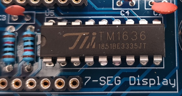
The TM1636 itself is an interesting part, so we’ll explain that in a separate tutorial in the near future. For now, back to the shield.
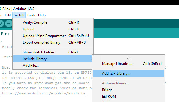
To control the LED display we need to install an Arduino library. In fact the shield needs four, so you can install them all at once now. Download the .zip file from here. Then expand that into your local download directory – it contains four library folders. You can then install them one at a time using the Arduino IDE’s Sketch > Include library > Add .zip library… command:
The supplied library offers five functions used to control the display.
.num(x);
…this displays a positive integer (whole number) between 0 and 9999.
.display(p,d);
… this shows a digit d in location p (locations from left to right are 3, 2, 1, 0)
.time(h,m)
… this is used to display time data (hours, minutes) easily. h is hours, m is minutes
.pointOn();
.pointOff();
… these turn the colon on … and off. And finally:
.clear();
… which clears the display to all off. At the start of the sketch, we need to use the library and initiate the instance of the display by inserting the following lines:
#include <TTSDisplay.h>
TTSDisplay rtcshield;
Don’t panic – the following sketch demonstrates the five functions described above:
#include <TTSDisplay.h>
TTSDisplay rtcshield;

int a = 0;
int b = 0;

void setup() {}

void loop()
{
  // display some numbers
  for (a = 4921; a < 5101; a++)
  {
    rtcshield.num(a);
    delay(10);
  }

  // clear display
  rtcshield.clear();

  // display individual digits
  for (a = 3; a >= 0; --a)
  {
    rtcshield.display(a, a);
    delay(1000);
    rtcshield.clear();
  }
  for (a = 3; a >= 0; --a)
  {
    rtcshield.display(a, a);
    delay(1000);
    rtcshield.clear();
  }

  // turn the colon and off
  for (a = 0; a < 5; a++)
  {
    rtcshield.pointOn();
    delay(500);
    rtcshield.pointOff();
    delay(500);
  }

  // demo the time display function
  rtcshield.pointOn();
  rtcshield.time(11, 57);
  delay(1000);
  rtcshield.time(11, 58);
  delay(1000);
  rtcshield.time(11, 59);
  delay(1000);
  rtcshield.time(12, 00);
  delay(1000);
}
And you can see it in action through the video below:
The LDR (Light Dependent Resistor)
LDRs are useful for giving basic light level measurements, and our shield has one connected to analog input pin A1. It’s the two-legged item with the squiggle on top as shown below:
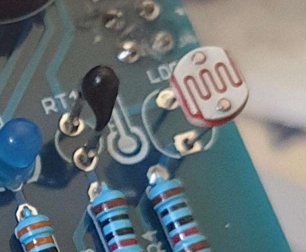
The resistance of LDRs change with light levels – the greater the light, the less the resistance. Thus by measuring the voltage of a current through the LDR with an analog input pin – you can get a numerical value proportional to the ambient light level. And that’s just what the following sketch does:
#include <TTSDisplay.h>
TTSDisplay rtcshield;

int a = 0;

void setup() {}
void loop()
{
  // read value of analog input
  a = analogRead(A1);
  // show value on display
  rtcshield.num(a);
  delay(100);
}
The Thermistor
A thermistor is a resistor whose resistance is relative to the ambient temperature. As the temperature increases, their resistance decreases. It’s the black part to the left of the LDR in the image below:
We can use this relationship between temperature and resistance to determine the ambient temperature. To keep things simple we won’t go into the theory – instead, just show you how to get a reading.
The thermistor circuit on our shield has the output connected to analog input zero, and we can use the library installed earlier to take care of the mathematics. Which just leaves us with the functions.
At the start of the sketch, we need to use the library and initiate the instance of the thermistor by inserting the following lines:
#include <TTSTemp.h>
TTSTemp temp;
… then use the following which returns a positive integer containing the temperature (so no freezing cold environments):
.get();
For our example, we’ll get the temperature and show it on the numerical display:
#include <TTSDisplay.h>
#include <TTSTemp.h>

TTSTemp temp;
TTSDisplay rtcshield;

int a = 0;

void setup() {}

void loop() {

  a = temp.get();
  rtcshield.num(a);
  delay(500);
}
And our thermometer in action. No video this time… a nice 24 degrees C in the office:

The Real-Time Clock
Our shield is fitted with a DS1307 real-time clock IC circuit and backup battery holder. If you insert a CR1220 battery, the RTC will remember the settings even if you remove the shield from the Arduino or if there’s a power blackout, board reset etc:

The DS1307 is incredibly popular and used in many projects and found on many inexpensive breakout boards. We have a separate tutorial on how to use the DS1307, so instead of repeating ourselves – please visit our specific DS1307 Arduino tutorial, then return when finished.
Where to from here?
We can image there are many practical uses for this shield, which will not only improve your Arduino coding skills but also have some useful applications. An example is given below, that you can use for learning or fun.
Temperature Alarm
This projects turns the shield into a temperature monitor – you can select a lower and upper temperature, and if the temperature goes outside that range the buzzer can sound until you press it.
Here’s the sketch:
#include <TTSDisplay.h>
#include <TTSTemp.h>

TTSTemp temp;
TTSDisplay rtcshield;

boolean alarmOnOff = false;
int highTemp = 40;
int lowTemp = 10;
int currentTemp;

void LEDsoff()
{
  // function to turn all alarm high/low LEDs off
  digitalWrite(2, LOW);
  digitalWrite(4, LOW);
}

void setup() {
  // initalise digital pins for LEDs and buzzer as outputs
  pinMode(2, OUTPUT); // LED 1
  pinMode(3, OUTPUT); // LED 2
  pinMode(4, OUTPUT); // LED 3
  pinMode(5, OUTPUT); // LED 4
  pinMode(6, OUTPUT); // buzzer

  // initalise digital pins for buttons as inputs
  // and initialise internal pullups
  pinMode(9, INPUT_PULLUP); // button K1
  pinMode(10, INPUT_PULLUP); // button K2
  pinMode(11, INPUT_PULLUP); // button K3
}

void loop()
{
  // get current temperature
  currentTemp = temp.get();

  // if current temperature is within set limts
  // show temperature on display

  if (currentTemp >= lowTemp || currentTemp <= highTemp)
    // if ambient temperature is less than high boundary
    // OR if ambient temperature is grater than low boundary
    // all is well
  {
    LEDsoff(); // turn off LEDs
    rtcshield.num(currentTemp);
  }

  // if current temperature is above set high bounday, show red LED and
  // show temperature on display
  // turn on buzzer if alarm is set to on (button K3)

  if (currentTemp > highTemp)
  {
    LEDsoff(); // turn off LEDs
    digitalWrite(4, HIGH); // turn on red LED
    rtcshield.num(currentTemp);
    if (alarmOnOff == true) {
      digitalWrite(6, HIGH); // buzzer on }
    }
  }

  // if current temperature is below set lower boundary, show blue LED and
  // show temperature on display
  // turn on buzzer if alarm is set to on (button K3)

  if (currentTemp < lowTemp)
  {
    LEDsoff(); // turn off LEDs
    digitalWrite(2, HIGH); // turn on blue LED
    rtcshield.num(currentTemp);
    if (alarmOnOff == true)
    {
      digitalWrite(6, HIGH); // buzzer on }
    }
  }
  // --------turn alarm on or off-----------------------------------------------------
  if (digitalRead(11) == LOW) // turn alarm on or off
  {
    alarmOnOff = !alarmOnOff;
    if (alarmOnOff == 0) {
      digitalWrite(6, LOW); // turn off buzzer
      digitalWrite(5, LOW); // turn off alarm on LED
    }
    // if alarm is set to on, turn LED on to indicate this
    if (alarmOnOff == 1)
    {
      digitalWrite(5, HIGH);
    }
    delay(300); // software debounce
  }
  // --------set low temperature------------------------------------------------------
  if (digitalRead(10) == LOW) // set low temperature. If temp falls below this value, activate alarm
  {
    // clear display and turn on blue LED to indicate user is setting lower boundary
    rtcshield.clear();
    digitalWrite(2, HIGH); // turn on blue LED
    rtcshield.num(lowTemp);

    // user can press buttons K2 and K1 to decrease/increase lower boundary.
    // once user presses button K3, lower boundary is locked in and unit goes
    // back to normal state

    while (digitalRead(11) != LOW)
      // repeat the following code until the user presses button K3
    {
      if (digitalRead(10) == LOW) // if button K2 pressed
      {
        --lowTemp; // subtract one from lower boundary
        // display new value. If this falls below zero, won't display. You can add checks for this yourself :)
        rtcshield.num(lowTemp);
      }
      if (digitalRead(9) == LOW) // if button K3 pressed
      {
        lowTemp++; // add one to lower boundary
        // display new value. If this exceeds 9999, won't display. You can add checks for this yourself :)
        rtcshield.num(lowTemp);
      }
      delay(300); // for switch debounce
    }
    digitalWrite(2, LOW); // turn off blue LED
  }
  // --------set high temperature-----------------------------------------------------
  if (digitalRead(9) == LOW) // set high temperature. If temp exceeds this value, activate alarm
  {

    // clear display and turn on red LED to indicate user is setting lower boundary
    rtcshield.clear();
    digitalWrite(4, HIGH); // turn on red LED
    rtcshield.num(highTemp);

    // user can press buttons K2 and K1 to decrease/increase upper boundary.
    // once user presses button K3, upper boundary is locked in and unit goes
    // back to normal state

    while (digitalRead(11) != LOW)
      // repeat the following code until the user presses button K3
    {
      if (digitalRead(10) == LOW) // if button K2 pressed
      {
        --highTemp; // subtract one from upper boundary
        // display new value. If this falls below zero, won't display. You can add checks for this yourself :)
        rtcshield.num(highTemp);
      }
      if (digitalRead(9) == LOW) // if button K3 pressed
      {
        highTemp++; // add one to upper boundary
        // display new value. If this exceeds 9999, won't display. You can add checks for this yourself :)
        rtcshield.num(highTemp);
      }
      delay(300); // for switch debounce
    }
    digitalWrite(4, LOW); // turn off red LED
  }
}
Operating instructions:
- To set lower temperature, – press button K2. Blue LED turns on. Use buttons K2 and K1 to select temperature, then press K3 to lock it in. Blue LED turns off.
- To set upper temperature – press button K1. Red LED turns on. Use buttons K2 and K1 to select temperature, then press K3 to lock it in. Red LED turns off.
- If temperature drops below lower or exceeds upper temperature, the blue or red LED will come on.
- You can have the buzzer sound when the alarm activates – to do this, press K3. When the buzzer mode is on, LED D4 will be on. You can turn buzzer off after it activates by pressing K3.
- Display will show ambient temperature during normal operation.
You can see this in action via the video below:
Conclusion
This is a fun and useful shield – especially for beginners. It offers a lot of fun and options without any difficult coding or soldering – it’s easy to find success with the shield and increase your motivation to learn more and make more.
You can be serious with a clock, or annoy people with the buzzer. And at the time of writing you can have one for US$14.95, delivered. So go forth and create something.
A little research has shown that this shield was based from a product by Seeed, who discontinued it from sale. I’d like to thank them for the library.
This post brought to you by pmdway.com – everything for makers and electronics enthusiasts, with free delivery worldwide.
To keep up to date with new posts at tronixstuff.com, please subscribe to the mailing list in the box on the right, or follow us on twitter @tronixstuff.