Many of us have considered buying an air hockey table, but are put off by the price. And even if the money is there, those things take up a lot of space. How often are you really going to use it?
This DIY air hockey table is the answer. It’s big enough to be fun, but small and light enough to easily stow away in the off-season. At ~$50, it’s a cheap build, provided you have a vacuum cleaner that can switch to blower mode. The strikers, goals, corner guards, and scoreboard enclosure are all 3D-printed, while the pucks and playfield are laser-cut acrylic. [Technovation] glued acrylic feet to the strikers to help them last longer.
The scoreboard is an Arduino Uno plus an LCD that changes color to match the current winner. Scoring must be entered manually with button presses, but we think it would be fairly easy to detect a puck in the goal with a force or weight sensor or something. For now, the RGB LEDs around the edge are controlled separately with a remote. The ultimate goal is to make the Arduino do it. Shoot past the break and cross-check it out.
We’ve all seen those chess computers that consist out of a physical playing field, and a built-in computer that would indicate where you should put its pieces while inputting the position of your pieces in some way. These systems are usually found in a dusty cardboard box in a back room’s closet, as playing like this is fairly cumbersome, and a lot depends on the built-in chess computer.
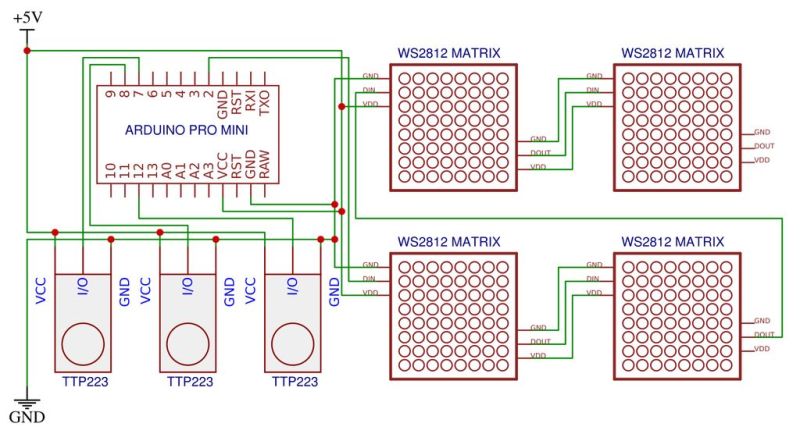
This take by [andrei.erdei] on this decades-old concept involves an ATmega328p-based Arduino Pro Mini board, a nice wooden frame, and 4 WS2812-based 65×65 mm RGB 8×8 LED matrices, as well as some TTP223 touch sensors that allow one to control the on-board cursor. This is the sole form of input: using the UP and RIGHT buttons to select the piece to move, confirm with OK, then move to the new position. The chess program will then calculate its next position and indicate it on the LED matrix.
Using physical chess pieces isn’t required either: each 4×4 grid uses a special pattern that indicates the piece that occupies it. This makes it highly portable, but perhaps not as fun as using physical pieces. It also kills the sheer joy of building up that collection of enemy pieces when you’ve hit that winning streak. You can look at the embedded gameplay video after the break and judge for yourself.
At the core of the chess program is [H.G. Muller]’s micro-Max project. Originally ported to the Arduino Uno, this program outputs the game to the serial port. After tweaking it to use the LED matrix instead, [andrei.erdei] was then faced with the lack of memory on the board for the most common LED libraries. In the end, the FAB_LED library managed to perform the task with less memory, allowing it and the rest of the program to fit comfortably into the glorious 2 kB of SRAM that the ATmega328p provides.
Classic 8-bit chess engines are marvels of software engineering. Ever wonder how they stack up against modern chess software? Check out this article!
Ah, the joys of domestic animals. Often adorable, occasionally useful, they’re universally unable to care for themselves in the slightest. That’s part of the bargain though; we take over responsibility for their upkeep and they repay us with whatever it is they do best. Unless the animal in question is a cat, of course – they have their own terms and conditions.
Chickens, though, are very useful indeed. Give them food and water and they give you delicious, nutritious, high-quality protein. Feeding them every day can be a chore, though, unless you automate the task. This Twitch-enabled robotic chicken feeder may be overkill for that simple use case, but as [Sean Hodgins] tell it, there’s a method to all the hardware he threw at this build. That would include a custom-welded steel frame holding a solar panel and batteries, a huge LED matrix display, a Raspberry Pi and camera, and of course, food dispensers. Those are of the kind once used to dispense candy or gum for a coin or two in the grocery; retooled with 3D-printed parts, the dispensers now eject a small scoop of feed whenever someone watching a Twitch stream decides to donate to the farm that’s hosting the system. You can see the build below in detail, or just pop over to Sweet Farm to check out the live feed and gawk at some chickens.
It’s an impressive bit of work on [Sean]’s part for sure, and we did notice how he used his HCC rapid prototyping module to speed up development. Still, we’re not convinced there will be many donations at $10 a pop. Then again, dropping donations to the micropayment level may lead to overfed chickens, and that’s not a good thing.
A few weeks ago, we announced that Arduino now works with TinyGo, the popular compiler that brings the Go programming language to microcontrollers. We had the opportunity to sit down with Ron Evans, Technologist for Hire, and learn more about the Arduino and TinyGo integration.
Some of our audience knows about Go (we ourselves use it to develop many of our tools). In a few words: what is TinyGo and how does it stand compared to Go itself?
TinyGo is a Go compiler for small places like microcontrollers. TinyGo is written in Go like the standard Go compiler, but TinyGo then uses the LLVM toolchain to compile Go programs to a fraction of their normal size. TinyGo also employs a different runtime implementation in order to target constrained environments.
Why choosing TinyGo over other languages?
If software is eating the world, then Go is eating the world of software. The popularity of Go is still rapidly expanding, and TinyGo helps bring the new “enterprise standard” language down to the smallest of processors. Also as a compiled language, TinyGo can offer substantially better performance and size efficiency than that of interpreted languages like JavaScript and Python.
How does TinyGo compare to embedded python and JavaScript implementations?
One good reason to use Go is the clear and maintainable code that Go insists that you create. Generally speaking, the normal Go tooling that is included with the language itself is what you use when writing TinyGo code. For example, the standard built-in code formatting. TinyGo includes implementations of the Go “net” package targeting the Arduino Nano33 IoT, so you can more easily reuse existing Go code for TCP/UDP or higher level protocols such as MQTT. This really makes it a lot easier to build commercial or industrial IoT solutions.
Another reason to use TinyGo is the ability to utilize Go’s concurrency. TinyGo implements “goroutines” which can greatly simplify your code to take the greatest performance advantage offered by modern 32-bit microcontrollers.
With security in IoT being one of today’s hottest topics, which tools does TinyGo offer that enable the development of secure projects?
There are a number of things that can make development, deployment, and operations using TinyGo good for edge computing applications that require greater security. Since the code is compiled to binary, it is possible to use code signing and other well known approaches for secure computing.
Another is that any device data must be encrypted while in transit from from the device to any cloud storage or analytics. TinyGo on the Arduino Nano33 IoT can use standard APIs for SSL communication to cloud services, such as using the Eclipse Foundation’s Paho MQTT client for Go. This makes it a lot easier for developers to do the right thing the first time when creating applications.
How can TinyGo improve the Arduino ecosystem? How will our existing audience benefit from using it? Will they be able to use the Arduino libraries already existing?
There is a very active community in the Arduino world, with lots of existing useful libraries. We are planning much deeper integration for TinyGo powered by Arduino, more on this in the near future…
Many people love TinyGo because it’s simple yet powerful. Do you see any similarity with the Arduino mission of ‘making technology simple for everybody?'”
Arduino has really pioneered the open hardware movement, and defining clear APIs to devices has been a huge contribution. TinyGo very much tries to embody this same spirit, while at the same time provide an idiomatic Go language programming experience. Combine the sensibilities that have made TinyGo so popular and that are fueling our continuing growth, alongside the amazing capabilities powered by Arduino, and there are no limits to what we can do!
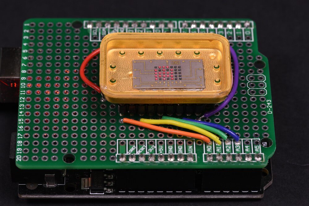
Patrick Hickey has been collecting retro LED indicators and displays for decades, and his rarest item is an HP 5082-7002—a 5×7 dot matrix LED display in a beautiful gold and (possibly) sapphire enclosure. This device is so rare, in fact, that he believes it to be a prototype, somehow relegated to eBay for gold salvage.
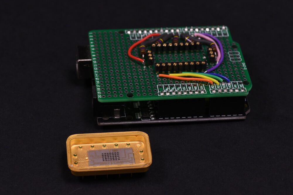
Hickey wasn’t able to find any reference to the unit—much less a datasheet—even after extensive research. Instead, he went to work reverse engineering the HP 5082-7002 following the tracks of the PCB to work out how the rows and columns are connected.
He then designed a test shield for an Arduino Uno with sockets on which the mystery device could sit. With this piece of hardware built, he can now create simple pictures and animated sprites on it using pulsed Arduino outputs.
I followed the tracks to work out which pins are connected rows and columns, and set out to build a test shield for an Arduino Uno. I decided to drive them as “rows” of 5. The max output of Arduino I/O pins is rated at 40mA, so in theory, I could simultaneously power up to 5 LEDs in parallel at 8mA using 1 pin. In practice, using strobe/multiplexing, the duty cycle is much less: 1/7 or 1/5 depending if you drive by rows (7) or columns (5) respectively. The 5 current limiting series resistors are 470 Ohms (¼ Watt). My preference is to use carbon composition resistors (e.g. Allen Bradley). I love the “retro look” of them and I think they compliment the vintage LEDs.
I had already written Arduino code for testing some TIL-305 matrix displays, so it was relatively simple to transpose the pins in my sketch for this configuration. The test code permits animations of up to 150 different alphanumeric characters/symbols, and (of course) some animated sprites inspired by retro video games.
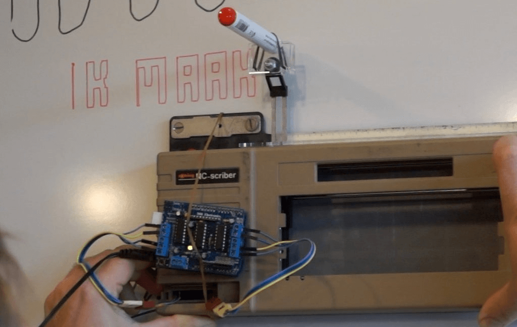
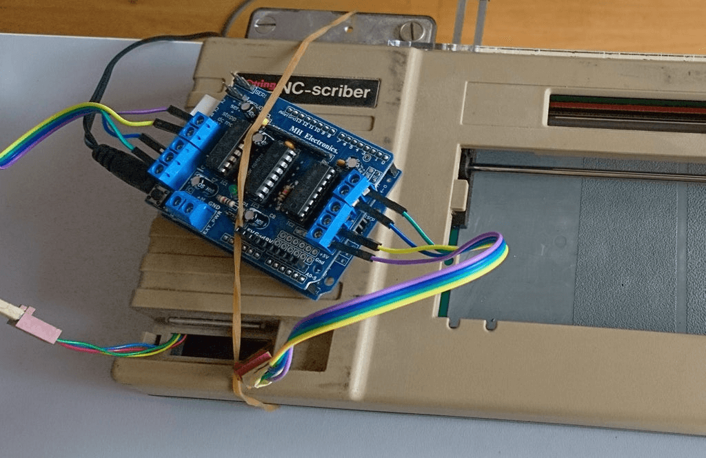
Writing on a whiteboard isn’t an easy task for many people, including instructor ‘Kenyer,’ whose lettering can be on display for a semester or more. Rather than accept his imperfect penmanship, he modified a 1980s-era Rotring NC-Scriber—originally meant for mechanical drawing use—to do this for him.
His project runs on an Arduino Uno and motor shield, along with custom mount for erasable markers. Phrases are programmed via the setup section of the sketch, but he hopes to implement the device’s keyboard for control with the help of a different motor driver in the future.
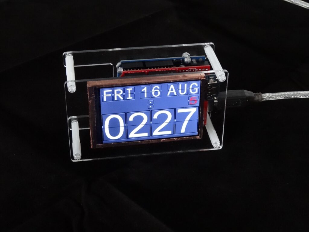
Although flip clocks may be extremely interesting electromechanical devices, with rolling flaps to show what time it is, they’re also fairly complicated if you want to build one yourself. Mark Wilson, however, took a different approach with his project, simulating the output on a 320×240 LCD display.
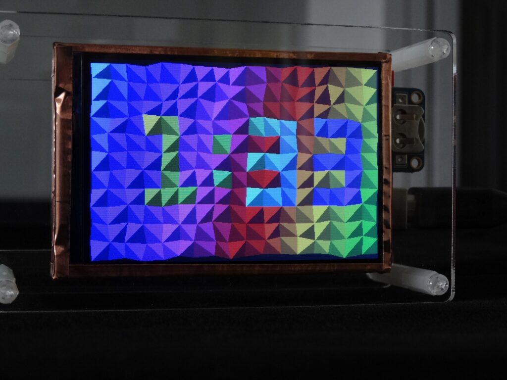
The clock is powered by an Arduino Uno and a DS3231 RTC module, allowing it to show the time, date, a blinking colon, and even the days until the trash/recycling needs to be put out. Alternate screens are available as well, including a Pong clock, triangle clock, and cube clock, which can be individually selected or set to randomly cycle if you so desire.
For its housing, Wilson chose a minimal acrylic/standoff design that seems to suit it well, and you can see it in action in the short demo clip below.
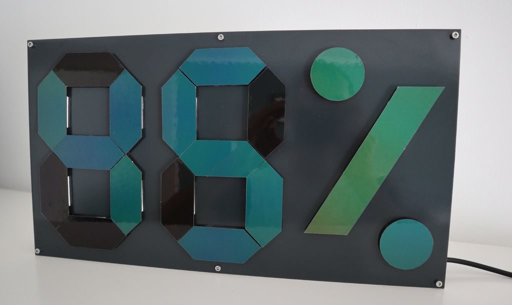
Instead of controlling his temperature and humidity display directly, maker Zaphunk did things a bit differently, driving the temperature of each segment with a Peltier element, or thermo-electric cooler (TEC), to change its color.
Each segment is made out of a thermochromic material, cycling from a black off state to a greenish hue when on, for a device that can—somewhat ironically—show the temperature by changing its temperature.
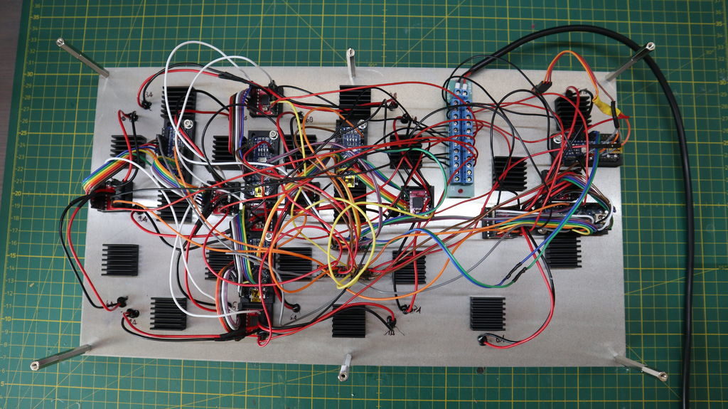
Ambient conditions are read via a DHT22 sensor, and everything is controlled by a half-dozen Arduino Nanos. This number boards were needed in order to power the nine dual motor drivers that handle the Peltier elements, each of which require two PWM outputs, along with 5 IO pins.
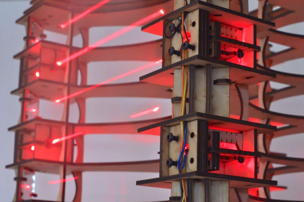
Apparently not content with a traditional laser harp, Jonathan Bumstead set out to take things in a different direction. What he came up with is a device whose laser strings are arranged horizontally, and loop though its boxy structure for an amazing audiovisual effect.
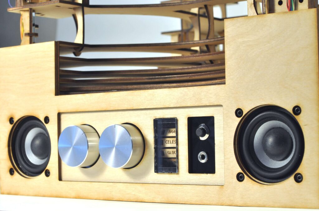
The aptly named Upright Laser Harp is divided up into six rows, which each contain two laser/photoresistor pairs for an instrument total of 12 notes. Each laser is reflected once before hitting its photoresistor to wrap the entire structure in light, and values are sensed by an Arduino Mega as note inputs. Sounds are then generated by an Adafruit Music Maker Shield, and different MIDI instruments are selected with a rotary switch and a stepper-based electromechanical display system.
Laser harps are musical devices with laser beam “strings.” When the beam is blocked, a note is played by the instrument. Usually laser harps have the beams travel vertically in the shape of a fan or vertical lines.
In this project, I built a laser harp with stacked laser beams that propagate horizontally. The beams reflect off mirrors to form square shaped beam paths. Instead of a MIDI output like my previous laser harp, this device has built-in MIDI player so the output is an audio signal. This means the device does not have to be connected to a computer or MIDI player (e.g. keyboard) to play sound. Both built-in speakers and audio output jack are available for playing music.
Be sure to check out the mini-concert and build details in the video below!
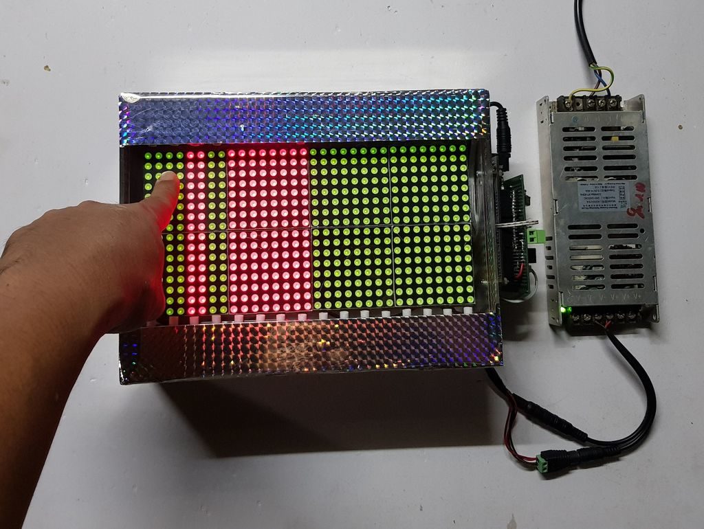
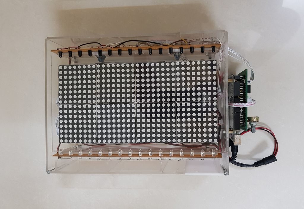
The setup uses 16 pairs of IR emitter and receivers arranged down the length of the bi-color 16×32 matrix to tell when one has inserted a finger or other object into an area. When sensed, it changes the corresponding column on the display from red to green or back again.
An Arduino Mega is used for overall control of the device, along with shift registers and multiplexers/demultiplexers to account for the massive amount of IO needed.
Code for the build is available on GitHub, and you can see it demonstrated in the video below.