Posts with «electronics» label

Old Kit Review – Diesel Sound Simulator for Model Railroads

Introduction

In this review of an older kit (circa 1993~1997) we examine the Diesel Sound Simulator for Model Railroads kit from (the now defunct) Dick Smith Electronics, based on the article published in the December 1992 issue of Silicon Chip magazine.

The purpose of this kit is to give you a small circuit which can fit in a HO scale (or larger) locomotive, or hidden underneath the layout – that can emulate the rumbling of a diesel-electric locomotive to increase the realism of a train. However the kit is designed for use with a PWM train controller (also devised by Silicon Chip!) so not for the simple direct-DC drive layouts.

Assembly

The diesel sound kit was from the time when DSE still cared about kits, so you received the sixteen page “Guide to Kit Construction” plus the kit instructions, nasty red disclaimer sheet, feedback card, plus all the required components and the obligatory coil of solder that was usually rubbish:

Everything required to get going is included, except IC sockets. My theory is it’s cheaper to use your own sockets than source older CMOS/TTL later on if you want to reuse the ICs, so sockets are now mandatory here:

The PCB is from the old school of “figure-it-out-yourself”, no fancy silk-screening here:

Notice the five horizontal pads between the two ICs – these were for wire bridges in case you needed to break the PCB in two to fit inside your locomotive.

Actual assembly was straight-forward, all the components went in without any issues. Having two links under IC2 was a little annoying, however a short while later the PCB was finished and the speaker attached:

How it works

As mentioned earlier this diesel sound kit was designed for use with the Silicon Chip train PWM controller, so the design is a little different than expected. It can handle a voltage of around 20 V, and the sound is determined by the speed of the locomotive.

The speed is determined by the back EMF measured from the motor – and (from the manual) this is the voltage produced by the motor which opposes the current flow through it and this voltage is directly proportional to speed.

Not having a 20V DC PWM supply laying about I knocked up an Arduino to PWM a 20V DC supply via an N-MOSFET module and experimented with the duty cycle to see what sort of noises could be possible. The output was affected somewhat by the supply voltage, however seemed a little higher in pitch than expected.

You can listen to the results in the following video:

I reckon the sound from around the twenty second mark isn’t a bad idle noise, however in general not that great. The results will ultimately be a function of a lower duty-cycle than I could create at the time and the values of R1 and R2 used in the kit.

 Conclusion

Another kit review over. With some time spent experimenting you could generate the required diesel sounds, a Paxman-Valenta it isn’t… but it was a fun kit and I’m sure it was well-received at the time. To those who have been asking me privately, no I don’t have a secret line to some underground warehouse of old kits – just keep an eye out on ebay and they pop up now and again. Full-sized images and much more information about the kit are available on flickr.

And while you’re here – are you interested in Arduino? Check out my new book “Arduino Workshop” from No Starch Press.

In the meanwhile have fun and keep checking into tronixstuff.com. Why not follow things on twitter, Google+, subscribe  for email updates or RSS using the links on the right-hand column? And join our friendly Google Group – dedicated to the projects and related items on this website. Sign up – it’s free, helpful to each other –  and we can all learn something.

The post Old Kit Review – Diesel Sound Simulator for Model Railroads appeared first on tronixstuff.

Tronixstuff 10 Nov 08:12

Tutorial – LM3914 Dot/Bar Display Driver IC

Introduction

This is the first of three tutorials that will examine the LM391x series of LED driver ICs. In this first tutorial we cover the LM3914, then the LM3915 and LM3916 will follow. The goal of these tutorials is to have you using the parts in a small amount of time and experiment with your driver ICs, from which point you can research further into their theory and application.

Although these parts have been around for many years, the LM3914 in particular is still quite popular. It offers a simple way to display a linear voltage level using one or more groups of ten LEDs with a minimum of fuss.

With a variety of external parts or circuitry these LEDs can then represent all sorts of data, or just blink for your amusement. We’ll run through a few example circuits that you can use in your own projects and hopefully give you some ideas for the future. Originally by National Semiconductor, the LM391X series is now handled by Texas Instruments.

Getting Started

You will need the LM3914 data sheet, so please download that and keep it as a reference. So – back to basics. The LM3914 controls ten LEDs. It controls the current through the LEDs with the use of only one resistor, and the LEDs can appear in a bar graph or single ‘dot’ when in use. The LM3914 contains a ten-stage voltage divider, each stage when reached will illuminate the matching LED (and those below it in level meter mode).

Let’s consider the most basic of examples (from page two of the data sheet) – a voltmeter with a range of 0~5V:


The Vled rail is also connected to the supply voltage in our example. Pin 9 controls the bar/dot display mode – with it connected to pin 3 the LEDs will operate in bar graph mode, leave it open for dot mode. The 2.2uF capacitor is required only when “leads to the LED supply are 6″ or longer”. We’ve hooked up the circuit above, and created a 0~5V DC source via a 10kΩ potentiometer with a multimeter to show the voltage – in the following video you can see the results of this circuit in action, in both dot and bar graph mode:

Customising the upper range and LED current

Well that was exciting, however what if you want a different reference voltage? That is you want your display to have a range of 0~3 V DC? And how do you control the current flow through each LED? With maths and resistors. Consider the following formulae:

As you can see the LED current (Iled) is simple, our example is 12.5/1210 which returned 10.3 mA – and in real life 12.7 mA (resistor tolerance is going to affect the value of the calculations).

Now to calculate a new Ref Out voltage – for example  we’ll shoot for a 3 V meter, and keep the same current for the LEDs. This requires solving for R2 in the equation above, which results with R2 = -R1 + 0.8R1V. Substituting the values – R2 = -1210 + 0.8 x 1210 x 3 gives a value of 1694Ω for R2. Not everyone will have the E48 resistor range, so try and get something as close as possible. We found a 1.8 kΩ for R2 and show the results in the following video:

You can of course have larger display range values, but a supply voltage of no more than 25 V will need to be equal to or greater than that value. E.g. if you want a 0~10 V display, the supply voltage must be >= 10V DC.

Creating custom ranges

Now we’ll look at how to create  a lower range limit, so you can have displays that (for example) can range from a non-zero positive value. For example, you want to display levels between 3 and 5V DC. From the previous section, you know how to set the upper limit, and setting the lower limit is simple – just apply the lower voltage to pin 4 (Rlo).

You can derive this using a resistor divider or other form of supply with a common GND. When creating such circuits, remember that the tolerance of the resistors used in the voltage dividers will have an affect on the accuracy. Some may wish to fit trimpots, which after alignment can be set permanently with a blob of glue.

Finally, for more reading on this topic – download and review the TI application note.

Chaining multiple LM3914s

Two or more LM3914s can be chained together to increase the number of LEDs used to display the levels over an expanded range. The circuitry is similar to using two independent units, except the REFout (pin 7) from the first LM3914 is fed to the REFlo (pin 4) of the second LM3914 – whose REFout is set as required for the upper range limit. Consider the following example schematic which gave a real-world range of 0~3.8V DC:

The 20~22kΩ resistor is required if you’re using dot mode (see “Dot mode carry” in page ten of the data sheet). Moving on, the circuit above results with the following:

Where to from here?

Now you can visually represent all sorts of low voltages for many purposes. There’s more example circuits and notes in the LM3914 data sheet, so have a read through and delve deeper into the operation of the LM3914. Furthermore Dave Jones from eevblog.com has made a great video whcih describes a practical application of the LM3914:

Conclusion

As always I hope you found this useful. Don’t forget to stay tuned for the second and third instalments using the LM3915 and LM3916. Full-sized images are on flickr. And if you made it this far – check out my new book “Arduino Workshop” from No Starch Press.

In the meanwhile have fun and keep checking into tronixstuff.com. Why not follow things on twitter, Google+, subscribe  for email updates or RSS using the links on the right-hand column? And join our friendly Google Group – dedicated to the projects and related items on this website. Sign up – it’s free, helpful to each other –  and we can all learn something.

The post Tutorial – LM3914 Dot/Bar Display Driver IC appeared first on tronixstuff.

Tronixstuff 13 Sep 15:13
bar  display  dot  driver  electronics  example  ic  led  level  lm3914  lm3915  lm3916  ti  tronixstuff  tutorial  voltmeter  

Australian Electronics Nostalgia – Talking Electronics Kits

Introduction

From 1981, Australian electrical engineer Colin Mitchell started publishing his home-grown electronics magazine “Talking Electronics”. His goal was to get people interested and learning about electronics, and more so with a focus on digital electronics. It was (and still is) a lofty goal – in which he succeeded. From a couple of rooms in his home the magazine flourished, and many projects described within were sold as kits. At one stage there were over 150 Talking Electronics kits on the market. You could find the books and kits in retail outlets such as Dick Smith Electronics, and for a short while there was a TE store in Moorabbin (Victoria). Colin and the team’s style of writing was easy to read and very understandable – but don’t take my word for it, you can download the magazines from his website (they’re near the bottom of the left column). Dave Jones recently interviewed Colin, and you can watch those for much more background information.

Over fifteen issues you could learn about blinking LEDs all the way to making your own expandable Z80 board computer, and some of the kits may still be available. Colin also published a series of tutorial books on electronics, and also single-magazine projects. And thus the subjects of our review … we came across the first of these single-issue projects from 1981 – the Mini Frequency Counter (then afterwards we have another kit):

How great is that? The PCB comes with the magazine. This is what set TE apart from the rest, and helped people learn by actually making it easy to build what was described in the magazine instead of just reading about it. For 1981 the PCB was quite good – they were silk-screened which was quite rare at the time:

And if you weren’t quite ready, the magazine also included details of a square-wave oscillator to make and a 52-page short course in digital electronics. However back to the kit…

Assembly

The kit uses common parts and I hoard CMOS ICs so building wasn’t a problem. This (original) version of the kit used LEDs instead of 7-segment displays (which were expensive at the time) so there was plenty of  careful soldering to do:

And after a while the counter started to come together. I used IC sockets just in case:

The rest was straight-forward, and before long 9 V was supplied, and we found success:

To be honest progress floundered for about an hour at this point – the display wouldn’t budge off zero. After checking the multi-vibrator output, calibrating the RC circuits and finally tracing out the circuit with a continuity tester, it turned out one of the links just wasn’t soldered in far enough – and the IC socket for the 4047 was broken So a new link and directly fitting the 4047 fixed it. You live and learn.

Operation

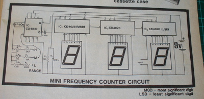
So – we now have a frequency counter that’s good for 100 Hz to the megahertz range, with a minimum of parts. Younger, non-microcontroller people may wonder how that is possible – so here’s the schematic:

The counter works by using a multi-vibrator using a CD4047 to generate a square-wave at 50, 500 and 5 kHz, and the three trimpots are adjusted to calibrate the output. The incoming pulses to measure are fed to the 4026 decade counter/divider ICs. Three of these operate in tandem and each divide the incoming count by ten – and display or reset by the alternating signal from the 4047. However for larger frequencies (above 900 Hz) you need to change the frequency fed to the display circuit in order to display the higher (left-most) digits of the result. A jumper wire is used to select the required level (however if you mounted the kit in a case, a knob or switch could be used).

For example, if you’re measuring 3.456 MHz you start with the jumper on H and the display reads 345 – then you switch to M to read 456 – then you switch to the L jumper and read 560, giving you 3456000 Hz. If desired, you can extend the kit with another PCB to create a 5-digit display. The counter won’t be winning any precision contests – however it has two purposes, which are fulfilled very well. It gives the reader an inexpensive piece of test equipment that works reasonably well, and a fully-documented project so the reader can understand how it works (and more).

And for the curious –  here it is in action:

[Update 20/07/2013] Siren Kit

Found another kit last week, the Talking Electronics “DIY Kit #31 – 9V siren”. It’s an effective and loud siren with true rise and fall, unlike other kits of the era that alternated between two fixed tones. The packaging was quite strong and idea for mail-order at the time:

The label sells the product (and shows the age):

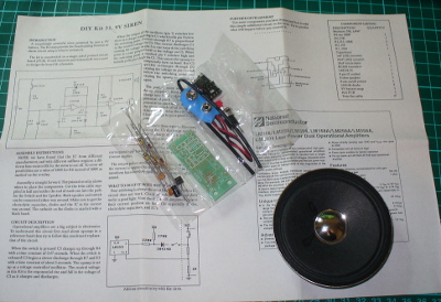
The kit included every part required to work, apart from a PP3 battery, and a single instruction sheet with a good explanation of how the circuit works, and some data about the LM358:

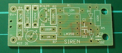
… and as usual the PCB was ahead of its’ time with full silk-screen and solder mask:

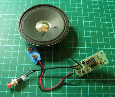
Assembly was quite straight-forward. The design is quite compact, so a lot of vertical resistor mounting was necessary due to the lack of space. However it was refreshing to not have any links to fit. After around twenty minutes of relaxed construction, it was ready to test:

It’s a 1/2 watt speaker, however much louder than originally anticipated:

Once again, another complete and well-produced kit.

Conclusion

That was a lot of fun, and I’m off to make the matching square-wave oscillator for the frequency counter. Kudos to Colin for all those years of publication and helping people learn. Lots of companies bang on about offering tutorials and information on the Internet for free, but Colin has been doing it for over ten years. Check out his Talking Electronics website for a huge variety of knowledge, an excellent electronics course you can get on CD – and go easy on him if you have any questions.

Full-sized images available on flickr. This kit was purchased without notifying the supplier.

And if you made it this far – check out my new book “Arduino Workshop” from No Starch Press.

In the meanwhile have fun and keep checking into tronixstuff.com. Why not follow things on twitter, Google+, subscribe  for email updates or RSS using the links on the right-hand column? And join our friendly Google Group – dedicated to the projects and related items on this website. Sign up – it’s free, helpful to each other –  and we can all learn something.

The post Australian Electronics Nostalgia – Talking Electronics Kits appeared first on tronixstuff.

Tutorial – Arduino and PCF8591 ADC DAC IC

Learn how to use the NXP PCF 8591 8-bit A/D and D/A IC with Arduino in chapter fifty-two of my Arduino Tutorials. The first chapter is here, the complete series is detailed here.

Updated 17/06/2013

Introduction

Have you ever wanted more analogue input pins on your Arduino project, but not wanted to fork out for a Mega? Or would you like to generate analogue signals? Then check out the subject of our tutorial – the NXP PCF8591 IC. It solves both these problems as it has a single DAC (digital to analogue) converter as well as four ADCs (analogue to digital converters) – all accessible via the I2C bus. If the I2C bus is new to you, please familiarise yourself with the readings here before moving forward.

The PCF8591 is available in DIP form, which makes it easy to experiment with:
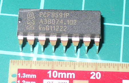
You can get them from the usual retailers. Before moving on, download the data sheet. The PCF8591 can operate on both 5V and 3.3V so if you’re using an Arduino Due, Raspberry Pi or other 3.3 V development board you’re fine. Now we’ll first explain the DAC, then the ADCs.

Using the DAC (digital-to-analogue converter)

The DAC on the PCF8591 has a resolution of 8-bits – so it can generate a theoretical signal of between zero volts and the reference voltage (Vref) in 255 steps. For demonstration purposes we’ll use a Vref of 5V, and you can use a lower Vref such as 3.3V or whatever you wish the maximum value to be … however it must be less than the supply voltage. Note that when there is a load on the analogue output (a real-world situation), the maximum output voltage will drop – the data sheet (which you downloaded) shows a 10% drop for a 10kΩ load. Now for our demonstration circuit:
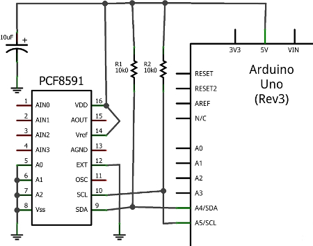
Note the use of 10kΩ pull-up resistors on the I2C bus, and the 10μF capacitor between 5V and GND. The I2C bus address is set by a combination of pins A0~A2, and with them all to GND the address is 0x90. The analogue output can be taken from pin 15 (and there’s a seperate analogue GND on pin 13. Also, connect pin 13 to GND, and circuit GND to Arduino GND.

To control the DAC we need to send two bytes of data. The first is the control byte, which simply activates the DAC and is 1000000 (or 0x40) and the next byte is the value between 0 and 255 (the output level). This is demonstrated in the following sketch:

// Example 52.1 PCF8591 DAC demo
// http://tronixstuff.com/tutorials Chapter 52
// John Boxall June 2013
#include "Wire.h"
#define PCF8591 (0x90 >> 1) // I2C bus address
void setup()
{
 Wire.begin();
}
void loop()
{
 for (int i=0; i<256; i++)
 {
 Wire.beginTransmission(PCF8591); // wake up PCF8591
 Wire.write(0x40); // control byte - turn on DAC (binary 1000000)
 Wire.write(i); // value to send to DAC
 Wire.endTransmission(); // end tranmission
 }

 for (int i=255; i>=0; --i)
 {
 Wire.beginTransmission(PCF8591); // wake up PCF8591
 Wire.write(0x40); // control byte - turn on DAC (binary 1000000)
 Wire.write(i); // value to send to DAC
 Wire.endTransmission(); // end tranmission
 }
}

Did you notice the bit shift of the bus address in the #define statement? Arduino sends 7-bit addresses but the PCF8591 wants an 8-bit, so we shift the byte over by one bit. 

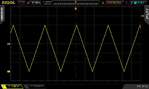
The results of the sketch are shown below, we’ve connected the Vref to 5V and the oscilloscope probe and GND to the analogue output and GND respectively:
If you like curves you can generate sine waves with the sketch below. It uses a lookup table in an array which contains the necessary pre-calculated data points:

// Example 52.2 PCF8591 DAC demo - sine wave
// http://tronixstuff.com/tutorials Chapter 52
// John Boxall June 2013

#include "Wire.h"
#define PCF8591 (0x90 >> 1) // I2C bus address

uint8_t sine_wave[256] = {
 0x80, 0x83, 0x86, 0x89, 0x8C, 0x90, 0x93, 0x96,
 0x99, 0x9C, 0x9F, 0xA2, 0xA5, 0xA8, 0xAB, 0xAE,
 0xB1, 0xB3, 0xB6, 0xB9, 0xBC, 0xBF, 0xC1, 0xC4,
 0xC7, 0xC9, 0xCC, 0xCE, 0xD1, 0xD3, 0xD5, 0xD8,
 0xDA, 0xDC, 0xDE, 0xE0, 0xE2, 0xE4, 0xE6, 0xE8,
 0xEA, 0xEB, 0xED, 0xEF, 0xF0, 0xF1, 0xF3, 0xF4,
 0xF5, 0xF6, 0xF8, 0xF9, 0xFA, 0xFA, 0xFB, 0xFC,
 0xFD, 0xFD, 0xFE, 0xFE, 0xFE, 0xFF, 0xFF, 0xFF,
 0xFF, 0xFF, 0xFF, 0xFF, 0xFE, 0xFE, 0xFE, 0xFD,
 0xFD, 0xFC, 0xFB, 0xFA, 0xFA, 0xF9, 0xF8, 0xF6,
 0xF5, 0xF4, 0xF3, 0xF1, 0xF0, 0xEF, 0xED, 0xEB,
 0xEA, 0xE8, 0xE6, 0xE4, 0xE2, 0xE0, 0xDE, 0xDC,
 0xDA, 0xD8, 0xD5, 0xD3, 0xD1, 0xCE, 0xCC, 0xC9,
 0xC7, 0xC4, 0xC1, 0xBF, 0xBC, 0xB9, 0xB6, 0xB3,
 0xB1, 0xAE, 0xAB, 0xA8, 0xA5, 0xA2, 0x9F, 0x9C,
 0x99, 0x96, 0x93, 0x90, 0x8C, 0x89, 0x86, 0x83,
 0x80, 0x7D, 0x7A, 0x77, 0x74, 0x70, 0x6D, 0x6A,
 0x67, 0x64, 0x61, 0x5E, 0x5B, 0x58, 0x55, 0x52,
 0x4F, 0x4D, 0x4A, 0x47, 0x44, 0x41, 0x3F, 0x3C,
 0x39, 0x37, 0x34, 0x32, 0x2F, 0x2D, 0x2B, 0x28,
 0x26, 0x24, 0x22, 0x20, 0x1E, 0x1C, 0x1A, 0x18,
 0x16, 0x15, 0x13, 0x11, 0x10, 0x0F, 0x0D, 0x0C,
 0x0B, 0x0A, 0x08, 0x07, 0x06, 0x06, 0x05, 0x04,
 0x03, 0x03, 0x02, 0x02, 0x02, 0x01, 0x01, 0x01,
 0x01, 0x01, 0x01, 0x01, 0x02, 0x02, 0x02, 0x03,
 0x03, 0x04, 0x05, 0x06, 0x06, 0x07, 0x08, 0x0A,
 0x0B, 0x0C, 0x0D, 0x0F, 0x10, 0x11, 0x13, 0x15,
 0x16, 0x18, 0x1A, 0x1C, 0x1E, 0x20, 0x22, 0x24,
 0x26, 0x28, 0x2B, 0x2D, 0x2F, 0x32, 0x34, 0x37,
 0x39, 0x3C, 0x3F, 0x41, 0x44, 0x47, 0x4A, 0x4D,
 0x4F, 0x52, 0x55, 0x58, 0x5B, 0x5E, 0x61, 0x64,
 0x67, 0x6A, 0x6D, 0x70, 0x74, 0x77, 0x7A, 0x7D
};
void setup()
{
 Wire.begin();
}
void loop()
{
 for (int i=0; i<256; i++)
 {
 Wire.beginTransmission(PCF8591); // wake up PCF8591
 Wire.write(0x40); // control byte - turn on DAC (binary 1000000)
 Wire.write(sine_wave[i]); // value to send to DAC
 Wire.endTransmission(); // end tranmission
 }
}

And the results:
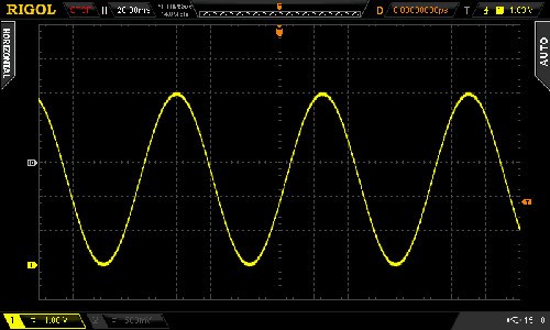
For the following DSO image dump, we changed the Vref to 3.3V – note the change in the maxima on the sine wave:
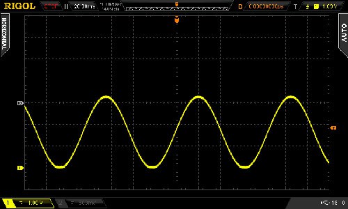
Now you can experiment with the DAC to make sound effects, signals or control other analogue circuits.

Using the ADCs (analogue-to-digital converters)

If you’ve used the analogRead() function on your Arduino (way back in Chapter One) then you’re already familiar with an ADC. With out PCF8591 we can read a voltage between zero and the Vref and it will return a value of between zero and 255 which is directly proportional to zero and the Vref. For example, measuring 3.3V should return 168. The resolution (8-bit) of the ADC is lower than the onboard Arduino (10-bit) however the PCF8591 can do something the Arduino’s ADC cannot. But we’ll get to that in a moment.

First, to simply read the values of each ADC pin we send a control byte to tell the PCF8591 which ADC we want to read. For ADCs zero to three the control byte is 0x00, 0x01, ox02 and 0x03 respectively. Then we ask for two bytes of data back from the ADC, and store the second byte for use. Why two bytes? The PCF8591 returns the previously measured value first – then the current byte. (See Figure 8 in the data sheet). Finally, if you’re not using all the ADC pins, connect the unused ones to GND.

The following example sketch simply retrieves values from each ADC pin one at a time, then displays them in the serial monitor:

// Example 52.3 PCF8591 ADC demo
// http://tronixstuff.com/tutorials Chapter 52
// John Boxall June 2013
#include "Wire.h"
#define PCF8591 (0x90 >> 1) // I2C bus address
#define ADC0 0x00 // control bytes for reading individual ADCs
#define ADC1 0x01
#define ADC2 0x02
#define ADC3 0x03
byte value0, value1, value2, value3;
void setup()
{
 Wire.begin();
 Serial.begin(9600);
}
void loop()
{
 Wire.beginTransmission(PCF8591); // wake up PCF8591
 Wire.write(ADC0); // control byte - read ADC0
 Wire.endTransmission(); // end tranmission
 Wire.requestFrom(PCF8591, 2);
 value0=Wire.read();
 value0=Wire.read();
 Wire.beginTransmission(PCF8591); // wake up PCF8591
 Wire.write(ADC1); // control byte - read ADC1
 Wire.endTransmission(); // end tranmission
 Wire.requestFrom(PCF8591, 2);
 value1=Wire.read();
 value1=Wire.read();
 Wire.beginTransmission(PCF8591); // wake up PCF8591
 Wire.write(ADC2); // control byte - read ADC2
 Wire.endTransmission(); // end tranmission
 Wire.requestFrom(PCF8591, 2);
 value2=Wire.read();
 value2=Wire.read();
 Wire.beginTransmission(PCF8591); // wake up PCF8591
 Wire.write(ADC3); // control byte - read ADC3
 Wire.endTransmission(); // end tranmission
 Wire.requestFrom(PCF8591, 2);
 value3=Wire.read();
 value3=Wire.read();
 Serial.print(value0); Serial.print(" ");
 Serial.print(value1); Serial.print(" ");
 Serial.print(value2); Serial.print(" ");
 Serial.print(value3); Serial.print(" ");
 Serial.println();
}

Upon running the sketch you’ll be presented with the values of each ADC in the serial monitor. Although it was a simple demonstration to show you how to individually read each ADC, it is a cumbersome method of getting more than one byte at a time from a particular ADC.

To do this, change the control byte to request auto-increment, which is done by setting bit 2 of the control byte to 1. So to start from ADC0 we use a new control byte of binary 00000100 or hexadecimal 0x04. Then request five bytes of data (once again we ignore the first byte) which will cause the PCF8591 to return all values in one chain of bytes. This process is demonstrated in the following sketch:

// Example 52.4 PCF8591 ADC demo
// http://tronixstuff.com/tutorials Chapter 52
// John Boxall June 2013
#include "Wire.h"
#define PCF8591 (0x90 >> 1) // I2C bus address
byte value0, value1, value2, value3;
void setup()
{
 Wire.begin();
 Serial.begin(9600);
}
void loop()
{
 Wire.beginTransmission(PCF8591); // wake up PCF8591
 Wire.write(0x04); // control byte - read ADC0 then auto-increment
 Wire.endTransmission(); // end tranmission
 Wire.requestFrom(PCF8591, 5);
 value0=Wire.read();
 value0=Wire.read();
 value1=Wire.read();
 value2=Wire.read();
 value3=Wire.read();
 Serial.print(value0); Serial.print(" ");
 Serial.print(value1); Serial.print(" ");
 Serial.print(value2); Serial.print(" ");
 Serial.print(value3); Serial.print(" ");
 Serial.println();
}

Previously we mentioned that the PCF8591 can do something that the Arduino’s ADC cannot, and this is offer a differential ADC. As opposed to the Arduino’s single-ended (i.e. it returns the difference between the positive signal voltage and GND, the differential ADC accepts two signals (that don’t necessarily have to be referenced to ground), and returns the difference between the two signals. This can be convenient for measuring small changes in voltages for load cells and so on.

Setting up the PCF8591 for differential ADC is a simple matter of changing the control byte. If you turn to page seven of the data sheet, then consider the different types of analogue input programming. Previously we used mode ’00’ for four inputs, however you can select the others which are clearly illustrated, for example:
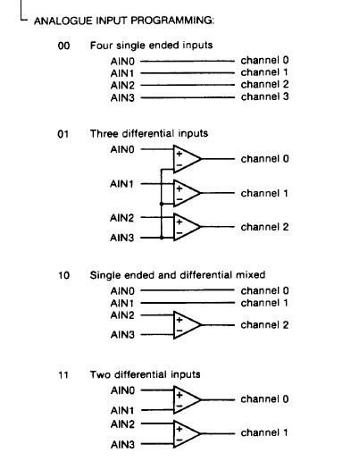
So to set the control byte for two differential inputs, use binary 00110000 or 0x30. Then it’s a simple matter of requesting the bytes of data and working with them. As you can see there’s also combination single/differential and a complex three-differential input. However we’ll leave them for the time being.

Conclusion

Hopefully you found this of interest, whether adding a DAC to your experiments or learning a bit more about ADCs. We’ll have some more analogue to digital articles coming up soon, so stay tuned. And if you enjoy my tutorials, or want to introduce someone else to the interesting world of Arduino – check out my new book “Arduino Workshop” from No Starch Press.

In the meanwhile have fun and keep checking into tronixstuff.com. Why not follow things on twitter, Google+, subscribe  for email updates or RSS using the links on the right-hand column? And join our friendly Google Group – dedicated to the projects and related items on this website. Sign up – it’s free, helpful to each other –  and we can all learn something.

The post Tutorial – Arduino and PCF8591 ADC DAC IC appeared first on tronixstuff.

Recap of #hackPHX: Arduino Hackathon @HeatSyncLabs

Friday night kicked off the #hackPHX Arduino hackathon at HeatSync Labs, the Phoenix area hackerspace. Everyone gathered to form 10 teams that included one Arduino newbie, one veteran, and one entrant with "hackerspace" skills (3D printing lasering welding sewing, whatever). They would have use of the entire hackerspace, an on-site designer from sponsor Cynergy, and whatever they could find at local hardware stores. Oh, and one more thing, they had to use our secret ingredient: The Shieldbot from SeeedStudios, developed by Colin Ho is a shield robot for Arduino that has five reflectance sensors, two DC motors and a 3.7V lion battery.

HeatSynch Labs Hosts Arduino Hackathon

Phoenix's HeatSynch Labs will host HackPHX Arduino, an all-day and all-night Arduino hackathon tomorrow, Feb. 2, from 10am-10:15pm. Here's how it will go down: In a ode to Iron Chef, 50 participants will be split into 10 teams for 12 hours to create something awesome from an Arduino, a "secret ingredient," and the hackerspace's resources. The teams will compete for more than $4,000 in prizes and giveaways. Expect music, robots, interactive light, wearable electronics, and more. Tickets are sold out but the the event will be live streamed

Read the full article on MAKE

Interview with Pinoccio Co-Founder Eric Jennings

Eric Weddington, marketing manager for open source and communities at Atmel, posted an in-depth interview with Pinoccio's Eric Jennings. Pinnoccio is a new, open source hardware company. Their first product is a microcontroller board aimed at creating “a complete ecosystem" for the internet of things. Pinoccio calls their board an "Arduino Mega with wings." It's Raspberry Pi-friendly, too.

Read the full article on MAKE

Hexy’s Back in the Maker Shed

After selling out completely over the Holidays, a new shipment of Arcbotics' Hexy the Hexipod has arrived in the Maker Shed. Hexy comes in kit form with well written documentation and tutorials which make learning complex robotics straightforward and fun!

Read the full article on MAKE

Prototype a Puppet Play

Gal Sasson is running this puppet theater project using little more than an Arduino and some control software on a computer. The puppets, theater, and control box are all handmade.

Read the full article on MAKE

MAKE » Arduino 25 Feb 21:09

People Watching with Maker and “Social Observer” Natalia Buckley

Natalia Buckley is a hacker, designer, and creative technologist. She's originally from Poland and now live in Brighton on England's south coast, a city famed for its appetite for experimentation. "I'm just making speculative things, that don't necessarily fully exist in the real world, but help us learn something," she says. "I'm a social observer. The sole reason I make things is to learn something about other people. Because I find other people fascinating. My work in technology is basically about people. People constantly interact with technology and I can make technology to watch them do stuff!"

Read the full article on MAKE

MAKE » Arduino 22 Feb 00:01