Posts with «arduino» label

2D-Scanner Records Surfboard Profiles for Posterity

[Ryan Schenk] had a problem: he built the perfect surfboard. Normally that wouldn’t present a problem, but in this case, it did because [Ryan] had no idea how he carved the gentle curves on the bottom of the board. So he built this homebrew 2D-scanner to make the job of replicating his hand-carved board a bit easier.

Dubbed the Scanbot 69420 – interpretation of the number is left as an exercise for the reader, my dude – the scanner is pretty simple. It’s just an old mouse carrying a digital dial indicator from Harbor Freight. The mouse was gutted, with even the original ball replaced by an RC plane wheel. The optical encoder and buttons were hooked to an Arduino, as was the serial output of the dial indicator. The Arduino consolidates the data from both sensors and sends a stream of X- and Z-axis coordinates up the USB cable as the rig slides across the board on a straightedge. On the PC side, a Node.js program turns the raw data into a vector drawing that represents the profile of the board at that point. Curves are captured at various points along the length of the board, resulting in a series of curves that can be used to replicate the board.

Yes, this could have been done with a straightedge, a ruler, and a pencil and paper – or perhaps with a hacked set of calipers – but that wouldn’t be nearly as much fun. And we can certainly see applications for this far beyond the surfboard shop.
Vintage vacuum fluorescent display controlled with Arduino Due

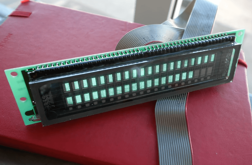
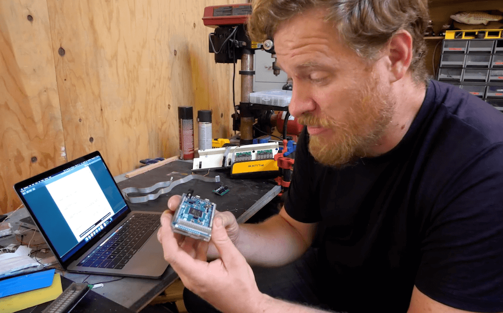
Vacuum fluorescent displays (VFDs) have a distinct cool blue-greenish glow, and were once used in a wide range of devices, from VCRs to microwave ovens and even car dashboards. Although extremely popular way back when, they can be more difficult to source today. In the video below, Scotty Allen of the Strange Parts YouTube channel takes on the challenge of getting a $600 ISE (now Noritake) display up and running with an Arduino Due.

The process starts with examining the datasheet to find that the Due’s 3.3V logic can indeed drive the 20×2 character display, then he constructs a custom adapter board to do just that. After more datasheet lurking, head scratching and hacking, he finally got it to show “Hello world!” toward the end of the clip, along with some simple animations. 

The VFD control is part of a larger build that will be revealed in the future, and a good reminder of just how much trial and error is needed to succeed in making something awesome.

Control a swarm of drones with this wearable tactile device

If you fly drones for fun—or perhaps even for work—you know that piloting them can sometimes be a difficult tasks. Imagine, however, trying to control four drones simultaneously. While also “challenging,” researchers at the Skolkovo Institute of Science and Technology in Russia have come up with a new approach for commanding such a swarm using only arm movements.

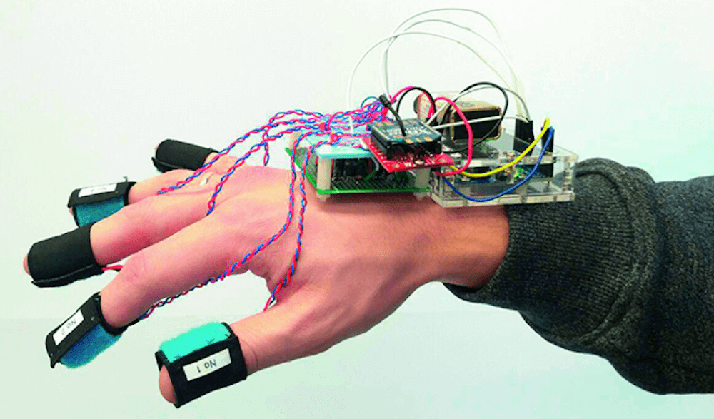
SwarmTouch takes the form of a wrist and finger-mounted device, with an array of eight cameras tracking its position. When the operator moves their arm, the drones react to the hand motion and the other flying robots in the group, as if there was a mechanical system linking each one together. 

Feedback is provided by an Arduino Uno connected to the control station via an XBee radio, which tells the operator whether the swarm is expanding or contracting using vibration motors on a wearer’s fingertips. The setup is on display in the video below and its research paper can be found here.

We propose a novel interaction strategy for a human-swarm communication when a human operator guides a formation of quadrotors with impedance control and receives vibrotactile feedback. The presented approach takes into account the human hand velocity and changes the formation shape and dynamics accordingly using impedance interlinks simulated between quadrotors, which helps to achieve a life-like swarm behavior. Experimental results with Crazyflie 2.0 quadrotor platform validate the proposed control algorithm. The tactile patterns representing dynamics of the swarm (extension or contraction) are proposed. The user feels the state of the swarm at his fingertips and receives valuable information to improve the controllability of the complex life-like formation. The user study revealed the patterns with high recognition rates. Subjects stated that tactile sensation improves the ability to guide the drone formation and makes the human-swarm communication much more interactive. The proposed technology can potentially have a strong impact on the human- swarm interaction, providing a new level of intuitiveness and immersion into the swarm navigation.

Arduino Blog 01 Oct 17:03
arduino  drones  featured  uno  xbee  

Rip current lighting system enhances water safety

Drowning is the third leading cause of accidental death in New Zealand, and the vast majority of lifeguard rescues are due to rip currents—hard to observe unless you’re already in peril. In order to help fix this problem, Victoria University of Wellington students Hannah Tilsley and Chamonix Stuart designed the “Nah Yeah Buoy” water safety system.

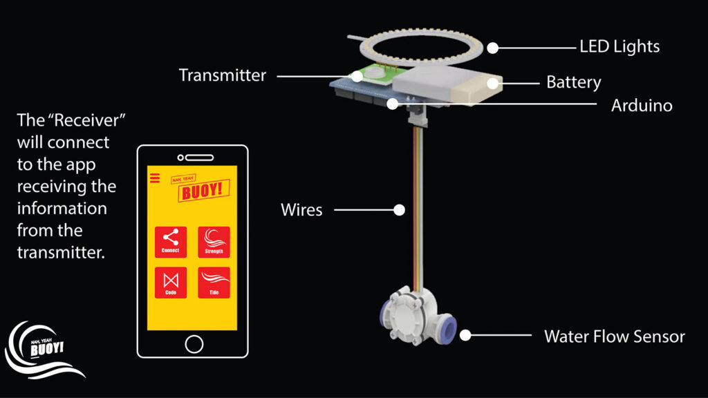
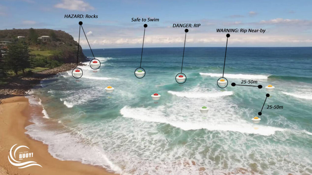
The system consists of a network of sensing buoys and a mobile app. The buoys feature a water flow sensor on their base to measure currents, and use an Arduino to control lights on the top to shine according to the water speed. Green means it’s safe to swim, yellow is for caution, and red indicates danger, in similar manner to how traffic lights. Additionally, two-way wireless communication sends alerts to lifeguards on the shore, who can override the lights to warn of danger when needed. 

As seen here, the project was named a runner-up in the 2019 New Zealand James Dyson Award.

The “Nah Yeah Buoy” is an adaptive system for water safety designed to identify rip currents near beaches, visualise their locations and movements, and provide interactive alerts and warnings for lifeguards and water users.

Our “Nah Yeah buoy” consists of a network of sensing buoys and a mobile app for lifeguards. Rip currents are characterised by a localised strong flow of water that moves away from the shore at a typical speed of 0.5 to 2.5 meters per second. Each buoy of the network has a customised fluid flow sensor at its bottom to measure the strength/speed of the water as it flows through, and the value is compared to a set of thresholds by a built-in microcontroller real time. A high-intensity light placed on top then indicates the level of danger in three colours: green for “Yeah” (good to swim); orange for an alert; and red for “Nah” (do not swim). The buoys also transmit the information wirelessly to an app on the lifeguards’ mobile devices which allows them to adjust the thresholds as needed. The buoys are lightweight, very easy to install and individually manageable and form a network automatically.

Measuring a mini steam engine’s speed with Arduino

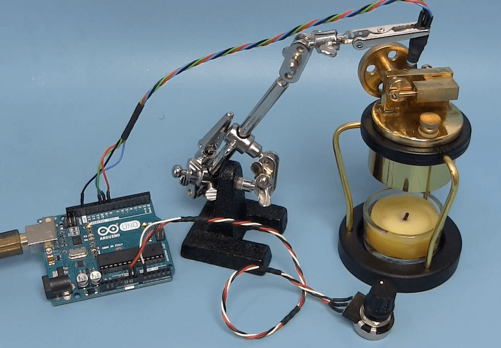
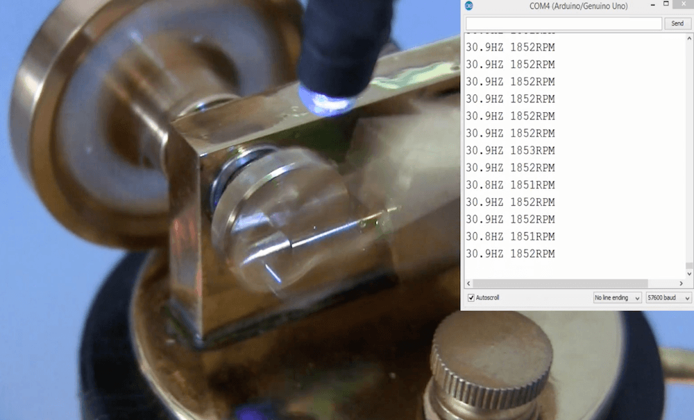
Joop Brokking has been experimenting with a miniature candle-powered steam engine. It’s an amazing little device, able to push a piston over and over to turn a flywheel, releasing the steam via a mechanically-controlled valve. But just how fast does it go?

Of course, there are a plethora of ways to determine its speed, but Brokking chose to do so using an Arduino Uno, a potentiometer and an LED that’s arranged over the piston assembly. 

The light source is programmed to pulse on and off, with a frequency that can be adjusted using the potentiometer. He then aligned this pulsing with the piston’s cyclic rate, visually “freezing” the device in time. This frequency and RPM numbers are output over the serial monitor, giving him a speed of around 1850 RPM.

Arduino Blog 30 Sep 16:08

Upgrading a MIDI Controller with an FPGA

While the “M” in MIDI stands for “musical”, it’s possible to use this standard for other things as well. [s-ol] has been working on a VJ setup (mixing video instead of music) using various potentiometer-based hardware and MIDI to interface everything together. After becoming frustrated with drift in the potentiometers, he set out to outfit the entire rig with custom-built encoders.

[s-ol] designed the rotary-encoder based boards around an FPGA. It monitors the encoder for changes, controls eight RGB LEDs per knob, and even does capacitive touch sensing on the aluminum knob itself. The FPGA communicates via SPI with an Arduino master controller which communicates to a PC using a serial interface. This is [s-ol]’s first time diving into an FPGA project and it looks like he hit it out of the park!.

Even if you’re not mixing video or music, these encoders might be useful to any project where a standard analog potentiometer isn’t accurate or precise enough, or if you just need something that can dial into a specific value quickly. Potentiometers fall short in many different ways, but if you don’t want to replace them you might modify potentiometers to suit your purposes.

Arduino Wire Bender Probably Won’t Kill All Humans

Do you want to make your own springs? Yeah, that’s what we thought. Well, blow the dust off of that spare Arduino and keep reading. A few months ago, we let you know that renowned circuit sculptor [Jiří Praus] was working on a precision wire-bending machine to help him hone his craft. Now it’s real, it’s spectacular, and it’s completely open source.

Along with that ‘duino you’ll need a CNC shield and a couple of NEMA 17 steppers — one to feed the wire and one to help bend it. Before being bent or coiled into springs, the wire must be super straight, so the wire coming off the spool holder runs through two sets of rollers before being fed into the bender.

[Jiří]’s main goal for this build was precision, which we can totally get behind. If you’re going to build a machine to do something for you, ideally, it should also do a better job than you alone. It’s his secondary goal that makes this build so extraordinary. [Jiří] wanted it to be easy to build with commonly-available hardware and a 3D printer. Every part is designed to be printed without supports. Bounce past the break to watch the build video.

You can also make your own springs on a lathe, or print them with hacked g-code.

These LEGO linkage walkers wander under Arduino control

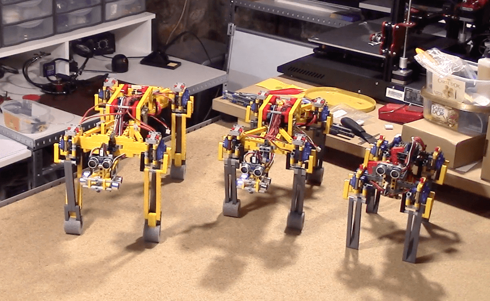
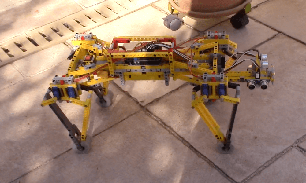
YouTuber Oracid1 has developed a unique family of four-legged robots, dubbed “FiveBarQuads.”

The quadrupeds all feature ultrasonic sensing for navigation and a body made out of LEGO components — and as seen in the first video below, his latest (and largest) version is able to navigate quite nicely on its own. It’s even able to traverse a grate and maneuver around a potted plant, though chair legs are understandably a bit tricky.

The robots use an Arduino Uno for control along with a total of 16 micro servos in its shoulders (four each) in order to move the limbs. Two servos are employed to actuate each upper linkage for the legs, which are attached to bottom sections, and finally to the feet portion through a series of joints. This allows for an interesting locomotion capability that could be applicable in a variety of situations.

Arduino Blog 27 Sep 19:04

An interactive wall map with DMX programmable lights and visual ‘narration’

Non-profits can do great work, and in order to help others visualize the needs they serve and what they are doing, Jason Wolin came up with an amazing map for his organization.

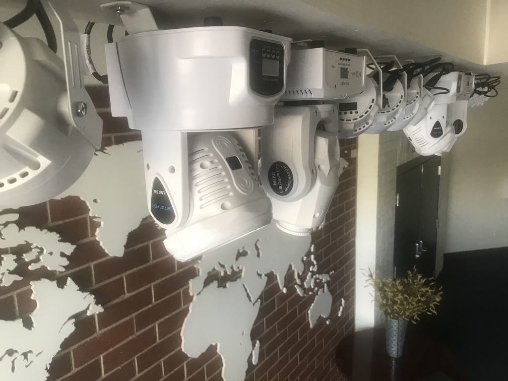
The massive map stretches down 14 feet of a brick wall, with the continents cut out of MDF, and a pair of accompanying LCD TVs that show data about different areas.

Three computers are used for control, two of which are used to play videos on each screen. The third handles overhead map lighting controlled via the DMX protocol to illuminate the map in various configurations. Each of the PCs are coordinated using a trio of Arduino Nanos, allowing video and lighting effects to be displayed in perfect sync.

Arduino Blog 26 Sep 21:14
arduino  dmx  featured  lighting  nano  smart map  

Cambridge-1 is a 4-bit homebrew 7400-based CPU

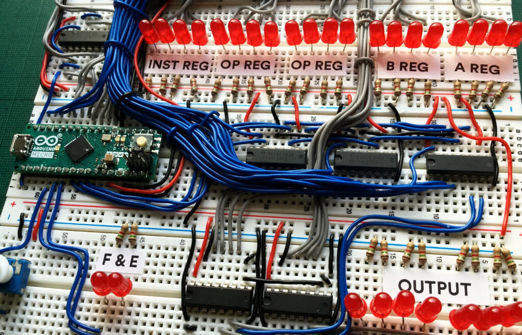
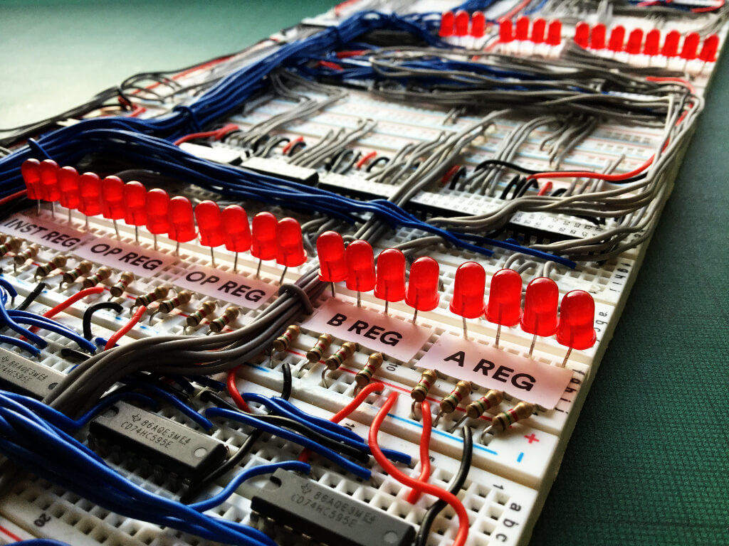
Richard of ARITH-MATIC had the idea to build a 4-bit computer based on 7400 series ICs (like the 74HC273, 74HC193, and 74HC125), but other responsibilities got in the way of this becoming a reality for quite some time. Finally, with the Retro Computer Festival at the Centre for Computing History in Cambridge, England held earlier this month, he went ahead and started the project in hopes of creating a working computer in under 30 days.

The resulting homebrew CPU is known as the ‘Cambridge-1,’ comprised mostly of 7400 series ICs, wiring, and an SRAM chip for storage carefully arranged on a set of breadboards. In addition to the other components, an Arduino Micro is also implemented. While not technically a retro device, the Arduino allowed him to “change the control logic on-the fly,” and gave him the flexibility to finish the project in his compressed time scale.

Arduino Blog 26 Sep 19:01