My DIY BB-8: Problems, Solutions, Lessons Learned
Imagine trying to make a ball-shaped robot that rolls in any direction but with a head that stays on. When I saw the BB-8 droid doing just that in the first Star Wars: The Force Awakens trailer, it was an interesting engineering challenge that I couldn’t resist. All the details for how I made it would fill a book, so here are the highlights: the problems I ran into, how I solved them and what I learned.
The Design Criteria: Portable and Inexpensive

I had two design criteria in mind. The first was to keep it low-cost. Some spend $1000 to $1500 on their BB-8s. I wanted to spend as little as I could, so as many parts as possible had to come from my existing stock and from online classifieds and thrift stores. Not counting the parts that were discarded along the way, the cost came in just shy of $300.
The second design criteria was to make it portable. It had to be something I could take on the bus or carry while walking a reasonable distance (I once carried it twenty-five minutes to a nearby school).
Both of these criteria meant that it had to be smaller than full size. A full size ball is 20″ in diameter. Mine has a 12″ ball which makes it 3/5 scale. Also, the larger it is, the more powerful and costly the motors, batteries, motor controllers, magnets, and so on.
Version One: Quick And Easy

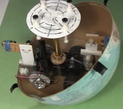
First I tried a minimalist approach. For the ball, I found my 12″ cardboard globe on kijiji.ca. I bought an RC toy truck at a yard sale and attached a pole to it for holding magnets near the top of the globe. I then made a head with corresponding magnets under it. The head magnets attract to the pole magnets, keeping the head on. Meanwhile, the truck rolling inside the ball makes the ball move.
Making the ball roll around was easy. Making it roll around while keeping the head on was very hard. The magnets at the top of the pole attract the magnets under the head, pulling them down hard onto the surface of the globe. That essentially glues the truck to the top of the globe.
To overcome that the truck needs sufficient traction. That also means the truck needs to be heavy. And lastly, the truck’s motor needs to be powerful enough to overcome its own weight and the grip of the magnets on the ball. The alternative is to make the magnetic attraction weaker, but if it’s too weak the head falls off. It’s a tricky balancing act, in both senses of the word.
But the most dome-like head I could make stay on was just a cardboard skeleton. Anything more filled out would be heavier and require a stronger magnetic attraction. The toy truck’s motor would not be up to it.
Version Two: Drill Motors And Drill Batteries
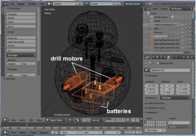
For more powerful motors and more mass I figured I could kill two birds with one stone by going with drill motors and drill batteries in a hamster drive configuration. Using drill parts kept costs down as the batteries and one drill came from yard sales while the other drill was free through freecycle.org. Meanwhile, both are heavy.
To make sure it all fit, I drew up a 3D model in Blender, the free 3D modelling and animation software that I use a lot. In fact, finding out how to make the batteries and motors fit was the first step. They had to be as low as possible. Their large mass low down is what keeps the droid vertical, with the much lighter head at the highest point.
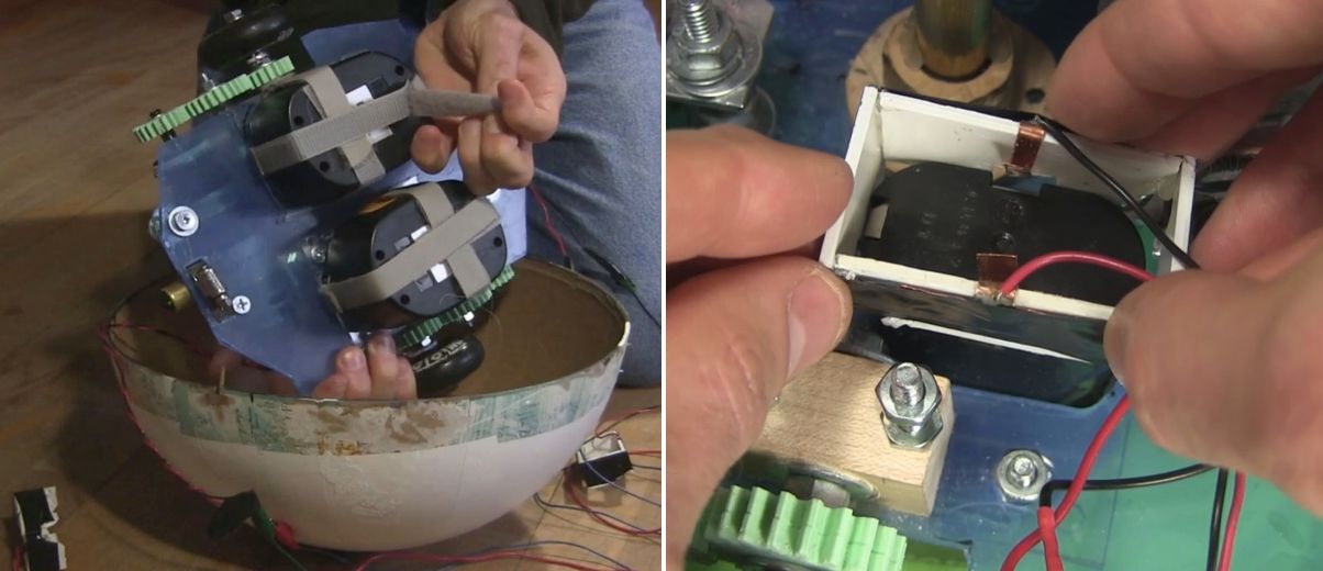
The drill batteries had to be easily removable for recharging. To hold them under the drive plate I simply used Velcro. Meanwhile, the drill battery stems went up through a hole in the drive plate. I made a connector to electrically connect to the battery terminals. It is a plastic rectangle with thin copper sheet metal for the contacts. Once the battery was Velcroed in place, this plastic and metal piece was lowered down onto the stem, the copper metal making contact with the battery terminals.
The Electronics
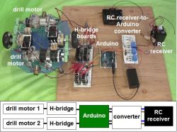

For the brains I used an Arduino UNO. To drive the motors I had all the parts for making two H-bridge driver boards, with the exception of 4 MOSFETs and some fuses. The Arduino does pulse width modulation (PWM) to the driver boards for speed control, as well as playing sounds at certain times when the motors are turned on.
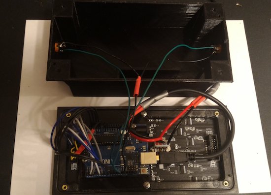
For remote control, I hacked the RC receiver from the toy truck and added an extra set of AA batteries in parallel for more runtime. A problem I ran into right away though, was that the RC receiver put out voltages of both polarities based on which direction the motors should rotate, whereas the Arduino’s pins take only positive voltages. To solve that I came up with a converter board to go between them.
Getting all that to work reliably took a while. Before I added fuses, I burned a few MOSFETs. At one point I’d put an N-type MOSFET where a P-type should have gone and vice versa. That resulting problem alone took a few days of spare time to figure out.
The wheels were old Rollerblade wheels — I keep a small bucket of these in my shop. I decided I wanted the ball to roll at around 1 foot per second and doing the math, that meant the wheels would have to rotate at around 2 rotations per second or 120 RPM. I found a PWM value that would give something close to that and started blowing fuses. I started with 1 amp fuses, then 2, 5, and finally settled on 10 amp fuses.
My final hurdle was that the motors would behave oddly when the motors were told to turn in opposite directions but were fine when they were told to turn in the same direction. This turned out to be a bad assumption on my part about how the RC receiver was wired internally — none of the output wires were common inside. After some changes to the circuit, I now had stable electronics.
I had basically been treating the RC receiver as a black box, but when I asked for help about my converter board here on Hackaday, it was pointed out that the receiver likely contained H bridges. Opening it up, that’s exactly what I found. The converter board works fine for now, but in the near further I’ll use one of the suggestions from that Hackaday post to eliminate the board altogether. I might even try all of the suggestions, just for fun.
The Drive System
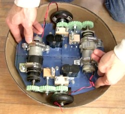
The motors were too long to fit in line between the wheels and so had to be mounted off to the sides. To transfer rotation to the wheels, I drew up some gears in Blender and 3D printed them at our local University of Ottawa Makerspace. In the print settings I used 2 shells and only 50% infill. The gears are held firmly onto the shafts solely using nuts and washers on either side. They’ve held up amazingly well, even with slipping and grinding during development.
For the bearings for the center gears and the wheels I used an old trick of making bearing blocks from hardwood.
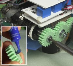
I wanted to keep as much room as possible on the drive plate available for adding things later and so initially I’d mounted the motors at only three points. But this allowed the motors to move a little causing the gears to slip. To fix that I later added a fourth mounting point and haven’t had any slipping since.
At the end of the shaft for the drill motors is a hole that a screw goes into. That’s part of how the chuck is kept on a drill motor, and that’s how one gear was kept on. However, this screw had a tendency to get loose. Putting a little Loctite on the threads fixed that.
Stability
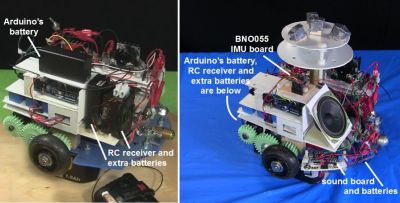
Given that I was trying to fit a lot in a small droid, I had to mount some things higher than I’d have liked to. When the droid stops, mass high up causes the droid to wobble. In the BB-8 droid used for promotional events they’ve gone to a great extent to keep the majority of the mass as low as possible. Originally I had the Arduino batteries and the RC receiver with its extra batteries fairly high up. I later mounted them much lower. When holding the internals in my hands I could tell the difference but it didn’t make a noticeable difference with the wobble.
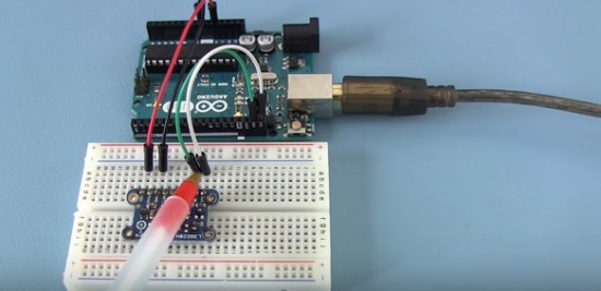
Instead, for that I added Adafruit’s BNO055 inertial measurement unit (IMU) board. With it I could tell what angle the droid was at when stopping and experimented with PID loops and other algorithms of my own to minimize wobble. That helped.
The Ball
As I said, I used a 12″ cardboard globe. To increase the traction of the wheels inside the globe I sprayed the globe’s interior with an anti-slip spray from a hardware store. This made a huge difference. However, over time the anti-slip coating vanished, and so I’m looking for another, more permanent coating, perhaps urethane or something. If anyone has any suggestions, please let me know in the comments. It also has to stop off-gassing eventually. The anti-slip spray had an odor for a long time.
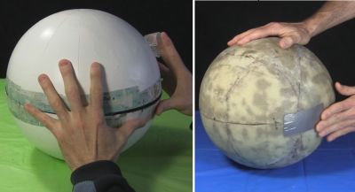
But the main problem with the cardboard globe was its thinness. With the huge weight of the internals pushing down on it where the wheels are, it warped significantly and required a lot of effort and a copious amount of tape to keep the two hemispheres together. This large amount of tape also made an uneven ridge for the head to slide over, making it get stuck. At that point either the drive system continued to move while the head fell off or the drive system couldn’t move at all.
The solution was to carefully coat a new globe in three layers of fiberglass. I took my time doing this, over a month and a half, applying one piece at a time and then sanding before putting the next piece. The result was a fantastic improvement. It no longer deformed and now it takes a minimal effort to attach the two hemispheres with only eight narrow strips of transparent duct tape.
The Never-ending Saga

My BB-8 is now at the point that I can call it finished. At least it’s finished as far as all the engineering is concerned, and that’s usually where I call it quits.
While the paint job worked out well, up close you can see that the details are painted on. It’d be nice to have at least the lines on the head be actual grooves. Also, these drill motors are brushed motors and I’ve since learned that doing high frequency PWM to brushed motors damages them over time. I’d like to replace them with brushless motors. And as anyone who’s use cordless drills a lot knows, drill batteries don’t last long, and so it’d be great to switch to LiPos.
But for now, the reactions I get from both kids and adults is beyond my wildest expectations. Kids threat it like a friend while adults have petted it and called to it like it was a baby or a dog wagging its tail. I’d call that a success.
Filed under: Hackaday Columns, robots hacks