Posts with «arduino uno» label

A giant, Arduino-powered scrolling LED sign costs $15/foot
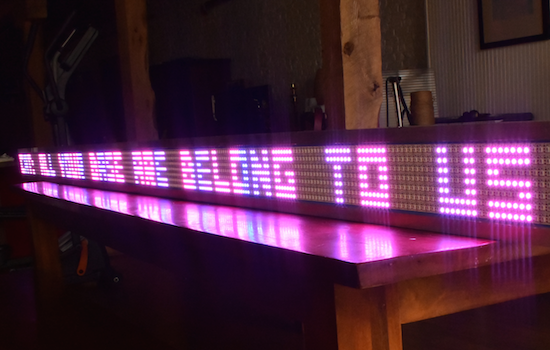
If you’ve ever wanted your own Times Square-like zipper, albeit a little smaller, you’re in luck. That’s because Josh Levine has created a giant scrolling LED display costing around $15 per foot, which consists of an Arduino Uno, a power supply, and seven programmable NeoPixel strips. The Maker also used a few pieces of plywood with a couple of aluminum angles glued to the top and bottom to enhance its sturdiness and appearance.

Equipped with 2,688 RGB pixels, the 12-foot-long sign is capable of showing text at 80 frames per second. Aside from basic scrolling messages, other features include a countdown timer with lookup-based gamma correction, column-by-column color control, custom fonts, sprite graphics with animation, and more.

The build is so simple, that you should be able to figure it out from looking at the pictures. Stick the strips to something, add some power, connect the Arduino data out pins to the strips’ data in pins.

The secret sauce is in the software. You can read about the parallel processing technique used here.

Bigger is better, right? Levine chose this size for his ticker only because it was the longest thing that could make it down his staircase–plus 400-pixels-long gives a refresh rate of 80 frames per second, which is just fast enough for nice animations. That being said, the Maker does note that he’d love to one day build a 100-foot-long sign “if you could find him a long enough surface to mount it on.” Until then, you can see it in action below and read all about the project on its page.
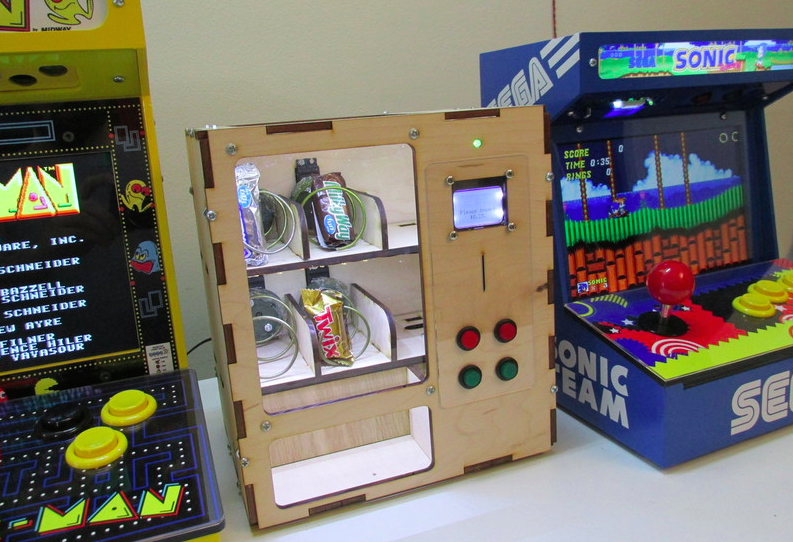
Venduino is a DIY Arduino vending machine

Ryan Bates has built a miniaturized vending machine from scratch using an Arduino Uno, four continuous rotation servos, and a Nokia 5110 LCD. The device, dubbed “Venduino,” includes four input buttons to make a selection, an LED indicator, and a 12V light strips to illuminate the inside of the cabinet. Whether it’s candies, toiletries, game cartridges, or miscellaneous items you’re looking to dispense, the possibilities are endless. Simply insert a coin, choose a product, and repeat.

Sound like something you’d like in your dorm room or cubicle? Bates has shared his code and schematics, and provided a detailed breakdown of his build below.

Maker builds his own Ghostbuster proton pack

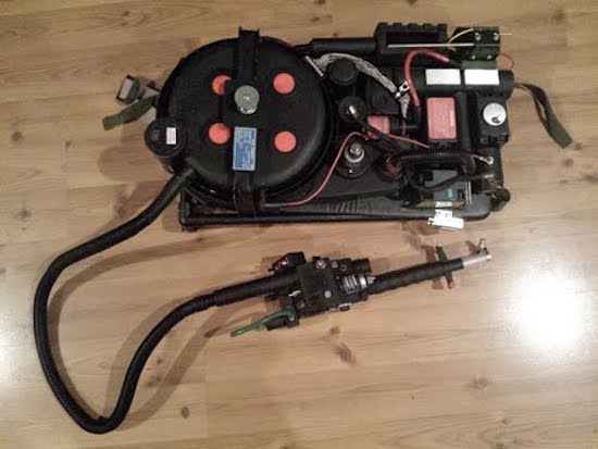
Anyone who has ever watched Ghostbusters is surely familiar with the iconic proton pack–the combination of a handheld wand and backpack-sized particle accelerator that’s the weapon of choice for weakening ghosts and aiding in capturing them. And with a remake of the ‘80s flick coming out in a few days, what better time for a DIY prop equipped with full-featured user control and Hollywood-like effects?

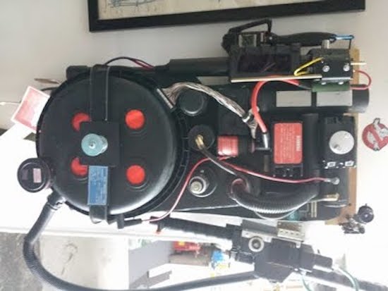
That’s exactly what John Fin has done using a bunch of household items, including a five gallon bucket for the cyclotron, a garlic powder container for the N-Filter, a hairbrush for the PKE meter, as well as spark plug wire, cardboard tubes, pill bottles, handles from power tool cases, and a couple electrical boxes and miscellaneous parts.

The proton pack is based on an Arduino Uno along with a Seeed Studio SD card shield containing .WAV files. The Arduino supplies all of the sound and light effects, except for the cyclotron lights which use a 555 timer and 4017 decade counter. The sound is amplified through an old computer speaker board, while two homemade boards control the lights.

The red lights on the cyclotron area are supposed to be asymmetrical. This project took two weekends to make, one for the pack and one for the gun. It is attached to a homemade  PVC “ALICE” frame. I tried to make it as light as possible, the whole unit weighs just 13 lbs. Its not fully “screen accurate” but more like a “Model 3″ version. The addition of a bunch of actual electronic components make it look more like it is a  functional unit instead of a prop.

The power meter on the gun and pack are synced to show an accumulating “charge” while a generator sound plays. When armed, the lights on the gun blink and the generator sound intensifies. When it’s fired, the barrel lights and the blast sound plays as the charge meter decreases to zero. It then shuts off and recharges.

It came out so well I also made a PKE meter (ghost detector) that also functions with lights and sound. The arms are powered by a small gear motor. The lights are a blinking LED and 10 green LEDs that sequence via a 555 timer/4017 decade counter. It’s crammed into a hairbrush.

I also have made a ghost trap and pedal that opens and closes via a servo mechanism. The interior of the ghost trap is made from an old laser disc lit with a row of LEDs, so it looks “deeper” inside than it should. It works with the pedal as it does in the movie. It’s not full height, I am trying to keep all this stuff compact. Anyway, after 30 years I’m sure there would be some miniaturization in the equipment by now!

And what would a full Ghostbusters getup be without some goggles. Fin constructed his own pair from scratch using foamboard and paper with aluminum strips for strength. The outside is textured to resemble a military-type finish, while the lens tubes illuminate green to add a “glow,” and a red LED blinks on the side.

Whether a fan of the movie, a fan of cosplay, or simply a fan of making, you’ll want to check out the entire build here.

Arduino simulator puts you in the driver’s seat of a toy car

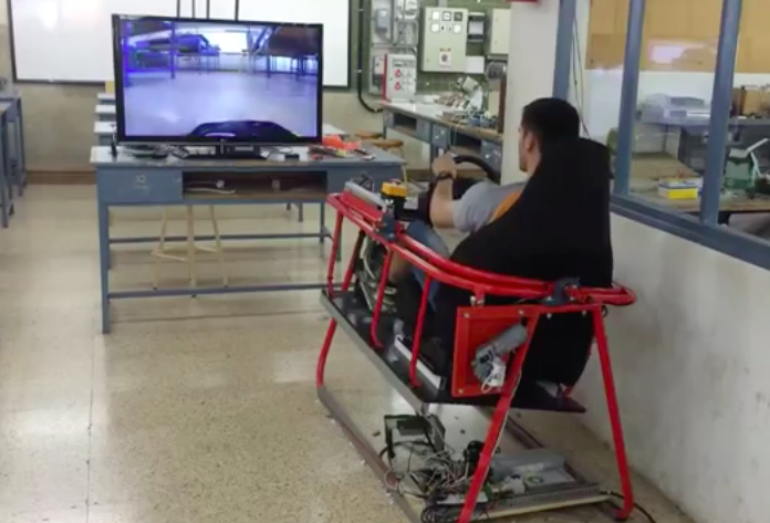
As part of their final project at EDN – Navàs, robotics students Rafart Jordi and Marc Thomas recently built an impressive Arduino simulator that captures video from a camera-equipped RC vehicle and displays it on a TV screen, making it feel as though you’re in the driver’s seat of a shrunken-down car.

The simulator is driven by an Arduino Uno along with an IBT-2 H-Bridge to control the 24V motors, and wirelessly communicates with the modified toy car via an XBee module.

You have to see it in action below!

DIY dtmf module and interfacing with arduino uno


In this post, we are going to make dtmf module and interface it using arduino.

My prototype

Theory of  DTMF:
Full form of dtmmf is dual tone multi frequency. The DTMF telephone keypad is laid out in a 4×4 matrix of push buttons in which each row represents the low frequency component and each column represents the high frequency component of the DTMF signal. Pressing a key sends a combination of the row and column frequencies. For example, the key 1 produces a superimposition of tones of 697 and 1209 hertz (Hz). Initial pushbutton designs employed levers, so that each button activated two contacts. The tones are decoded by the switching center to determine the keys pressed by the user.
DTMF keypad frequencies (with sound clips)
1209 Hz1336 Hz1477 Hz1633 Hz
697 Hz123A
770 Hz456B
852 Hz789C
941 Hz*0#D
We have to decode the dtmf tone generated by the phone. We can decode it using decoder ic i.e. MT8870.

Circuit diagram of  dtmf decoder ic:

Schematics

where 104 is 0.1 uF ceramic capacitor.
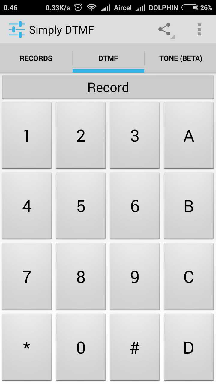
If it is not working with you android, then download this android app.


Arduino code:

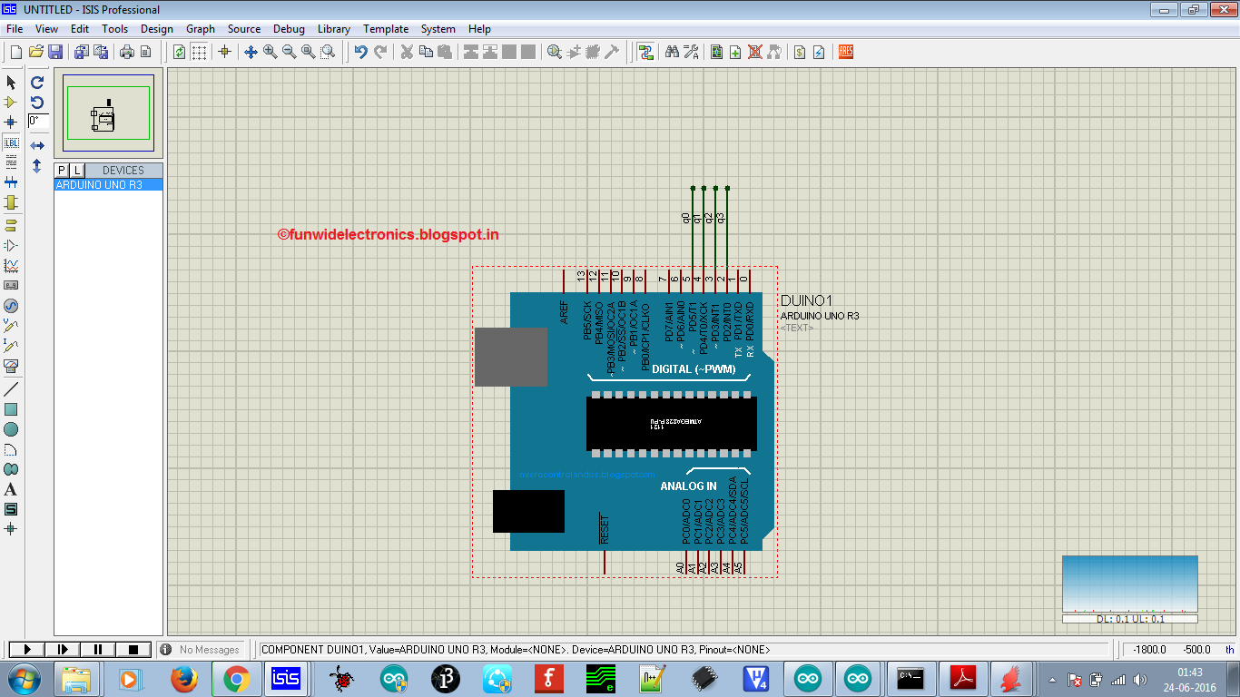
Proteus design
/* DOCUMENTATION: 
 *  INTERFACING DTMF MODULE WITH ARDUINO
 *  IT HAS FOUR DIGITAL OUTPUT'S i.e. Q0, Q1, Q2 AND Q3
 *  Q3 IS CONNECTED TO DIGITAL PIN 2
 *  Q2 IS CONNECTED TO DIGITAL PIN 3
 *  Q1 IS CONNECTED TO DIGITAL PIN 4
 *  Q0 IS CONNECTED TO DIGITAL PIN 5
 *  
 *  We will check the output using serial monitor
 *  By- Chandan Kumar 
 *  Contact: chandan90420@gmail.com
 */
int val=0;

boolean q0=LOW,q1=LOW,q2=LOW,q3=LOW;

void setup() {
  pinMode(2, INPUT);
  pinMode(3, INPUT);
  pinMode(4, INPUT);
  pinMode(5, INPUT);
  Serial.begin(9600);
}

void loop() {
q0=digitalRead(5); 
q1=digitalRead(4); 
q2=digitalRead(3); 
q3=digitalRead(2); 

val=q0+(q1*2)+(q2*4)+(q3*8);

Serial.println(val);

delay(400);
}

Thanks for visiting my blog.

Stay tuned for more updates !! 


FunWithElectronics 23 Jun 21:21

Maker adds gesture control to a surgical robotic

The Da Vinci system is one of the most popular surgical robots around, which allows surgeons to perform operations through only a few small incisions. The device works by translating a doctor’s hand movements into smaller, precise movements of tiny instruments inside the patient’s body. As ubiquitous as they may be in hospitals, chances are it’s never been operated quite like this before.

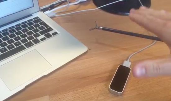
That’s because Julien Schuermans has managed to connect the robotic surgical tool’s hardware up to a LeapMotion controller, making its small forceps gesture-controlled. You can see how it all works in the video below.

As The Verge explains, four Arduino Uno-controlled servos are fitted to the pulleys and cables that handle the rotation, angle and gripping mechanism. Gesture input is captured by the Leap Motion’s infrared cameras, which is then converted into instructions for these servos, enabling the user to command the endoscopic device with just a wave of the hand.

An Arduino flying start lap timer

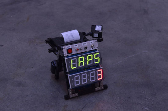
Richard Garsthagen recently became the proud owner of a Razor Crazy Cart. Seeing as though he only had one, racing against others was a bit out of the question for now. Being the Maker that he is, he came up with a solution instead: an Arduino Uno-based lap timer.

The lap timer uses an infrared light bridge to detect when something crosses the line, an Adafruit 7-segment display to show the time and lap count, as well as a SparkFun thermal printer that spits out the final results. The frame itself is constructed out of MakerBeam components, while power is supplied through an 11.2V LiPo battery.

Meanwhile, the Arduino software has two modes:

Race mode: This is started by clicking the left “race” button. This will start the laptimer. It uses a “flying start” principle. So there is no count down, just start racing, when the first time you cross the line, the timer will start. It will display the amount of laps still to go on the top 7-segment display and the time on the second 7-segment display.

Setup mode: When you click on the “menu,” 2nd button, you can setup how many laps you want to race. By turning the pot-meter you can select between one and nine laps.

While he may be using his timer for Crazy Cart, the system can come in handy whenever you’re unable to directly race someone else — whether that’s running or cycling around the house. Want one of your own? Race on over to its project page. In the meantime, check it out in the video below. (We gotta say, the 8-bit chiptunes were a nice touch!)

BINARY IO is an Arduino-powered, four-button MIDI controller

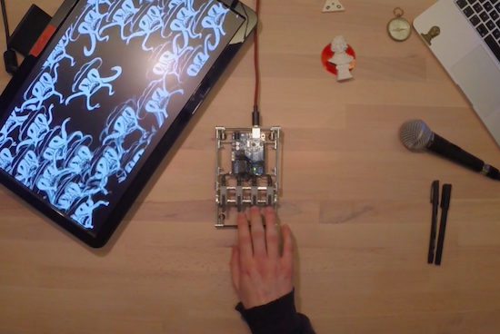
Developed as part of a semester project, BINARY IO is a nifty little MIDI controller capable of counting from one to 15 using only four buttons. The device, which uses binary code as an input mechanism, is powered by an Arduino Uno and Max/MSP.

With a little practice, BINARY IO becomes quite intuitive and fun to play. As demonstrated by its creators Benjamin Weber and Jeremy Ondrey, users can piece together new music with sounds ranging from the piano to the xylophone to the drums.

A DIY Arduino Nixie tube clock

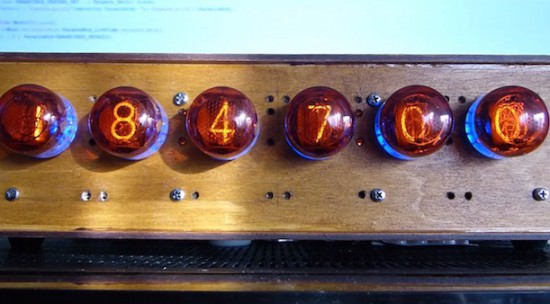
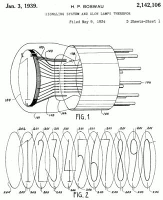
Nixie tubes have a lot of fans because of their retro style. They are neon valve tubes, where 10 cathodes shaped like numbers from 0 to 9 are switched on by plasma when high voltage flows through them. Patented in the 1930s by H.P. Boswau, they were wildly popular in the ‘60s and remained so until LEDs became cheaper to manufacture in the ‘70s. Many Makers today are creating vintage-look clocks using, now rare, Nixies bought on eBay with the help of an Arduino or Genuino Uno to control them.

In the video below, Jozsef Kovecses built a Nixie clock with NTP time syncronization using a Genuino Uno, a Geeetech IduinoShield, DS1307 RTC, DC-to-DC converter, and Nixie tube modules to drive the tubes directly.

Arduino Blog 15 Jun 11:55

Make masterpieces with a homemade CNC painting machine

Longtime artist Jeff Leonard has built a pair of Arduino-driven CNC painting machines with the motivation to grow his toolbox and expand the kinds of marks he could make simply by hand. By pairing the formal elements of painting with modern-day computing, the Brooklyn-based Maker now has the ability to create things that otherwise would’ve never been possible.

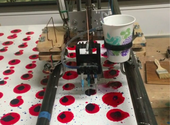
Machine #1 consists of a 5’ x 7’ table and is capable of producing pieces of art up to 4’ x 5’ in size. The device features a variety of tools, including a Beugler pinstriping paint wheel, a brush with a peristaltic pump syringe feed, an airbrush with a five-color paint feed system and five peristaltic pumps from Adafruit, a squeegee, and pencils, pens, markers and other utensils.

In terms of hardware, it’s equipped with three NEMA 23 stepper motors, three Big Easy Drivers, as well as an Arduino Mega and an Uno. There are two servos and five peristaltic pumps on the carriage–the first servo raises and lowers the tool, while the second presses the trigger on the airbrush. An Adafruit motor shield on the Uno controls the pumps, and the AccelStepper library is used for the Big Easy Drivers.

According to Leonard:

I am coding directly into the Arduino. There are many different codes that I call and overlap and use as a painter overlaps techniques and ideas. There is a lot of random built into the code, I don’t know what the end result will be when I start. Typically on any kind of CNC machining the end result has been made in the computer and the machine executes the instructions. I am building a kind of visual synthesizer that I can control in real-time. There are many buttons and potentiometers that I am controlling while the routines are running. I take any marks or accidents that happen and learn how to incorporate them into a painting.

I am learning Processing now and how to incorporate it into the image making.

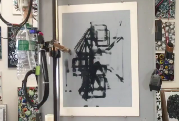
Machine #2, however, is a bit different. This one is actually a standup XY unit that was made as a concept project. It paints using water on magic paper that becomes black when wet and disappears as it dries, used mainly as a way to practice calligraphy or Chinese brush painting. Not only does it look great, there’s no clean up either!

In terms of tools, the machine has a brush and an airbrush. Two NEMA 17 stepper motors are tasked with the XY motion. There are also three servos–one servo lifts and lowers the armature away from the paper since there is no Z-axis, another controls the angle of the brush, and the third presses the trigger of the airbrush. A peristaltic pump helps to refill the water cup, along with a small fan. The system is powered by an Arduino Uno with an Adafruit Motor Shield using the Adafruit Motor Shield Library v2.

As awesome as it all sounds, you really have to see these gadgets in action and their finished works (many of which can be found on Instagram).