Posts with «3d printing» label

3D Print and Program This Adorable Bipedal Arduino Bot

Build an Arduino-powered, 3D-printed, moon-walking bot with preprogrammed and custom gaits.
Read more on MAKE

The post 3D Print and Program This Adorable Bipedal Arduino Bot appeared first on Make: DIY Projects and Ideas for Makers.

Make your own 3D-printed sonic tractor beam with Arduino

From magic to science, man has long dreamed about being able to manipulate objects from a distance. People have been able to push something using air or even sound waves for a while, but University of Bristol researcher Asier Marzo and colleagues have come up with a 3D-printable device that can not only repel small items, but can also attract them to the source.

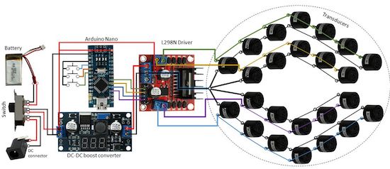
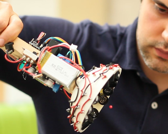
It does this using an array of sound transducers arranged in a dome shape at the end of a wand. The acoustic tractor beam is also equipped with an Arduino Nano, a motor controller board, a DC-DC converter, and a LiPo battery, among some other easily accessible components.

Basically, an Arduino will generate 4 half-square signals at 5Vpp 40kHz with different phases. These signals get amplified to 25Vpp by the motor driver and fed into the transducers. A button pad can be used to change the phases so that the particle moves up and down. A battery (7.3V) powers the Arduino and the logic part of the motor driver. A DC-DC converter steps-up the 7.3V to 25V for the motor driver.

Aside from entertaining friends by levitating small pieces of plastic, the DIY tractor beams have many possible use cases, particularly in biological research. However, there are some limitations. Given the challenge of suspending objects more than half the wavelength of sound, the gadget can only trap things around a few millimeters in size.

Marzo and his team have published their project in the journal Applied Physics Letters, and shared step-by-step instructions so you could get started on building your own beam. You can read more on Phys.org as well.

This 3D-printed bionic hand can replace or support a limb

3D-printed appendages are, as one might suspect, generally meant for those that are missing a limb. Moreover, there are many other people that might retain partial functionality of a hand, but could still use assistance.

Youbionic’s beautifully 3D-printed, myoelectric prosthesis is envisioned for either application, capable of being controlled by muscle contraction as if it were a real body part.

As seen in the video below, the Youbionic hand can manipulate many different items, including a small box, a water bottle, and a set of keys. Functionality aside, the movement is extremely fluid and the smooth black finish really makes it look great.

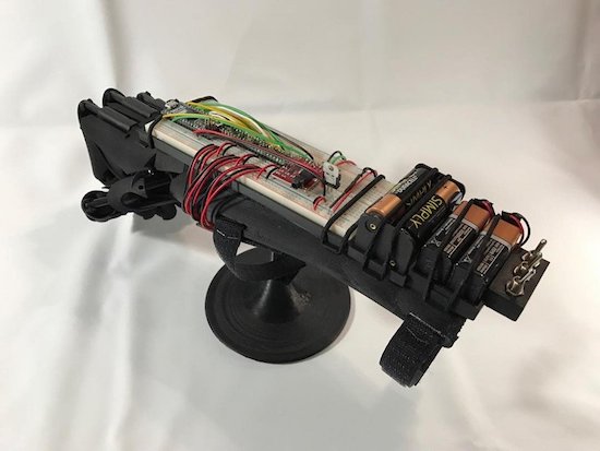
The device is currently equipped with an Arduino Micro, servos, various sensors, a battery pack, and a few switches. Even the breadboard appears to be very neat, though one would suspect the final version will use some sort of PCB.

You can learn more and order yours on Youbionic’s website.

RooBee One is an open-source SLA/DLP 3D printer

Aldric Negrier, a Portuguese Maker and owner of RepRap Algarve, has created an SLA 3D printer named RooBee One.

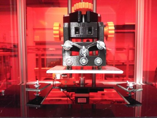
Most desktop 3D printers that you’ll see in Makerspaces or advertised for home use drop material onto a bed using a hot extrusion head. The open-source RooBee One, however, employs a DLP projector along with an Arduino Mega to light up each layer in a vat of resin. This causes each layer to solidify, thus making a complete object. You can see this process at around 0:30 in the video below.

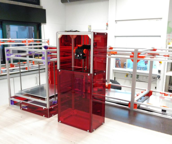
RooBee One features an aluminum frame with an adjustable print area of 80x60x200 mm, with up to a 150x105x200mm build volume. Aside from the Arduino, additional electronics consist of a RAMPS 1.4 shield, a NEMA 17 stepper motor, a microstepping driver, an endstop, and a 12V transformer. Negrier also installed a fan on top of the printer to help guide the toxic vapors outside and away from the machine’s operator.

This process may be unfamiliar to those used to “normal” 3D printers, as it “magically” pulls a complete part out of a bath. The project is fairly involved, but the resulting ruby-red machine looks quite impressive. You can find out how to build one on its Instructables page.

Quad Walker

Primary image

What does it do?

Been working on a building a quad walker probably for a year now. What started of a coding project has now ended up with me learning how to 3d model and building a kit 3d printer.

The size of walker also grew, it started of using little 9g servos and now using full-size r/c car servos.

At moment, I’ve only modelled the leg at the moment, though I’m reasonable confident this will be the near final version before starting the body.

Will post more soon

Cost to build

Embedded video

Finished project

Number

Time to build

Type

legs

URL to more information

Weight

Quad Walker

Primary image

What does it do?

Been working on a building a quad walker probably for a year now. What started of a coding project has now ended up with me learning how to 3d model and building a kit 3d printer.

Along with scope of the project, the size of walker also grew. It was originally planned to use small 9g servers and probably end up 20cm across in total. Though I moved to using standard r/c card servos and as a result each leg will be around 20cm. No idea how big the body will need to be to house everything else.

Cost to build

Embedded video

Finished project

Number

Time to build

Type

legs

URL to more information

Weight

read more

Quad Walker

Primary image

What does it do?

Been working on a building a quad walker probably for a year now. What started of a coding project has now ended up with me learning how to 3d model and building a kit 3d printer.

Along with scope of the project, the size of walker also grew. It was originally planned to use small 9g servers and probably end up 20cm across in total. Though I moved to using standard r/c card servos and as a result each leg will be around 20cm. No idea how big the body will need to be to house everything else.

Cost to build

Embedded video

Finished project

Number

Time to build

Type

legs

URL to more information

Weight

read more

Quad Walker

Primary image

What does it do?

Been working on a building a quad walker probably for a year now. What started of a coding project has now ended up with me learning how to 3d model and building a kit 3d printer.

Along with scope of the project, the size of walker also grew. It was originally planned to use small 9g servers and probably end up 20cm across in total. Though I moved to using standard r/c card servos and as a result each leg will be around 20cm. No idea how big the body will need to be to house everything else.

Cost to build

Embedded video

Finished project

Number

Time to build

Type

legs

URL to more information

Weight

read more

This phone-controlled robot can beat you in air hockey

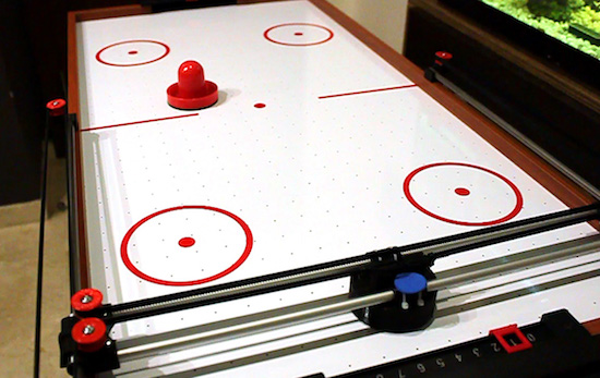
Air hockey is a classic arcade game consisting of two players, two paddles, a puck, and a low-friction table. But what happens if you don’t have an opponent? If you’re Jose Julio, you build a robotic one out of 3D printer parts.

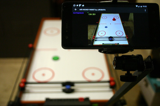
An updated version of his earlier design from 2014, Julio upgraded the Air Hockey Robot’s original camera and vision system to a smartphone for its eyes and brain. Other components include an Arduino, an ESP8266-based shield, NEMA 17 stepper motors, stepper motor drivers, as well as some belts, bearings, rods, and a few more 3D-printed pieces.

As you can see in Julio’s video below, the robot moves along two different axes with a paddle to cover its half of the table. An Android phone running the Air Hockey Robot EVO app monitors the playing surface, and makes real-time decisions by tracking the puck’s location and predicting its trajectories.

The smartphone’s camera is looking at the playing court. The camera’s captured data is processed in real-time by the smartphone. Detecting the position of the puck and the “pusher robot” (and according to the current location of all the elements on the court), your smartphone makes decisions and commands the robot what to do via Wi-Fi.

Your smartphone will become an augmented reality device, showing predicted trajectories and position of all the objects involved in this game.

Want your own? Julio has made both the instructions and code available to everyone.


Make Your Own Arduino Header Pins

There are two kinds of people in the world (and, no, this isn’t a binary joke). People who love the Arduino, and people who hate it. If you’ve ever tried to use a standard prototype board to mount on an Arduino, you’ll know what kind of person you are. When you notice the pins aren’t on 0.1 inch centers, you might think, “What the heck were those idiots thinking!” Or, you might say, “How clever! This way the connectors are keyed to prevent mistakes.” From your choice of statement, we can deduce your feelings on the subject.

[Rssalnero] clearly said something different. We weren’t there, but we suspect it was: “Gee. I should 3D print a jig to bend headers to fit.” Actually, he apparently tried to do it by hand (we’ve tried it, too). The results are not usually very good.

He created two simple 3D printed jigs that let you bend an 8-pin header. The first jig bends the correct offset and the second helps you straighten out the ends again. You can see the result in the picture above.

[Rssalnero] notes that the second jig needed reinforcement, so it is made to take 8 pins to use as fulcrums. Probably doesn’t hurt to print the jigs fairly solid and using harder plastic like ABS or PETG, too. Even if you don’t have a 3D printer, this is about a 15 or 30 minute print on any sort of reasonable printer, so make a friend. Worst case, you could have one of the 3D printing vendors make it for you, or buy local.

We love little tool hacks like this. If you are too lazy to snap 8 pins off a 40 pin strip, maybe you’d like some help. If you’d rather go with a custom PC board, you might start here.


Filed under: Arduino Hacks, tool hacks