

Posts with «arduino» label

The MAKERS Revolution
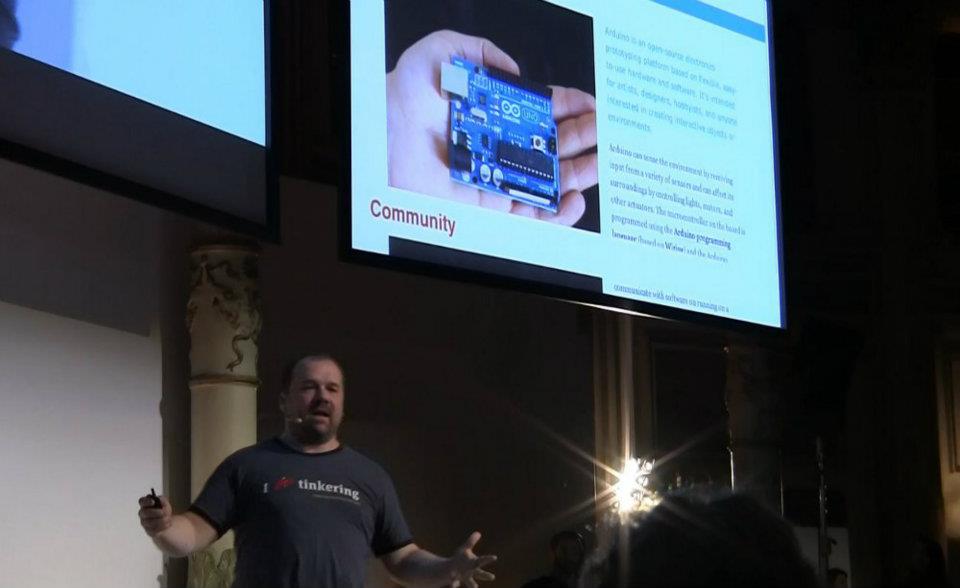
“A Thanks to Chris Anderson, Massimo Banzi, Dale Dougherty and the MAKERS of the new Industrial Revolution.
On March 9 in the Acquario Romano we heard testimonies of people, reality and Italian companies that have never stopped believing in innovation.
We like the stories of those who invest in their future without fear and looking to new technologies.
Just as we love the old craftsmen who know how to reinvent traditions. We know that it takes courage to get involved.
World Wide Rome has shown us that there are opportunities to do business.
No time to lose.
We want this event would mark the beginning of something new.
We would like the genius of provocation Makers became a model of development.
Let’s get to work.
” [World Wide Rome]
We were there and we show you the key notes of Chris Anderson, and Dale Dougherty.

See the video covered by copyright.


Intutive training aid using wearable electronics
A yet another application of wearable electronics – to train blind athletes with pressure feedback.
A work that is a part of the Innovation Design Engineering (IDE) masters programme run jointly by Imperial College and the Royal College of Art has a team designing it, as part of course. Mining company Rio Tinto has launched a ‘Sports Innovation Challenge’ for new paralympic opportunities, ranging from equipment through to radical new sporting events and competition models.
“As a visually impaired person, you don’t develop the same kind of kinaesthetic awareness — so we began with how you can rebuild body awareness and how you can actually have a feeling of where your limbs are in space, if you lost your sight, for instance,” said IDE student Benedict Copping.
Noting that the vast majority of sighted athletes use coaching demonstrations or video-analysis techniques to perfect complex motion skills, Copping’s team wanted to find a way for blind athletes to similarly benefit.
The design comprises of wearable joint pads that record the position of the limb in space and keep this as a reference against predetermined angles, giving a graded vibration feedback as they match up.
Flex sensors, vibration motors (like those used in mobile phones) and an Arduino mini pro electronics board (for computation) are some of the easily available components that are used.
“If you’re visually impaired, because you can’t reflect on somebody else doing the motion, the coach moves the hand around, so what he’ll do is get the first position and press a button, store that, then [get a] second position, store that — so a combination of points together will build a picture. Then when you actually change movements, it will vibrate more and more until you get the correct position,” Copping said.
For creating the winning design, the Ghost team (which also includes Jason Cheah, Shruti Grover and Idrees Rasouli) will receive undisclosed funding from Rio Tinto to further develop the technology.
[Via: TheEngineer]
Feeding the dog over twitter
Many times you would have wished that you could take care of your dog remotely instead of letting a careless friend handle him. The answer to the problem is this ingenious twitter based feeding device by Nat Morris.
Theres a Nanode microcontroller (an Arduino clone with ENC28J60 ethernet), LCD screen from an old Dell laser printer, the stepper motor mechanism is out of a HP Deskjet 500 from the 90′s. The stepper is controlled via a ULN2003 and a 555 timer is used for the buzzer. Theres a pair of IP cameras (ones broke at the moment) and a server process which polls twitter and co-ordinates it all.
So how many more applications can you think of using the same concept? ![]()
[Via: webpronews]
Raspberry Pi
Thanks to Mark Guzdial’s Computing Education blog, specifically this post, I recently found out about the Raspberry Pi, a Linux board that is retailing for $35, with 256Mb RAM, 2 USB ports, an Ethernet port, and both RCA and HDMI video output (no VGA though an adapter can be had for ). The system on a chip they are using
is a Broadcom BCM2835. This contains an ARM1176JZFS, with floating point, running at 700Mhz, and a Videocore 4 GPU. The GPU is capable of BluRay quality playback, using H.264 at 40MBits/s. It has a fast 3D core accessed using the supplied OpenGL ES2.0 and OpenVG libraries.
…
The GPU provides Open GL ES 2.0, hardware-accelerated OpenVG, and 1080p30 H.264 high-profile decode.
The GPU is capable of 1Gpixel/s, 1.5Gtexel/s or 24 GFLOPs of general purpose compute and features a bunch of texture filtering and DMA infrastructure.
That is, graphics capabilities are roughly equivalent to Xbox 1 level of performance. Overall real world performance is something like a 300MHz Pentium 2, only with much, much swankier graphics.
This board seems to be at least 50 times as much processing and 8000 times as much memory as an Arduino for a similar price. You need to add an SD card to boot off of (I presume with a Linux system on the card), which raises the price by another $15–35 depending on how big a flash card you get (I’m assuming that 16gB or 32gB is about the right size—a smaller drive would be much cheaper).
There appear to be 26 general-purpose I/O pins, so I can see this processor becoming quite popular for higher-end robotics. With the ethernet connection, it may become popular for providing small LAMP (Linux-Apache-MySQL-PhP) servers, as long as everything can fit on the SD drive. It has an audio-out port, but you’d have to use a USB microphone to get audio in. The board can be powered over the USB line, or through a separate power port.
The default Linux is Fedora, but Debian and ArchLinux will also be supported. The Linux can be downloaded and put on an SD, or the SD flash cards can be bought preloaded.
This looks like a potentially very useful educational toy—cheap enough to mess around with and easy to start over from scratch (just write a new copy of the Linux onto an SD card). The only problem I can see is that Linux makes getting access to the I/O ports much harder than it needs to be, but I suspect that the developers have already written drivers and Python modules for accessing the I/O pins, so this may not be a problem. They plan to make Python the main development language for the Raspberry Pi (Python is slow, but even with interpreter overhead the chip would still be faster than an Arduino), but any language that has a compiler for the ARMv6 should work. I assume that Pyrex would be available for speeding up inner loops.
I may have to look into designing a motor shield for the Raspberry Pi, so that we can do robotics with Python programming!
Related articles
- In Depth: Raspberry Pi: everything you need to know (techradar.com)
- You can now run Arch & Debian Linux on a Raspberry Pi (zdnet.com)
- Raspberry Pi hits the market for $35 (cbsnews.com)
- Educators and Leaders Are Praising Low-Cost Raspberry Pi Devices (ostatic.com)
- Raspberry Pi (avc.com)
- Arch Linux now available for the Raspberry Pi $35 computer (liliputing.com)
- The $35 Raspberry Pi computer goes on sale (hazima.wordpress.com)
- $35 PC Sells Out in Minutes (mashable.com)
- Raspberry Pi is Ready to Buy! $35 Computer is so Popular it’s Crashing Websites with Sales (singularityhub.com)
- Reports: First Raspberry Pi Devices Sell Out Nearly Instantly (ostatic.com)
Tagged: Arduino, Linux, Raspberry Pi


listComPorts – Windows command-line tool for USB-to-serial
Did you know each Arduino has a unique serial number in its USB interface that you can use to distinguish one Arduino from another? If you deal with multiple Arduinos, knowing exactly which one is plugged into your computer can be a real time-saver. But actually getting at this serial number and mapping it to [...]
listComPorts – Windows command-line tool for USB-to-serial
Did you know each Arduino has a unique serial number in its USB interface that you can use to distinguish one Arduino from another? If you deal with multiple Arduinos, knowing exactly which one is plugged into your computer can be a real time-saver. But actually getting at this serial number and mapping it to COM ports can be challenging.
For Windows computers, here’s “listComPorts”, implemented both in GCC C code and in VBScript, both available from my usbSearch github repository.
It gives the COM port number, the manufacturer name, the USB Vendor ID and Product ID (VID & PID) and [...]
Sensor board for underwater ROV
Since I had bought the robotics club an I2C accelerometer and magnetometer, I decided to make a new PC board for them to mount the accelerometer, the magnetometer, and the pressure gauge on the same board. I don’t have the SMD soldering skills to solder all the chips onto one board, and I already had breakout boards for the accelerometer and magnetometer from Sparkfun, so I decided just to put connectors for those breakout boards onto the back of the pressure sensor board. (The back, because the pressure sensor on the front has to be stuck through a hole in the dry box and glued in place.
The new boards are tiny (1.05″ × 1.425″), so I decided to try BatchPCB (which has pricing by the square inch) rather than 4pcb.com (which has fixed pricing per board, up to a fairly large size). The price from BatchPCB was $10 per order plus $2.50/square inch plus $0.90 for shipping, so ordering 3 copies of the board (though I only needed one), cost me $22.12, substantially less than a single board from 4pcb.com, which is $33 plus $17.30 shipping and handling per board (plus an extra $50 if your board has multiple boards on it). The 4pcb price is lower if your board is bigger than about 15.76 square inches, so even my HexMotor boards (at 12.44 square inches) would be cheaper from BatchPCB. If you get multiple boards from 4pcb.com on a single panel and cut them apart yourself, the breakeven point is about 35.76 square inches for a single design (so three HexMotor boards from a single 4pcb.com panel is cheaper than from BatchPCB). For multiple designs on a single panel, the 4pcb.com deal is better: for 3 different designs, a total of 27.04 square inches would make 4pcb.com the cheaper way to go.
If you want a copy of the board, you can order it from BatchPCB, or pick up the Eagle files from my web site and order copies from elsewhere. I’ve put the HexMotor Eagle files on line also, but not put them on the BatchPCB site. I should probably upload them there sometime.
Bottom line: BatchPCB is better for small numbers of tiny boards, but 4pcb.com is better for larger boards and multiple designs.


The BatchPCB orders came back quite quickly (12 days from order to delivery by mail), though I had been worried because their design-rule check, which they say takes minutes had taken about 8 hours. The problem was that each check takes a few minutes, but they had hundreds in the queue over the weekend, and it took a full day to clear the queue.
I had less trouble soldering the pressure gauge this time (this was my second attempt at soldering surface mount devices). You can see in the pictures above that the results are much cleaner than in my first attempt.
The robotics club has tested the pressure sensor on the new board (using their own code on the Arduino) and it seems to work ok, have drilled the hole in the dry box for the port, and glued the sensor board in place using superglue. It seems to be waterproof (at least down to 1 foot—we’ve not tested in deep water yet).
Related articles
- Merged in my Arduino blog (gasstationwithoutpumps.wordpress.com)
- Learning to use I2C (gasstationwithoutpumps.wordpress.com)
- Magnetometer and accelerometer read simultaneously (gasstationwithoutpumps.wordpress.com)
- Magnetometer was not fried (gasstationwithoutpumps.wordpress.com)
- Turning a DIY Project into a Product (spectrum.ieee.org)
- Underwater ROV again this year (gasstationwithoutpumps.wordpress.com)
Tagged: accelerometer, Arduino, BatchPCB, magnetometer, pressure sensor, Printed circuit board, ROV, SparkFun Electronics


Arduino RFID shield
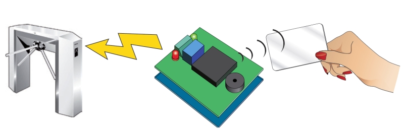
This shield could be used as a stand-alone transponder key, or with Google’s servers to create a cloud-computing application.

It’s time to present you an application with RFID. We want to show you how to use the popular Arduino to produce a device capable of recognizing passive transponder (TAG). But this is not the usual RFID key, because the system can activate a relay if a recognised TAG is read, but also we took the opportunity to make an application that use cloud-computing. The basic version, which is a simple key relay consists of an Arduino (Duemilanove or UNO) and the RFID shield based on a ID-12 of Innovations: placing a transponder already learned, the relay is activated.
The extended version of our project uses an Arduino, the RFID Shield and the Ethernet Shield with which we can access the Internet and stored, using the Google Docs service, the transponder data.
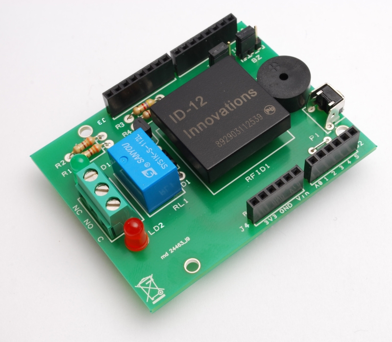
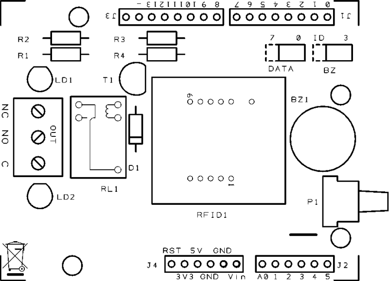
The RFID shield
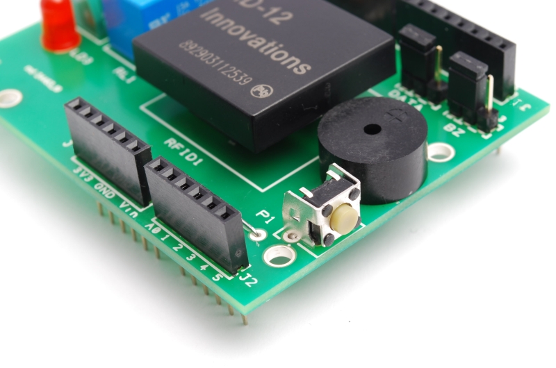
But before you see the applications in detail, we spend some words on the shield for Arduino that we need to capture data of passive TAG. It is a very simple circuit based on the form ID-12 , which contains a complete recognizer of passive transponders, in addition to a relay controlled by Arduino and a few other passive components. The buzzer, which allows you to set an audible alert, could be controlled by ID-12 or by Arduino.

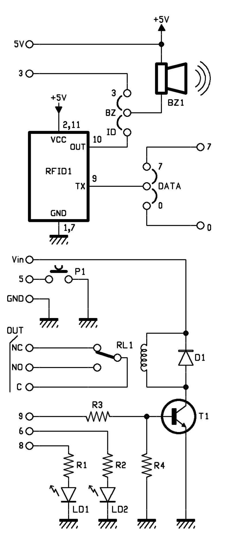
The relay is powered by Vin Arduino (and the corresponding contact of the shield) and GND. The base of the transistor that controls RL1 is driven by the pin 9 of the Arduino. The lines 6 and 8 control the lighting of the LEDs.
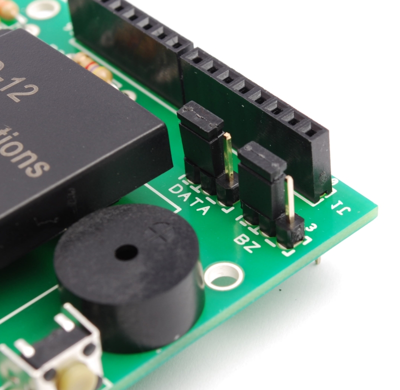
In our case, the pin 7 of ID-12 is connected to ground, so the chip will only recognize ASCII coded tag and return its output in ASCII characters.
The component has a TTL level serial interface, accessible from it’s pins 9 and 8, then there is an output (pin 10) that pulses rapidly (at a frequency of 3 kHz) every time the module detects the code of a tag encoded and used to drive a buzzer or a light emitting diode.
All data are read from Arduino using the library NewsoftSerial that allows to emulate a serial port; in our case, the emulation is carried on lines 7.
How it works
Once you put power to the system, when the module ID-12 reads a tag, the pin 10 pulse at 3 kHz and the Arduino read s data; then microcontroller compares the code with those who has in memory.
If the transponder is one of those already learned the micro actives the relay and the green led. This relay will be used to control an electric lock, a gate, etc..
In bistable mode, the relay changes state each time the ID-12 reads a valid tag.
Clearly, the circuit can work well if in his memory there is at least a RFID tag.
To learn the code for a tag and then write it to EEPROM, you must press and hold button P1 for 3 seconds (max. 5), once that is done you have to pass a card and wait for the confirmation sound (given by buzzer) and light (provided by the green LED).
At any time you can remove a tag code from memory: must press the P1 button for 5 seconds or longer, until the red LED lights on. At this point you release the button and pass the tag to be deleted, if the LED turns off and on again, the card has been deleted.
To erase the entire EEPROM you must restart the Arduino, and during the reboot, hold down the button P1 for about one second; when the red LED lights up. Done this, Arduino is ready to read new tags.
R1: 330 ohm
R2: 330 ohm
R3: 4,7 kohm
R4: 10 kohm
R2: 330 ohm
R3: 4,7 kohm
R4: 10 kohm
LD1: Led 3 mm green
LD2: Led 3 mm red
BZ1: Buzzer
T1: BC547
RFID1: ID-12
RL1: Relé 12V
P1: Microswitch 90°
D1: 1N4007
Varie:
- Screw 3 poli
- Jumper (2 pz.)
- Strip male 3 via (2 pz.)
- Strip M/F 6 via (2 pz.)
- Strip M/F 8 via (2 pz.)
/* RFID shield key created 2011 by Andrea Fainozzi This example code is in the public domain. http://www.open-electronics.org http://www.futurashop.it http://blog.elettronicain.it/ */ #include <EEPROM.h> #include <NewSoftSerial.h> #define PULSANTE 5 //pin relativo al pulsante da premere per entrare in modalità scrittura/cancellazione #define DATA_PIN 7 //scegliere il pin che si vuole utilizzare in base alla scelta fatta con il jumper sulla scheda (7 |#define RELE_PIN 9 //scegliere il pin che si vuole utilizzare in base alla scelta fatta con il jumper sulla scheda (9 | 10) #define BUZZ_PIN 3 //scegliere il pin che si vuole utilizzare in base alla scelta fatta con il jumper sulla scheda (3 | 11) #define GREEN_LED_PIN 8 //pin relativo al led verde #define RED_LED_PIN 6 //pin relativo al led rosso //scegliere cosa fare quando viene letta una scheda #define RELE 0 //scegliere '1' per fare in modo che alla lettura di una scheda il relè venga attivato '0' per non fare nulla #define BUZZER 1 //scegliere '1' per fare in modo che alla lettura di una scheda il buzzer emetta un suono '0' per non fare nulla #define LED 1 //scegliere '1' per fare in modo che alla lettura di una scheda corretta venga acceso il led verde e per una scheda incorretta il led rosso '0' per non fare nulla #define DURATA_RELE 1000 //scegliere il tempo per il quale deve rimanere acceso il relè (se viene inserito '0' il relè funzionerà in modo bistabile) boolean check; //variabile con la quale eseguo tutti i controlli all'interno dello sketch int on_off=0; //variabile che utilizzo per controllare lo stato del led in modalità bistabile NewSoftSerial mySerial(DATA_PIN,1); //inizializzo il pin sul quale leggere i dati trasmessi dall'ID-12 void setup() { if(DURATA_RELE>60000) //controllo che il tempo impostato per la durata di attivazione del relè sia inferiore a 1 minuto while(1){ //in caso contrario stampo su seriale un messaggio di errore in un ciclo infinito delay(2000); Serial.print("Tempo relè non valido, troppo alto"); } pinMode(PULSANTE,INPUT); //imposto il pin del pulsante in modalità input per verificare quando il pulsante viene premuto digitalWrite(PULSANTE,HIGH); //e lo setto alto, in modo tale da attivare la resistenza di pull-up if(RELE) //controllo se è stato scelto di attivare o meno il relè, nel primo caso, imposto il pin assegnatogli come output pinMode(RELE_PIN,OUTPUT); if(BUZZER) //controllo se è stato scelto di attivare o meno il buzzer, nel primo caso, imposto il pin assegnatogli come output pinMode(BUZZ_PIN,OUTPUT); if(LED){ //controllo se è stato scelto di attivare o meno i led, nel primo caso, imposto i pin assegnatogli come output pinMode(GREEN_LED_PIN,OUTPUT); pinMode(RED_LED_PIN,OUTPUT); } Serial.begin(9600); //Inizializzo la porta seriale sulla frequenza di 9600 baud mySerial.begin(9600); //inizializzo la seriale sulla quale leggo i dati delle schede a 9600 baud if(digitalRead(PULSANTE)==LOW) azzera(); //controllo che il il pulsante sia premuto in fase di accensione del dispositivo, in caso affermativo azzero tutta la memoria EEPROM } void loop () { byte val; //variabile che utilizzo per leggere i valori dalla tessera appena passata byte code[6]; //vettore nel quale salvo il codice letto completo byte checksum; //variabile sulla quale calcolo e salvo il checksum byte bytesread; //variabile che viene utilizzata per per contare quanti byte sono stati letti byte tempbyte; //variabile che mi serve per memorizzare temporaneamente mezzo byte letto unsigned long int tempo=0; //variabile che utilizzo per salvare il tempo attuale, per contare i millisecondi passati boolean scrivere=false; //variabile che utilizzo per controllare se la tessera appena letta è da salvare o da controllare boolean controllo=false; //variabile che utilizzo per controllare se la tessera appena letta è da cancellare oppure no if(digitalRead(PULSANTE)==LOW){ //controllo se il pulsante è premuto tempo=millis(); //se lo è salvo gli attuali millisecondi passati dall'avvio del dispositivo while((digitalRead(PULSANTE)==LOW)&&(tempo+3000>millis())); //quindi mando in esecuzione un ciclo che non fa nulla if(millis()>tempo+2999){ //controllo dopo la fine del ciclo se esso è stato in esecuzione per 3 secondi, confrontando il tempo iniziale + 3000 con il tempo attuale if(LED) digitalWrite(GREEN_LED_PIN,HIGH); //se così è, accendo il led verde Serial.println("Modalità registrazione"); //e stampo sulla seriale che sono entrato in modalità registrazione if(BUZZER){ analogWrite(BUZZ_PIN,50); delay(50); //e faccio fare un suono di avviso al buzzer digitalWrite(BUZZ_PIN,LOW); } scrivere=true; //e pongo a vero la variabile scrivere } if(digitalRead(PULSANTE)==LOW){ //se dopo ciò il pulsante è ancora premuto while((digitalRead(PULSANTE)==LOW)&&(tempo+5000>millis())); //mando in esecuzione un altro ciclo nullo if(millis()>tempo+4999){ //se esso è stato in esecuzione per 2 secondi significa che sono entrato in modalita eliminazione Serial.println("Modalità eliminazione"); //quindi lo scrivo sulla seriale if(LED){ digitalWrite(RED_LED_PIN,HIGH); //accendo il led rosso digitalWrite(GREEN_LED_PIN,LOW); //spengo quello verde, precedentemente acceso } if(BUZZER){ analogWrite(BUZZ_PIN,50); delay(50); //faccio fare un suono di avviso al buzzer digitalWrite(BUZZ_PIN,LOW); } while(digitalRead(PULSANTE)==LOW); //mando in esecuzione un ciclo finchè il pulsante non viene rilasciato controllo=true; //e pongo a vero la variabile controllo } } } //-------------------------------------------------------------------------------------inizio do-while------------------------------------------------------------------------------------------ do{ //inizio un ciclo che finirà solo quando verrà premuto nuovamente il pulsante val = 0; checksum = 0; //azzero le variabili precedentemente dichiarate bytesread = 0; tempbyte = 0; if(mySerial.available() > 0) { //controllo se sulla mia seriale è presente qualche dato if((val = mySerial.read()) == 2) { //se così è leggo da essa il valore bytesread = 0; //e se è uguale a 2 (carattere di controllo) pongo a 0 la variabile bytesread while (bytesread < 12) { //mando in esecuzione un ciclo per 12 volte, in modo da poter leggere tutti i 12 caratteri della tessera (5 byte del codice + 1 del cehcksum if( mySerial.available() > 0) { //controllo se i dati sono disponibili ad essere letti val = mySerial.read(); //quindi assegno a 'val' il valore dell'i-esimo carattere if((val == 0x0D)||(val == 0x0A)||(val == 0x03)||(val == 0x02)) { //se leggo un carattere 'header' o un carattere di stop break; // fermo la lettura } if ((val >= '0') && (val <= '9')) { val -= '0'; } //traduco in esadecimale il carattere appena letto else if ((val >= 'A') && (val <= 'F')) { val = 10 + val - 'A'; } //ogni 2 caratteri letti, aggiungo il byte così creato al vettore 'code' if (bytesread & 1 == 1) { //se ho letto un solo carattere fin'ora code[bytesread >> 1] = (val | (tempbyte << 4)); //assegno alla seconda parte del byte in posizione bytesread-esima il valore esadecimale del carattere letto if (bytesread >> 1 != 5) { //se ho letto l'ultimo byte della scheda calcolo il checksum checksum ^= code[bytesread >> 1]; //facendo la XOR sull'ultimo byte letto }; } else { tempbyte = val; //altrimenti assegno il valore letto alla variabile tempbyte }; bytesread++; //mi preparo a leggere il prossimo byte } } if (bytesread == 12) { //se ho letto tutti i 6 byte (code[5]==checksum) ? check = true : check = false ; //controllo che il checksum sia corretto if(check){ //se lo è passo a controllare se devo salvare o cancellare check=false; //rimetto a false la variabile check per successivi utilizzi if(scrivere&&!controllo){ //controllo se devo scrivere for(int i=0;i<1021;i+=5){ //in caso affermativo eseguo un ciclo che controlla tutta la EEPROM if((EEPROM.read(i)==code[0])&&(EEPROM.read(i+1)==code[1])&&(EEPROM.read(i+2)==code[2])&&(EEPROM.read(i+3)==code[3])&&(EEPROM.read(i+4)==code[4])){ check=true; //se trovo il codice della tessera letta già salvato nella EEPROM metto a true la variabile 'check' break; //ed esco dal ciclo } } if(check){ //quindi controllo il valore della variabile check, se è vero, significa che la tessera è già stata registrata Serial.print("Tessera già registrata!"); //quindi lo comunico su seriale stampa_code(code); if(LED) digitalWrite(RED_LED_PIN,HIGH); delay(50); if(BUZZER) analogWrite(BUZZ_PIN,50); //e mando un segnale di errore luminoso e/o sonoro in sempre in base al fatto che l'utente abbia specificato led e buzzer delay(50); if(BUZZER) digitalWrite(BUZZ_PIN,LOW); if(LED) digitalWrite(RED_LED_PIN,LOW); } else{ //se la tessera non è stata trovata check=false; //rimetto a false la variabile check per successivi utilizzi for(int i=0;i<1021;i+=5){ //quindi eseguo un ciclo che controlla tutta la EEPROM in cerca di 5 byte successivi liberi if((EEPROM.read(i)==0xff)&&(EEPROM.read(i+1)==0xff)&&(EEPROM.read(i+2)==0xff)&&(EEPROM.read(i+3)==0xff)&&(EEPROM.read(i+4)==0xff)){ for(int j=i;j<i+5;j++) //una volta trovati, partendo dal primo, fino al quinto, ci salvo il valore della tessera EEPROM.write(j,code[j-i]); //eseguendo un ciclo 5 volte check=true; //pongo a true la variabile check break; //ed esco dal ciclo } } if(check){ //se la variabile check è vera, significa che ho salvato con successo, quindi Serial.print("Tessera Salvata"); //lo stampo su seriale stampa_code(code); if(BUZZER){ analogWrite(BUZZ_PIN,50); delay(100); digitalWrite(BUZZ_PIN,LOW); } if(LED){ for(int i=0;i<5;i++){ digitalWrite(GREEN_LED_PIN,HIGH); //e mando un segnale luminoso e/o sonoro in sempre in base al fatto che l'utente abbia specificato led e buzzer delay(50); digitalWrite(GREEN_LED_PIN,LOW); delay(50); } digitalWrite(GREEN_LED_PIN,HIGH); } } else{ //se la variabile check non è vera, significa che ho controllato tutta la memoria senza trovare 5 byte sequenziali liberi Serial.println("Memoria piena"); //quindi spamo su seriale che la memoria è piena for(int i=0;i<5;i++){ if(LED) digitalWrite(RED_LED_PIN,HIGH); if(BUZZER) analogWrite(BUZZ_PIN,50); delay(50); //e mando un segnale di errore luminoso e/o sonoro in sempre in base al fatto che l'utente abbia specificato led e buzzer if(LED) digitalWrite(RED_LED_PIN,LOW); if(BUZZER) digitalWrite(BUZZ_PIN,LOW); delay(50); } } } } else if(scrivere&&controllo){ //se non bisogna salvare, controllo se bisogna eliminare una tessera int posizione=-1; //quindi inizializzo a -1 la variabile posizione, che mi servirà per salvare la posizione nella EEPROM della tessera for(int i=0;i<1021;i+=5){ //ed eseguo un ciclo che controlla tutta la EEPROM per cercare il codice corrispondente if((EEPROM.read(i)==code[0])&&(EEPROM.read(i+1)==code[1])&&(EEPROM.read(i+2)==code[2])&&(EEPROM.read(i+3)==code[3])&&(EEPROM.read(i+4)==code[4])){ posizione=i; //se viene trovato salvo la posizione del primo byte nella variabile posizione break; //ed esco dal ciclo } } if(posizione!=-1){ //quindi controllo che la variabile posizione sia diversa da -1 così da sapere se è stato trovato o meno il codice for(int j=posizione;j<posizione+5;j++) //eseguo quindi un ciclo partendo dalla posizione 'posizione' nella EEPROM EEPROM.write(j,0xff); //sovrascrivendo i 5 byte corrispondenti alla tessera, con il byte di default '0xff' Serial.print("Scheda cancellata"); //una volta fatto ciò, stampo su seriale l'avvenuta cancellazione stampa_code(code); if(LED){ digitalWrite(GREEN_LED_PIN,HIGH); digitalWrite(RED_LED_PIN,HIGH); } if(BUZZER) analogWrite(BUZZ_PIN,50); //e mando un segnale luminoso e/o sonoro in sempre in base al fatto che l'utente abbia specificato led e buzzer delay(250); if(LED) digitalWrite(GREEN_LED_PIN,LOW); if(BUZZER) digitalWrite(BUZZ_PIN,LOW); } else{ //se la variabile posizione vale -1 significa che non ha trovato in memoria la tessera letta Serial.print("Impossibile cancellare la scheda, non è salvata"); //quindi lo comunico su seriale stampa_code(code); for(int x=0;x<10;x++){ if(LED) digitalWrite(RED_LED_PIN,HIGH); if(BUZZER) analogWrite(BUZZ_PIN,50); delay(25); //e mando un segnale di errore luminoso e/o sonoro in sempre in base al fatto che l'utente abbia specificato led e buzzer if(LED) digitalWrite(RED_LED_PIN,LOW); if(BUZZER) digitalWrite(BUZZ_PIN,LOW); delay(25); } if(LED) digitalWrite(RED_LED_PIN,HIGH); } } check=true; //rimetto a vero il valore della variabile check siccome il checksum è corretto } else{ //se il checksum fosse incorretto Serial.print("Checksum incorretto"); //lo comunico su seriale for(int i=0;i<3;i++){ if(LED) digitalWrite(RED_LED_PIN,HIGH); if(BUZZER) analogWrite(BUZZ_PIN,50); delay(30); //e mando un segnale di errore luminoso e/o sonoro in sempre in base al fatto che l'utente abbia specificato led e buzzer if(LED) digitalWrite(RED_LED_PIN,LOW); if(BUZZER) digitalWrite(BUZZ_PIN,LOW); } if(LED) digitalWrite(RED_LED_PIN,HIGH); } } } } } while((digitalRead(PULSANTE)==HIGH)&&(controllo||scrivere)); //-------------------------------------------------------------------------------------------fine do-while--------------------------------------------------------------------------------------- if(LED){ digitalWrite(GREEN_LED_PIN,LOW); //spengo gli eventuali led accesi per conoscere la modalità nella quale ero all'interno del ciclo digitalWrite(RED_LED_PIN,LOW); } if (bytesread == 12) { //controllo di avere letto tutti i 6 byte della tessera if(check){ //controllo che il checksum sia corretto if(!scrivere){ //e controllo anche che non ci sia da salvare/scrivere una tessera check=false; //rimetto a false la variabile check per successivi utilizzi for(int i=0;i<1021;i+=5) //eseguo un ciclo che controlla tutta la EEPROM alla ricerca della tessera letta if(EEPROM.read(i)==code[0]&&EEPROM.read(i+1)==code[1]&&EEPROM.read(i+2)==code[2]&&EEPROM.read(i+3)==code[3]&&EEPROM.read(i+4)==code[4]){ check=true; //se viene trovata metto a true la variabile check break; //ed esco dal ciclo } if(check){ //quindi controllo il valore della variabile check Serial.print("Tessera valida"); //se è vero, significa che la tessera è stata trovata e quindi è valida, e lo stampo su seriale stampa_code(code); if(LED) digitalWrite(GREEN_LED_PIN,HIGH); if(BUZZER){ analogWrite(BUZZ_PIN,50); delay(200); digitalWrite(BUZZ_PIN,LOW); //quindi in base alla selezione dell'utente } //mando un segnale luminoso e/o sonoro if(RELE){ //in più accendo il relè if(DURATA_RELE){ //secondo la modalità impostata dall'utente digitalWrite(RELE_PIN,HIGH); tempo=millis(); while(tempo+DURATA_RELE>millis()); digitalWrite(RELE_PIN,LOW); } else{ if(on_off){ digitalWrite(RELE_PIN,LOW); on_off--; } else{ digitalWrite(RELE_PIN,HIGH); on_off++; } } } } else{ //se al contrario il valore è falso Serial.print("Tessera non valida!"); //significa che ho controllato tutta la memoria senza trovare la tessera, quindi lo comunico su seriale stampa_code(code); if(LED) digitalWrite(RED_LED_PIN,HIGH); if(BUZZER){ analogWrite(BUZZ_PIN,50); delay(50); digitalWrite(BUZZ_PIN,LOW); //e mando un segnale di errore luminoso e/o sonoro in sempre in base al fatto che l'utente abbia specificato led e buzzer delay(50); analogWrite(BUZZ_PIN,50); delay(50); digitalWrite(BUZZ_PIN,LOW); } } } if(LED){ delay(500); digitalWrite(GREEN_LED_PIN,LOW); //spegno gli eventuali led rimasti accesi digitalWrite(RED_LED_PIN,LOW); } } else{ //se il checksum fosse incorretto Serial.print("Checksum incorretto"); //lo comunico su seriale for(int i=0;i<3;i++){ if(LED) digitalWrite(RED_LED_PIN,HIGH); if(BUZZER) analogWrite(BUZZ_PIN,50); delay(30); //e mando un segnale di errore luminoso e/o sonoro in sempre in base al fatto che l'utente abbia specificato led e buzzer if(LED) digitalWrite(RED_LED_PIN,LOW); if(BUZZER) digitalWrite(BUZZ_PIN,LOW); } } } bytesread=0; //azzero la variabile bytesread per una prossima lettura } //--------------------------------------------------------------------------FUNZIONE PER AZZERARE LA MEMORIA EEPROM------------------------------------------------------------------------------ void azzera(){ if(LED){ digitalWrite(GREEN_LED_PIN,HIGH); digitalWrite(RED_LED_PIN,HIGH); } for(int i=0;i<1023;i++) EEPROM.write(i,0xff); Serial.println("Memoria Azzerata!"); if(BUZZER) analogWrite(BUZZ_PIN,50); for(int i=0;i<5;i++) if(LED){ digitalWrite(GREEN_LED_PIN,HIGH); delay(100); digitalWrite(GREEN_LED_PIN,LOW); digitalWrite(RED_LED_PIN,HIGH); delay(100); digitalWrite(RED_LED_PIN,LOW); } if(BUZZER) digitalWrite(BUZZ_PIN,LOW); } //--------------------------------------------------------------FUNZIONE PER STAMPARE IL CODICE DELLA TESSERA LETTA SU SERIALE------------------------------------------------------------------- void stampa_code(byte * code){ Serial.print(": <"); for (int i=0; i<5; i++) { if (code[i] < 16) Serial.print("0"); Serial.print(code[i], HEX); if(i!=4) Serial.print(" "); } Serial.println(">"); }
Send data to Google
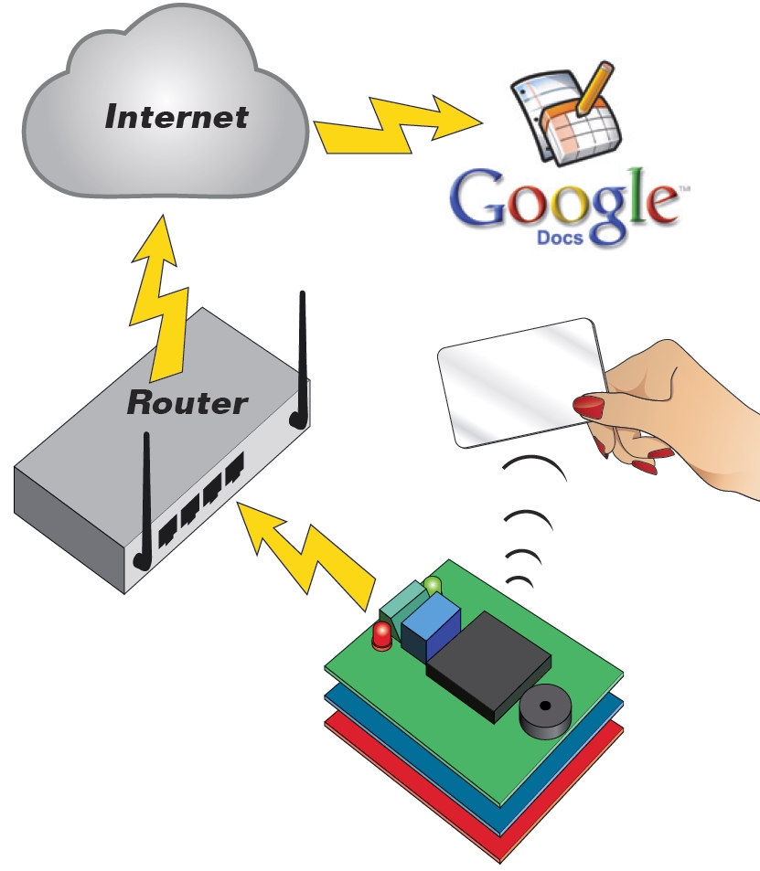
Our system may be facing a network and on the web to secure the cooperation of the Google Docs service. It only works if we add an Ethernet Shield.
Our online application proposes to use a Google Spreadsheet document (spreadsheet on Google Docs, anyway …) in which Arduino transcribe the codes read from valid cards. The only condition for accessing the service has to be registered, or have a Google account (eg Gmail), if you have not, open it: it is free and gives you the opportunity to have a mail box and many other free services offered by Google.
In practice, our system does not directly access to the spreadsheet, but sends the data using a form (form). We write a post to explain how to connect Arduino to Google Docs. All the results of a module is imported in the corresponding sheet, from which can be viewed by authorized users, or by anyone in possession of the link, if we remove the protection.
/* RFID shield Google
created 2011
by Andrea Fainozzi
This example code is in the public domain.
http://www.open-electronics.org
http://www.futurashop.it
http://blog.elettronicain.it/
*/
#include <EEPROM.h>
#include <NewSoftSerial.h>
#include <Ethernet.h>
#include <SPI.h>
#include <Client.h>
char formkey[] = "dDh11222222233333333344444444MQ"; //Chiave identificatrice del documento di google (SOSTITUIRE CON LA PROPRIA CHIAVE PRESA DIRETTAMENTE DALL'URL DI GOOGLE SPREADSHEET)
byte mac[] = { 0x90,0xA2,0xDA,0x00,0x55,0xA3}; //Mac addres della scheda ethernet dell'arduino (SOSTITUIRE CON IL MAC ADDRESS RIPORTATO SULLA SHIELD ETHERNET)
byte ip[] = { 192,168,0,99}; //IP da assegnare alla scheda ethernet dell'arduino (SOSTITUIRE CON UNO SUPPORTATO DALLA PROPRIA RETE)
byte subnet[] = { 255,255,255,0}; //Maschera di sottorete riferita alla propria connessione (SOSTITUIRE CON LA PROPRIA SUBNET MASK)
byte gateway[] = { 192,168,0,254}; //Gateway del proprio modem/router (SOSTITUIRE CON IL PROPRIO GATEWAY PREDEFINITO)
byte server[] = { 209,85,229,101 }; //IP del server di google spreadsheet
Client client(server, 80); //connettiamo il nostro arduino, come client al server di google spreadsheet
char buffer [33]; //vettore nel quale salvo temporaneamente vari caratteri che mi serviranno per leggere totalmente le tessere
char codice[13]; //stringa nella quale andremo a salvare il codice letto dalla tessera
#define PULSANTE 5 //pin relativo al pulsante da premere per entrare in modalità scrittura/cancellazione
#define DATA_PIN 7 //scegliere il pin che si vuole utilizzare in base alla scelta fatta con il jumper sulla scheda (7 |
#define RELE_PIN 9 //scegliere il pin che si vuole utilizzare in base alla scelta fatta con il jumper sulla scheda (9 | 10)
#define BUZZ_PIN 3 //scegliere il pin che si vuole utilizzare in base alla scelta fatta con il jumper sulla scheda (3 | 11)
#define GREEN_LED_PIN 8 //pin relativo al led verde
#define RED_LED_PIN 6 //pin relativo al led rosso
//scegliere cosa fare quando viene letta una scheda
#define RELE 1 //scegliere '1' per fare in modo che alla lettura di una scheda il relè venga attivato '0' per non fare nulla
#define BUZZER 1 //scegliere '1' per fare in modo che alla lettura di una scheda il buzzer emetta un suono '0' per non fare nulla
#define LED 1 //scegliere '1' per fare in modo che alla lettura di una scheda corretta venga acceso il led verde e per una scheda incorretta il led rosso '0' per non fare nulla
#define EEPROM_ON_OFF 1 //scegliere '1'(consigliato) per fare in modo che alla lettura di una tessera, il programma controlli che essa sia registrata per essere valida, '0' per fare in modo che una qualsiasi tessera con checksum valido sia considerata valida
#define DURATA_RELE 1000 //scegliere il tempo per il quale deve rimanere acceso il relè (se viene inserito '0' il relè funzionerà in modo bistabile)
boolean check; //variabile con la quale eseguo tutti i controlli all'interno dello sketch
int on_off=0; //variabile che utilizzo per controllare lo stato del led in modalità bistabile
NewSoftSerial mySerial(DATA_PIN,1); //inizializzo il pin sul quale leggere i dati trasmessi dall'ID-12
void setup() {
Serial.begin(9600);
Ethernet.begin(mac, ip , gateway , subnet);
if(DURATA_RELE>60000) //controllo che il tempo impostato per la durata di attivazione del relè sia inferiore a 1 minuto
while(1){ //in caso contrario stampo su seriale un messaggio di errore in un ciclo infinito
delay(2000);
Serial.print("Tempo relè non valido, troppo alto");
}
pinMode(PULSANTE,INPUT); //imposto il pin del pulsante in modalità input per verificare quando il pulsante viene premuto
digitalWrite(PULSANTE,HIGH); //e lo setto alto, in modo tale da attivare la resistenza di pull-up
if(RELE) //controllo se è stato scelto di attivare o meno il relè, nel primo caso, imposto il pin assegnatogli come output
pinMode(RELE_PIN,OUTPUT);
if(BUZZER) //controllo se è stato scelto di attivare o meno il buzzer, nel primo caso, imposto il pin assegnatogli come output
pinMode(BUZZ_PIN,OUTPUT);
if(LED){ //controllo se è stato scelto di attivare o meno i led, nel primo caso, imposto i pin assegnatogli come output
pinMode(GREEN_LED_PIN,OUTPUT);
pinMode(RED_LED_PIN,OUTPUT);
}
Serial.begin(9600); //Inizializzo la porta seriale sulla frequenza di 9600 baud
mySerial.begin(9600); //inizializzo la seriale sulla quale leggo i dati delle schede a 9600 baud
if(digitalRead(PULSANTE)==LOW) azzera(); //controllo che il il pulsante sia premuto in fase di accensione del dispositivo, in caso affermativo azzero tutta la memoria EEPROM
}
void loop () {
byte val; //variabile che utilizzo per leggere i valori dalla tessera appena passata
byte code[6]; //vettore nel quale salvo il codice letto completo
byte checksum; //variabile sulla quale calcolo e salvo il checksum
byte bytesread; //variabile che viene utilizzata per per contare quanti byte sono stati letti
byte tempbyte; //variabile che mi serve per memorizzare temporaneamente mezzo byte letto
unsigned long int tempo=0; //variabile che utilizzo per salvare il tempo attuale, per contare i millisecondi passati
boolean scrivere=false; //variabile che utilizzo per controllare se la tessera appena letta è da salvare o da controllare
boolean controllo=false; //variabile che utilizzo per controllare se la tessera appena letta è da cancellare oppure no
if(EEPROM_ON_OFF){
if(digitalRead(PULSANTE)==LOW){ //controllo se il pulsante è premuto
tempo=millis(); //se lo è salvo gli attuali millisecondi passati dall'avvio del dispositivo
while((digitalRead(PULSANTE)==LOW)&&(tempo+3000>millis())); //quindi mando in esecuzione un ciclo che non fa nulla
if(millis()>tempo+2999){ //controllo dopo la fine del ciclo se esso è stato in esecuzione per 3 secondi, confrontando il tempo iniziale + 3000 con il tempo attuale
if(LED)
digitalWrite(GREEN_LED_PIN,HIGH); //se così è, accendo il led verde
Serial.println("Modalità registrazione"); //e stampo sulla seriale che sono entrato in modalità registrazione
if(BUZZER){
analogWrite(BUZZ_PIN,50);
delay(50); //e faccio fare un suono di avviso al buzzer
digitalWrite(BUZZ_PIN,LOW);
}
scrivere=true; //e pongo a vero la variabile scrivere
}
if(digitalRead(PULSANTE)==LOW){ //se dopo ciò il pulsante è ancora premuto
while((digitalRead(PULSANTE)==LOW)&&(tempo+5000>millis())); //mando in esecuzione un altro ciclo nullo
if(millis()>tempo+4999){ //se esso è stato in esecuzione per 2 secondi significa che sono entrato in modalita eliminazione
Serial.println("Modalità eliminazione"); //quindi lo scrivo sulla seriale
if(LED){
digitalWrite(RED_LED_PIN,HIGH); //accendo il led rosso
digitalWrite(GREEN_LED_PIN,LOW); //spengo quello verde, precedentemente acceso
}
if(BUZZER){
analogWrite(BUZZ_PIN,50);
delay(50); //faccio fare un suono di avviso al buzzer
digitalWrite(BUZZ_PIN,LOW);
}
while(digitalRead(PULSANTE)==LOW); //mando in esecuzione un ciclo finchè il pulsante non viene rilasciato
controllo=true; //e pongo a vero la variabile controllo
}
}
}
}
//-------------------------------------------------------------------------------------inizio do-while------------------------------------------------------------------------------------------
do{ //inizio un ciclo che finirà solo quando verrà premuto nuovamente il pulsante
val = 0;
checksum = 0; //azzero le variabili precedentemente dichiarate
bytesread = 0;
tempbyte = 0;
if(mySerial.available() > 0) { //controllo se sulla mia seriale è presente qualche dato
if((val = mySerial.read()) == 2) { //se così è leggo da essa il valore
bytesread = 0; //e se è uguale a 2 (carattere di controllo) pongo a 0 la variabile bytesread
while (bytesread < 12) { //mando in esecuzione un ciclo per 12 volte, in modo da poter leggere tutti i 12 caratteri della tessera (5 byte del codice + 1 del cehcksum
if( mySerial.available() > 0) { //controllo se i dati sono disponibili ad essere letti
val = mySerial.read(); //quindi assegno a 'val' il valore dell'i-esimo carattere
if((val == 0x0D)||(val == 0x0A)||(val == 0x03)||(val == 0x02)) { //se leggo un carattere 'header' o un carattere di stop
break; // fermo la lettura
}
if ((val >= '0') && (val <= '9')) {
val -= '0';
} //traduco in esadecimale il carattere appena letto
else if ((val >= 'A') && (val <= 'F')) {
val = 10 + val - 'A';
}
//ogni 2 caratteri letti, aggiungo il byte così creato al vettore 'code'
if (bytesread & 1 == 1) { //se ho letto un solo carattere fin'ora
code[bytesread >> 1] = (val | (tempbyte << 4)); //assegno alla seconda parte del byte in posizione bytesread-esima il valore esadecimale del carattere letto
if (bytesread >> 1 != 5) { //se ho letto l'ultimo byte della scheda calcolo il checksum
checksum ^= code[bytesread >> 1]; //facendo la XOR sull'ultimo byte letto
};
} else {
tempbyte = val; //altrimenti assegno il valore letto alla variabile tempbyte
};
bytesread++; //mi preparo a leggere il prossimo byte
}
}
if (bytesread == 12) { //se ho letto tutti i 6 byte
(code[5]==checksum) ? check = true : check = false ; //controllo che il checksum sia corretto
if(EEPROM_ON_OFF){ //se è stato scelto di untilizzare la EEPROM
if(check){ //e il checksum è corretto, passo a controllare se devo salvare o cancellare
check=false; //rimetto a false la variabile check per successivi utilizzi
if(scrivere&&!controllo){ //controllo se devo scrivere
for(int i=0;i<1021;i+=5){ //in caso affermativo eseguo un ciclo che controlla tutta la EEPROM
if((EEPROM.read(i)==code[0])&&(EEPROM.read(i+1)==code[1])&&(EEPROM.read(i+2)==code[2])&&(EEPROM.read(i+3)==code[3])&&(EEPROM.read(i+4)==code[4])){
check=true; //se trovo il codice della tessera letta già salvato nella EEPROM metto a true la variabile 'check'
break; //ed esco dal ciclo
}
}
if(check){ //quindi controllo il valore della variabile check, se è vero, significa che la tessera è già stata registrata
Serial.print("Tessera già registrata!"); //quindi lo comunico su seriale
stampa_code(code);
if(LED)
digitalWrite(RED_LED_PIN,HIGH);
delay(50);
if(BUZZER)
analogWrite(BUZZ_PIN,50); //e mando un segnale di errore luminoso e/o sonoro in sempre in base al fatto che l'utente abbia specificato led e buzzer
delay(50);
if(BUZZER)
digitalWrite(BUZZ_PIN,LOW);
if(LED)
digitalWrite(RED_LED_PIN,LOW);
}
else{ //se la tessera non è stata trovata
check=false; //rimetto a false la variabile check per successivi utilizzi
for(int i=0;i<1021;i+=5){ //quindi eseguo un ciclo che controlla tutta la EEPROM in cerca di 5 byte successivi liberi
if((EEPROM.read(i)==0xff)&&(EEPROM.read(i+1)==0xff)&&(EEPROM.read(i+2)==0xff)&&(EEPROM.read(i+3)==0xff)&&(EEPROM.read(i+4)==0xff)){
for(int j=i;j<i+5;j++) //una volta trovati, partendo dal primo, fino al quinto, ci salvo il valore della tessera
EEPROM.write(j,code[j-i]); //eseguendo un ciclo 5 volte
check=true; //pongo a true la variabile check
break; //ed esco dal ciclo
}
}
if(check){ //se la variabile check è vera, significa che ho salvato con successo, quindi
Serial.print("Tessera Salvata"); //lo stampo su seriale
stampa_code(code);
if(BUZZER){
analogWrite(BUZZ_PIN,50);
delay(100);
digitalWrite(BUZZ_PIN,LOW);
}
if(LED){
for(int i=0;i<5;i++){
digitalWrite(GREEN_LED_PIN,HIGH); //e mando un segnale luminoso e/o sonoro in sempre in base al fatto che l'utente abbia specificato led e buzzer
delay(50);
digitalWrite(GREEN_LED_PIN,LOW);
delay(50);
}
digitalWrite(GREEN_LED_PIN,HIGH);
}
}
else{ //se la variabile check non è vera, significa che ho controllato tutta la memoria senza trovare 5 byte sequenziali liberi
Serial.println("Memoria piena"); //quindi spamo su seriale che la memoria è piena
for(int i=0;i<5;i++){
if(LED)
digitalWrite(RED_LED_PIN,HIGH);
if(BUZZER)
analogWrite(BUZZ_PIN,50);
delay(50); //e mando un segnale di errore luminoso e/o sonoro in sempre in base al fatto che l'utente abbia specificato led e buzzer
if(LED)
digitalWrite(RED_LED_PIN,LOW);
if(BUZZER)
digitalWrite(BUZZ_PIN,LOW);
delay(50);
}
}
}
}
else if(scrivere&&controllo){ //se non bisogna salvare, controllo se bisogna eliminare una tessera
int posizione=-1; //quindi inizializzo a -1 la variabile posizione, che mi servirà per salvare la posizione nella EEPROM della tessera
for(int i=0;i<1021;i+=5){ //ed eseguo un ciclo che controlla tutta la EEPROM per cercare il codice corrispondente
if((EEPROM.read(i)==code[0])&&(EEPROM.read(i+1)==code[1])&&(EEPROM.read(i+2)==code[2])&&(EEPROM.read(i+3)==code[3])&&(EEPROM.read(i+4)==code[4])){
posizione=i; //se viene trovato salvo la posizione del primo byte nella variabile posizione
break; //ed esco dal ciclo
}
}
if(posizione!=-1){ //quindi controllo che la variabile posizione sia diversa da -1 così da sapere se è stato trovato o meno il codice
for(int j=posizione;j<posizione+5;j++) //eseguo quindi un ciclo partendo dalla posizione 'posizione' nella EEPROM
EEPROM.write(j,0xff); //sovrascrivendo i 5 byte corrispondenti alla tessera, con il byte di default '0xff'
Serial.print("Scheda cancellata"); //una volta fatto ciò, stampo su seriale l'avvenuta cancellazione
stampa_code(code);
if(LED){
digitalWrite(GREEN_LED_PIN,HIGH);
digitalWrite(RED_LED_PIN,HIGH);
}
if(BUZZER)
analogWrite(BUZZ_PIN,50); //e mando un segnale luminoso e/o sonoro in sempre in base al fatto che l'utente abbia specificato led e buzzer
delay(250);
if(LED)
digitalWrite(GREEN_LED_PIN,LOW);
if(BUZZER)
digitalWrite(BUZZ_PIN,LOW);
}
else{ //se la variabile posizione vale -1 significa che non ha trovato in memoria la tessera letta
Serial.print("Impossibile cancellare la scheda, non è salvata"); //quindi lo comunico su seriale
stampa_code(code);
for(int x=0;x<10;x++){
if(LED)
digitalWrite(RED_LED_PIN,HIGH);
if(BUZZER)
analogWrite(BUZZ_PIN,50);
delay(25); //e mando un segnale di errore luminoso e/o sonoro in sempre in base al fatto che l'utente abbia specificato led e buzzer
if(LED)
digitalWrite(RED_LED_PIN,LOW);
if(BUZZER)
digitalWrite(BUZZ_PIN,LOW);
delay(25);
}
if(LED)
digitalWrite(RED_LED_PIN,HIGH);
}
}
check=true; //rimetto a vero il valore della variabile check siccome il checksum è corretto
}
else{ //se il checksum fosse incorretto
Serial.print("Checksum incorretto"); //lo comunico su seriale
for(int i=0;i<3;i++){
if(LED)
digitalWrite(RED_LED_PIN,HIGH);
if(BUZZER)
analogWrite(BUZZ_PIN,50);
delay(30); //e mando un segnale di errore luminoso e/o sonoro in sempre in base al fatto che l'utente abbia specificato led e buzzer
if(LED)
digitalWrite(RED_LED_PIN,LOW);
if(BUZZER)
digitalWrite(BUZZ_PIN,LOW);
}
if(LED)
digitalWrite(RED_LED_PIN,HIGH);
}
}
}
}
}
}
while((digitalRead(PULSANTE)==HIGH)&&(controllo||scrivere));
//-------------------------------------------------------------------------------------------fine do-while---------------------------------------------------------------------------------------
if(LED){
digitalWrite(GREEN_LED_PIN,LOW); //spengo gli eventuali led accesi per conoscere la modalità nella quale ero all'interno del ciclo
digitalWrite(RED_LED_PIN,LOW);
}
if (bytesread == 12) { //controllo di avere letto tutti i 6 byte della tessera
if(check&&EEPROM_ON_OFF){ //controllo che il checksum sia corretto e che è stato scelto di utilizzare la EEPROM
if(!scrivere){ //e controllo anche che non ci sia da salvare/scrivere una tessera
check=false; //rimetto a false la variabile check per successivi utilizzi
for(int i=0;i<1021;i+=5) //eseguo un ciclo che controlla tutta la EEPROM alla ricerca della tessera letta
if(EEPROM.read(i)==code[0]&&EEPROM.read(i+1)==code[1]&&EEPROM.read(i+2)==code[2]&&EEPROM.read(i+3)==code[3]&&EEPROM.read(i+4)==code[4]){
check=true; //se viene trovata metto a true la variabile check
break; //ed esco dal ciclo
}
if(check){ //quindi controllo il valore della variabile check
Serial.print("Tessera valida"); //se è vero, significa che la tessera è stata trovata e quindi è valida, e lo stampo su seriale
stampa_code(code);
stampa_codice(code,codice);
if(LED)
digitalWrite(GREEN_LED_PIN,HIGH);
if(BUZZER){
analogWrite(BUZZ_PIN,50);
delay(200);
digitalWrite(BUZZ_PIN,LOW); //quindi in base alla selezione dell'utente
} //mando un segnale luminoso e/o sonoro
if(RELE){ //in più accendo il relè
if(DURATA_RELE){ //secondo la modalità impostata dall'utente
digitalWrite(RELE_PIN,HIGH);
tempo=millis();
while(tempo+DURATA_RELE>millis());
digitalWrite(RELE_PIN,LOW);
}
else{
if(on_off){
digitalWrite(RELE_PIN,LOW);
on_off--;
}
else{
digitalWrite(RELE_PIN,HIGH);
on_off++;
}
}
}
google_send("entry.0.single",codice);
}
else{ //se al contrario il valore è falso
Serial.print("Tessera non valida!"); //significa che ho controllato tutta la memoria senza trovare la tessera, quindi lo comunico su seriale
stampa_code(code);
if(LED)
digitalWrite(RED_LED_PIN,HIGH);
if(BUZZER){
analogWrite(BUZZ_PIN,50);
delay(50);
digitalWrite(BUZZ_PIN,LOW); //e mando un segnale di errore luminoso e/o sonoro in sempre in base al fatto che l'utente abbia specificato led e buzzer
delay(50);
analogWrite(BUZZ_PIN,50);
delay(50);
digitalWrite(BUZZ_PIN,LOW);
}
}
}
if(LED){
delay(500);
digitalWrite(GREEN_LED_PIN,LOW); //spegno gli eventuali led rimasti accesi
digitalWrite(RED_LED_PIN,LOW);
}
}
else if(check&&!EEPROM_ON_OFF){
Serial.print("Tessera valida"); //se è vero, significa che la tessera è stata trovata e quindi è valida, e lo stampo su seriale
stampa_code(code);
stampa_codice(code,codice);
if(LED)
digitalWrite(GREEN_LED_PIN,HIGH);
if(BUZZER){
analogWrite(BUZZ_PIN,50);
delay(200);
digitalWrite(BUZZ_PIN,LOW); //quindi in base alla selezione dell'utente
} //mando un segnale luminoso e/o sonoro
if(RELE){ //in più accendo il relè
if(DURATA_RELE){ //secondo la modalità impostata dall'utente
digitalWrite(RELE_PIN,HIGH);
tempo=millis();
while(tempo+DURATA_RELE>millis());
digitalWrite(RELE_PIN,LOW);
}
else{
if(on_off){
digitalWrite(RELE_PIN,LOW);
on_off--;
}
else{
digitalWrite(RELE_PIN,HIGH);
on_off++;
}
}
}
google_send("entry.0.single",codice);
}
else if(!check){ //se il checksum fosse incorretto
Serial.print("Checksum incorretto"); //lo comunico su seriale
for(int i=0;i<3;i++){
if(LED)
digitalWrite(RED_LED_PIN,HIGH);
if(BUZZER)
analogWrite(BUZZ_PIN,50);
delay(30); //e mando un segnale di errore luminoso e/o sonoro in sempre in base al fatto che l'utente abbia specificato led e buzzer
if(LED)
digitalWrite(RED_LED_PIN,LOW);
if(BUZZER)
digitalWrite(BUZZ_PIN,LOW);
}
}
}
bytesread=0; //azzero la variabile bytesread per una prossima lettura
}
//--------------------------------------------------------------------------FUNZIONE PER AZZERARE LA MEMORIA EEPROM------------------------------------------------------------------------------
void azzera(){
if(LED){
digitalWrite(GREEN_LED_PIN,HIGH);
digitalWrite(RED_LED_PIN,HIGH);
}
for(int i=0;i<1023;i++)
EEPROM.write(i,0xff);
Serial.println("Memoria Azzerata!");
if(BUZZER)
analogWrite(BUZZ_PIN,50);
for(int i=0;i<5;i++)
if(LED){
digitalWrite(GREEN_LED_PIN,HIGH);
delay(100);
digitalWrite(GREEN_LED_PIN,LOW);
digitalWrite(RED_LED_PIN,HIGH);
delay(100);
digitalWrite(RED_LED_PIN,LOW);
}
if(BUZZER)
digitalWrite(BUZZ_PIN,LOW);
}
//--------------------------------------------------------------FUNZIONE PER STAMPARE IL CODICE DELLA TESSERA LETTA SU SERIALE-------------------------------------------------------------------
void stampa_code(byte * code){
Serial.print(": <");
for (int i=0; i<5; i++) {
if (code[i] < 16) Serial.print("0");
Serial.print(code[i], HEX);
if(i!=4)
Serial.print(" ");
}
Serial.println(">");
}
//------------------------------------------------------------FUNZIONE PER INVIARE A GOOGLE SPREADSHEET IL VALORE DELLA TESSERA LETTA------------------------------------------------------------
void google_send(char *entry,char *val){
char *submit = "&submit=Submit";
if (client.connect()) {
client.print("POST /formResponse?formkey=");
client.print(formkey);
client.println("&ifq HTTP/1.1");
client.println("Host: spreadsheets.google.com");
client.println("Content-Type: application/x-www-form-urlencoded");
client.print("Content-Length: ");
client.println(strlen(entry)+1+strlen(val)+strlen(submit),DEC);
client.println();
client.print(entry);
client.print("=");
client.print(val);
client.print(submit);
client.println();
}
delay(1000);
client.stop();
}
//-----------------------------------------------------------FUNZIONE PER CONVERTIRE DA BYTE A CARATTERE IL VALORE DELLA TESSERA LETTA-----------------------------------------------------------
void stampa_codice(byte * code,char * codice){
char tmp[3];
codice[0]='\0';
for(int i=0;i<5;i++){
sprintf(tmp, "%02X", code[i]);
strncat(codice,tmp,2);
}
}
[Thanks to Andrea Fainozzi]
Merged in my Arduino blog
I decided that it was too much hassle maintaining 2 blogs (one of which was rarely read and which I didn’t often add stuff to). My previous blog about the Arduino microprocessor, printed circuit board design, and robotics has now been merged into this one.
The way the merging of blogs on WordPress.com works, all the posts retained their old dates, so they do not appear as new posts here. I’ll try to point back to the old posts as I add new stuff to the categories, but if you want to scroll through all the posts, you can do so by visiting the new categories (I think that all the posts in that blog had categories, as it was a much more organized blog than this one):
- Data acquisition
- Digital music
- Makers’ Factory
- Metacomments (about the blog)
- Printed Circuit Boards
- Robotics
- Software
I’ll also try going through my posts on this blog, trying to find ones that belong in the new categories. I may even try adding some categories for tags that have gotten used a lot. This cataloging will take a while, as it is fairly low on my priority list.
Tagged: Arduino, blog


